

ETS Lumagen 26C User Manual
Ultraviolet radiation. Follow instructions. Avoid overexposure. As with
natural sunlight, overexposure can cause eye and skin injury and
allergic reactions. Repeated exposure may cause premature aging of the skin and skin cancer.
WEAR PROTECTIVE EYEWEAR; FAILURE TO MAY RESULT IN SEVERE BURNS OR
LONGTERM INJURY TO THE EYES. Medications or cosmetics may increase your sensitivity
to the ultraviolet radiation. Consult physician before using sunlamp if you are using medications
or have a history of skin problems or believe yourself especially sensitive to sunlight. If you do
not tan in the sun, you are unlikely to tan from the use of this product. Children, the elderly, or
fair skinned people who always burn easily and either never tan or tan minimally should not use
this equipment.
To use, lie down under canopy and pull down as far as adjustment will allow. Do not use without
clear plastic panels in place. Untanned persons should not tan on consecutive days during their
first week of tanning. Never tan more than once a day. Tanning normally appears after the first
few sessions and maximizes after approximately four weeks. Tan once or twice per week there-
after to maintain appearance. Persons already having a base tan may begin at advanced levels
corresponding to the extent of their base tan.
Skin Type:
I Sensitive Skin (Burns easily and severely and does not tan.)
II Light Skin (Burns easily and severely and tans minimally.)
III Normal Skin (Burns moderately and tans average.)
IV Dark Skin (Burns minimally, tans easily and above average.)
New lamps emit approximately 10% more ultraviolet radiation during the first 50 hours of
operation. Recommended tanning times should therefore be reduced by approximately 10%
during that period.
W
ARNING: •
Read all instructions before using this sunlamp product.All persons in the room should wear
protective eyewear when lamps are on. Required eyewear: Ultra SunGlobes®, special-eyez, or other dark-
tinted eyewear that meet 21 CFR 1040.20 guidelines. Other eyewear may not provide adequate protection.
The following lamps have been certified for use in the Lumagen™ 26C:
Velocity® Wolff® Model VEL 71-T12-100W
Lumalite C™ Wolff® P/N 27743-01
DermaSun™ Wolff® P/N 27744-01
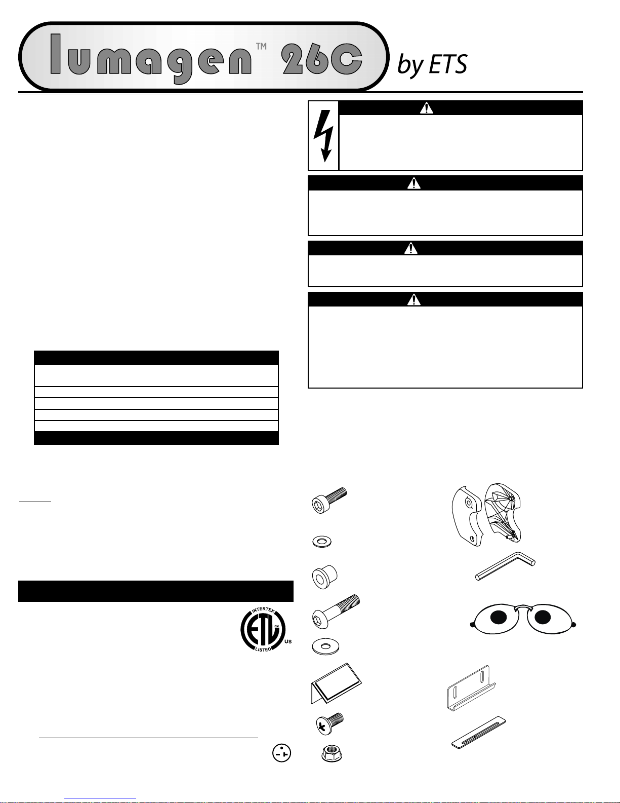
THIS EQUIPMENT MUST BE EARTH GROUNDED.
This product is in conformity with performance standards for sun lamp
products under 21 CFR PART 1040.20 and ANSI/UL Standard 482.
WARNING
Wear protective eyewear.
Failure to may result in severe burns or longterm injury to the eyes.
DANGER
Shock hazard.
Disconnect power before servicing or removing any protec-
tive covers.
Do not operate this device near water or while you are wet.
DANGER
Some medications may increase your sensitivity to ultraviolet light. It
is recommended that you consult a physician before using this
sunbed if taking any medication or if you suspect that your skin might
be especially sensitive to sunlight.
CAUTION
Use of a voltage source above 230V AC may prevent proper operation
of the sunbed and could cause damage and void the warranty.
Air from the room is used to cool the sunbed. Maximum ambient room
temperature should be 80°F. Place your sunbed no closer than 6” from
any wall. Make sure nothing obstructs the airflow into the sunbed’s
endcaps or out of the fan openings. A poorly ventilated room may
cause the unit to become hot and cause discomfort to the user.
Electrical Requirements
Your sunbed operates from a 220V AC source. The 26C requires a NEMA
6-20R electrical outlet (below) on a dedicated circuit capable of pro-
viding 20 Amp service, installed in the room in which you will use the
unit. W
e recommend installation by a professional electrician. The out-
let must be earth grounded.
20 AMP NEMA #6-20R
RECEPTACLE
27771-01A - Page 1
DANGER
Unpacking and Inspection
The canopy box contains the canopy and a pair of gas springs. The
bench box contains the bench, assembly hardware, stand legs and skirt.
Inspect the items and make sure they are free from any visible damage.
Report the extent of any damage to the transportation company.
Allen-head Bolt 5/16” x 1”
Quantity 2
5/16” Metal Washer
Quantity 2
Bushing
Quantity 2
Allen-head Bolt 5/16” x 1 1/2”
Quantity 2
Nylon Washer
Quantity 2
Hinge Brackets
(1) left, (1) right
Hex (Allen) Wrench
Quantity 1
Safety Goggles
Quantity 1
Hardware Inventory (These items and a small pillow)
88465
DISCONNECT POWER CORD BEFORE ATTEMPTING TO CLEAN, RELAMP,
OR ENGAGE IN THE MAINTENANCE OF THIS PRODUCT.
RECOMMENDED EXPOSURE TIMES IN MINUTES
Level 1/Week 1
Level 2Level 3Level 4Level 5
Skin Type: 1st-3rd Sessions
I Sensitive NOT RECOMMENDED FOR TANNING
II Light 4 8 12 16 20
III Normal 6 10 15 20 20
IV Dark 8 12 16 20 20
MAXIMUM EXPOSURE TIME IS 20 MINUTES
Skirt Top Bracket
Quantity 3
Skirt Reinforcing Plate
Quantity 2
Screw #10-32 x 1/2”
Quantity 4
Nut #10-32 Locking
Quantity 4
Skirt Mounting Bracket
Quantity 2
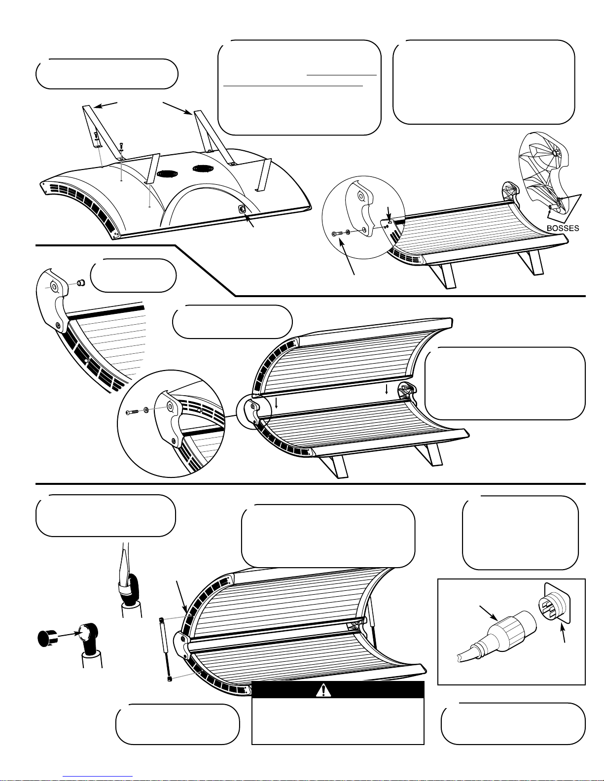
Lay the bench upside down on the
floor. Locate the two stand legs.
1
Remove the six 5/16” x 1” bolts and
5/16” washers installed in the bench.
Attach the stand legs, with the tw
o small
skirt mounting holes toward the front
, by
installing the center bolt first. You may
have to gently push the sides of the legs
in to align holes. Tighten with the Allen
wrench.
2
SKIRT MOUNTING HOLES
Page 2 - 27771-01A
Assembly Procedures
(ELECTRICAL CONNECTOR
INDICATES BACK OF BENCH)
SHORT BOLT
Turn bench over. Install hinge brackets to
ends of bench such that the short boss
engages the stud above the bolt hole, and the
long boss engages the hole below the bolt
hole. Secure using 5/16” x 1” Allen-head
bolts and 5/16” metal washers. Tighten bolt
snug, then an additional half turn.
3
Place the bushings
into hinge brackets.
4
Lift the canopy and hold it
between the hinge brackets.
5
Insert 5/16” x 1 1/2” bolts with nylon
washers into both hinge brackets.
Tighten bolts into the endcap threaded
inserts until snug, then an additional
half turn. Do not overtighten to avoid
damaging threaded inserts.
6
PIVOT STUD
CAUTION
Failure to engage locking clips may
result in the ball joints working loose,
allowing the canopy to fall, whi ch may
result in damage to the unit and injury.
Type 1
Pry back the
locking clip
with a flat
screwdriver.
The gas springs have a locking
mechanism. Follow the directions
below for the type you received.
7
With a helper holding the canopy open,
align ends of gas spring ball joints with
pivot studs and push into place. Be sure
rod end is down as shown. DO NOT lower
canopy until both gas springs are engaged!
8
Lift and lower canopy a few
times to lubricate gas springs
for optimum performance.
9
Connect the canopy to
bench power cord to the
bench receptacle. Align the
terminals and firmly push
on until seated then tighten
the threaded locking ring.
10
Plug the three-prong 220V AC
power cord into a dedicated outlet
(see Electrical Requirements).
11
STUD
Type 2
Remove locking
clip to install or
remove gas spring.
THREADED
LOCKING RING
RECEPTACLE
ON BENCH
CANOPY TO BENCH
POWER CORD
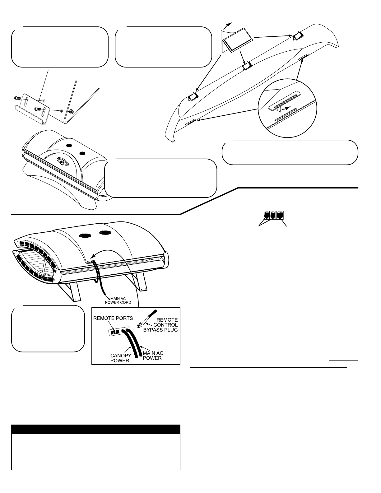
The unit is shipped with a
Remote Control Bypass
Plug installed. Your sunbed
will not operate without
either the bypass plug or a
remote system connected.
16
27771-01A - Page 3
On the front of each leg are two holes
for skirt mounting brackets. Locate
the two brackets and attach them as
shown with two #10-32 x 1/2” screws
and two #10-32 locking nuts each.
12
Remote Connections
Your sunbed incorporates advanced circuitry allowing it to connect and
communicate with most remote control systems. If a remote system is
to be used, first determine whether the remote system is a T-Max®
Manager Pro System or a standard remote system operating with a control relay. Follow the appropriate instructions for your system type.
The remote connection is not designed to supply or accept high
voltage, nor can it provide power to an external timer. The
sunbed’s remote interface circuitry operates on 5 volts, attempting
to connect it to any higher voltages will damage the sunbed as
well as void your warranty.
CAUTION
REMOTE PORTS
WIRED
REMOTE
PORTS (RJ-22)
WIRELESS
REMOTE
PORT (RJ-11)
T-Max® Manager Pro
The T-Max® Manager Pro offers the ultimate in sunbed control, while
allowing the tanner easy straightforward operation. Your sunbed is
configured to directly connect to this system, including the new wireless remote system. The circuitry inside your sunbed eliminates the
need for the T-Max® 1A or 3A when connecting to the T-Max®
Manager Pro. Your sunbed supports the auto addressing feature of the
Manager Pro and the following parameters: 5, 6, 7, 8, 9, 10, 15 and
23. See your T-Max® manual for descriptions of these parameters and
how they function.
Special Note on T-Max®
The Lumagn™ 26C requires the latest software in your T-Max Manager
Pro to properly control the sunbed. To check for this, when applying
power to the Manager Pro a 3-digit version number will appear on the
left-hand side of the screen. This must be 415 or higher. T
his sunbed
will only work with a Manager Pro, not an older Manager or 3A.
T-Max® Wireless Remote System
The T-Max® AP-900 eliminates wires in your salon, allowing easy
setup without hiring an electrician to run wires. It also protects your
investment from damage by isolating each unit from one another. Your
sunbed arrives “wireless ready”, which means it connects directly to
the T-Max® wireless system. Older tanning beds, and T-Max® managers, also utilize this system but require a T-Max “Power Injector” (PI)
to provide the needed power to the wireless unit.
Remote System Hook-up Scenarios
Follow the diagrams on the next page to see the many different scenarios for hooking up your salon. If you need further assistance, call TMax® directly at (417) 338-5101.
Slip the slots in the bottom of the skirt onto
the skirt mounting brackets. Peel the backing
from the Velcro® pad on each top bracket
and press the top brackets to the bench
cover. Press firmly so the pads stick.
15
Peel the backing from the doublesided tape on each skirt top bracket
and attach them to the skirt as shown.
Make sure the corner lines up with
the top edge of the skirt as shown.
13
Peel the backing from the double-sided tape on each
skirt reinforcing plate and press them onto the skirt so
the slot in the plate lines up with the slot in the skirt.
14
 Loading...