

ETS Ingenico iSC250, iSCTouch250 Installation Manual
Innovative Payment Processing Solutions for Businesses
January 2016
iSC250 Installation and
Configuration Guide
Version 1.0

©2016 ETS Corporation | iSC250 Installation and Configuration Guide
2
This information is CONFIDENTIAL and must be used exclusively for the operation of ETS software, hardware, or services. It
may not be duplicated, published, or disclosed without the express permission of ETS.
Contents
1. Terminal Installation ............................................................................................................................. 3
2. Terminal Configuration ......................................................................................................................... 8
2.1 Configuring the iSC250 for Ethernet Mode (TCP/IP Enabled Terminals with Included Ethernet
Cable) ........................................................................................................................................................ 8
2.2 Configuring the iSC250 for USB-Serial Mode (USB Enabled Terminals with Included USB Cable) ... 17

©2016 ETS Corporation | iSC250 Installation and Configuration Guide
3
This information is CONFIDENTIAL and must be used exclusively for the operation of ETS software, hardware, or services. It
may not be duplicated, published, or disclosed without the express permission of ETS.
1. Terminal Installation
Introduction
Ingenico’s iSC250 and iSCTouch250 secure electronic payment devices consist of the following:
ADA-friendly, illuminated keypad
Dual-head, bi-directional magnetic stripe reader
3.5” color touch Wide QVGA screen supporting full motion video, with finger and stylus touch
input
Signature capture
Integrated contactless card/NFC reader
EMV Smart card reader
Device Installation
The installation procedure includes:
Selecting the device location
Connecting the stylus
Connecting the device
Connecting the power supply
Securing the device
Each step is described in the sections below:
Box Contents
Note: Carefully inspect the shipping carton and its contents for shipping damage. If the device is
damaged, please contact ETS at 800 834 7790, select option 2.
1. Remove the contents from the box. You should have:

©2016 ETS Corporation | iSC250 Installation and Configuration Guide
4
This information is CONFIDENTIAL and must be used exclusively for the operation of ETS software, hardware, or services. It
may not be duplicated, published, or disclosed without the express permission of ETS.
A. iSC250
B. Stylus
C. Cable (specific to
your connectivity
requirements)
2. Remove the protective film from the graphical display screen.
3. Save the carton and packing material for repackaging or moving the device in the future.
Selecting the Device Location
The iSC250 may be mounted on a flat surface, wall, or customer stand (recommended). Ingenico
recommends physically securing the device to avoid theft. Power may be provided from a host Point of
Sale system or from an Ingenico power supply. If using an Ingenico power supply, the device must be
placed close to an easily-accessible power outlet.
Note 1: Do not place the iSC250 on a PC monitor, adjacent to an electronically active security tag,
deactivation system, or near other sources of magnetic fields.
Note 2: The iSC250 must be at least 12 inches away from an electronically active type of security tag
deactivation pad. There are two types of security tag deactivation systems:
An electronically active system sends out a powerful and potentially disruptive signal to
deactivate the security tag. If the iSC250 is placed too close to the system’s pad, or placed
above the pad, malfunction may occur.
A passive system is a permanent magnet type that does not send out a signal. This type does
not affect the iSC250
©2016 ETS Corporation | iSC250 Installation and Configuration Guide
5
This information is CONFIDENTIAL and must be used exclusively for the operation of ETS software, hardware, or services. It
may not be duplicated, published, or disclosed without the express permission of ETS.
Connecting the Stylus
1. With the stylus cable’s locking tab towards the bottom, insert the stylus connector into the
iSC250 stylus port on the back of the iSC250. It will click, indicating that it is locked home when
fully inserted.
Figure 1: Inserting the stylus connector into the stylus port
2. Place the stylus into the cradle on the left edge of the iSC250 device, or insert it upright into the
hole in the cradle. There is a plastic plug in this hole that needs to be removed.
Connecting the Device
Note: Do not connect power to the iSC250 device until instructed to do so.
1. Place the iSC250 device in front of you with the bottom of the unit facing up. Be careful not to
place the device on a surface where the device can be scratched or damaged.
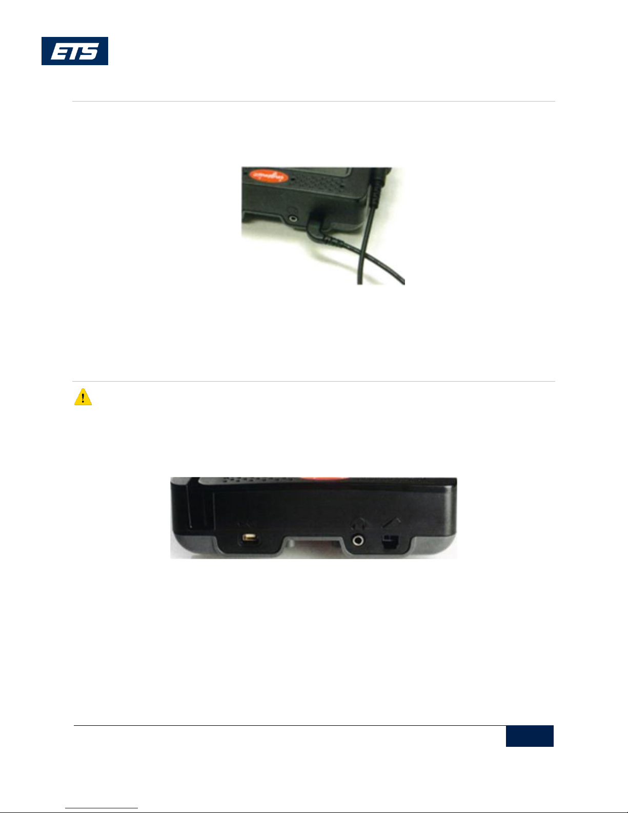
2. Connect a peripheral device to the appropriate available port on the rear of the device.
Figure 2: iSC250 Peripheral Ports
©2016 ETS Corporation | iSC250 Installation and Configuration Guide
6
This information is CONFIDENTIAL and must be used exclusively for the operation of ETS software, hardware, or services. It
may not be duplicated, published, or disclosed without the express permission of ETS.
Icon
Port
Description
USB
USB 2.0 Host high speed, 5V, 500mA max. Supports peripheral USB
devices.
Audio Out
3.5 mm stereo audio jack. Use to connect exteral speakers or
headphones.
Stylus
Use to connect the stylus.
Icon
Port
Description
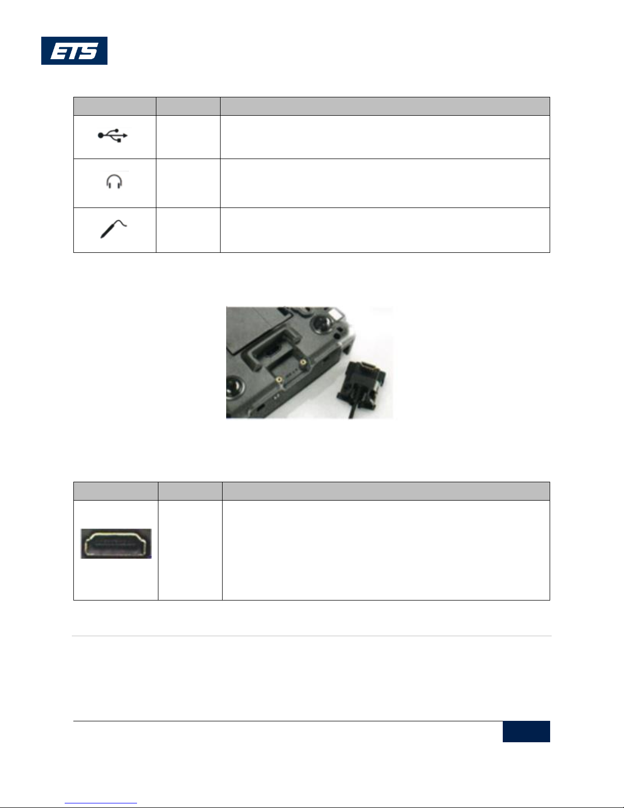
Multipoint
port
Use to connect Ethernet or USB. Use this port to connect host
devices (POS or PC) directly. The iSC250 receives power through this
connection.
For this device to be USB-IF compliant, only use the approved USB
cable from Ingenico.
Table 1: iSC250 Peripheral Ports
3. Connect the interface cable (Ethernet or USB) into the iSC250 HOST multipoint port. Connect
the other end to the POS or PC, as appropriate (see Table 2).
Figure 3: iSC250 Multipoint Port
Table 2: iSC250 Multipoint Port
Cables
Note: Only iSC250 cables supplied by Ingenico may be used (if the cables are missing or damaged,
please contact ETS at 800 834 7790, select option 2).
©2016 ETS Corporation | iSC250 Installation and Configuration Guide
7
This information is CONFIDENTIAL and must be used exclusively for the operation of ETS software, hardware, or services. It
may not be duplicated, published, or disclosed without the express permission of ETS.
Connecting a Power Supply
A separate Ingenico DC power supply (192011597) is required when connecting the iSC250 device, USB
(5V), and Ethernet. When the device is powered from a POS, power may be provided via a powered USB
(12V).
Note: Connect the cable to the Multipoint port before connecting the device to power. Only use
the power supply provided by Ingenico.
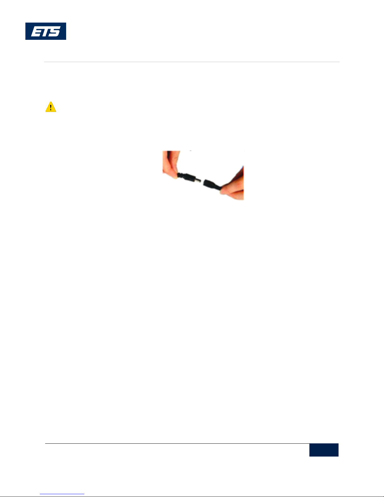
1. Plug the power supply connector into the jack on the multipoint cable.
Figure 4: Connecting a Power Supply
2. Plug the power supply into a power outlet.
3. The iSC250 initializes when power is applied.
 Loading...