

ETS HSM11-SMA1 Installation

HSM11-SMA1 Speaker / Microphone Kit Instructions
The HSM11-SMA1 kit is an indoor / outdoor two way public address, audio surveillance system that is designed to
interface with DVRs and I/P cameras. The HSM11 speaker / pre-amplified microphone is designed to mount on hard flat
surfaces such as concrete or wood. The SMA1 is typically located near the DVR or I/P camera. Note-input and output
signals on the SMA1 are “line level” only. The HSM11-SMA1 is for use in half duplex audio systems only. Audio whi ne or
“feedback” will be result if both speaker and microphone are active at the same time.
HSM11 Microphone / Speaker Placement.
Locate the HSM11 speaker / microphone near the area of interest in the space to be monitored. If a large area is to be
monitored, locate the HSM11 in the middle of the space if possible. Avoid mounting the speaker / microphone near air
conditioning vents, light fixtures or electrical equipment. The HSM11 should be placed as close to the subject(s) a s
possible. 5 to 10 feet is ideal. The HSM11 is still useable in the range of 15-25 feet in public address applications but is
dependent on the level of background noise in the area. Experimentation in the environment will determine what distances
work best.
Audio Signal Cable Runs
Recommended cable is: 2 each 22 gauge, stranded, two conductor shielded cables (one for the microphone and the
other for the speaker) between the SMA1 amplifier / interface and the HSM11 microphone / speaker. Keep the cable run
distances under 1,000 feet and away from AC power sources, light fixtures and electrical equipment. Make connections
as shown in Figure 1.
HSM11 Mounting
The HSM11 is designed to be mounted on ceilings or walls and features swivel adjustments for directional aiming. Make
wire connections inside the weather tight box on the back of the HSM11and screw the lid down. Mount the speaker in a
fashion that does not allow water to directly flow (from driving rain etc.) inside the junction box. Leave the factory set
jumper on the MSI circuit board in the 5 watt position and the power switch setting on the horn at 8 watts. Sound levels for
the speaker and microphone are user adjustable on the SMA1 interface box.
SMA1 location and power:
The SMA1 interface box is designed to be located next to a DVR or I/P camera. The SMA1requires a 120VAC power
source within 3 feet of its location. If this is not possible in your application, you can splice in up to 100 feet of 18 awg, 2
conductor cable to extend the distance between the AC power source and the SMA1.
SMA1 70V / 8 Ohm direct switch:
When using the SMA1 with a HSM11 or CSM8 speaker / microphone, make sure this switch is in the 70V position.
DVR or I/P camera connections:
Connect the “audio out” of the SMA1 to the “audio in” of the DVR or I/P camera. Connect the “audio in” of the SMA1 to the
“audio out” of the DVR or I/P camera. Note-input and output signals on the SMA1 are “line level” only. If the DVR or I/P
camera uses screw terminals for audio conn ections, simply cut off the ends of the supplied RCA patch cables, strip the
wires back and connect the wires to the I/P camera terminal blocks. The center conductor of a cut patch cable is + and
the shield is -.
Adjusting the SMA1 Levels:
Set both level controls to 1/8 clockwise from full counter clockwise on the SMA1 before powering the system up. Adjust
the controls + or – to the desired levels for both speaker and microphone. If the microphone sound at the DVR or head
end is distorted, rotate the control towards the – mark (counter- clockwise). Adjust the volume of the speaker to the
desired level. If the speaker volume is too high, amplifier oscillations may result. Turn the level control down if you
experience this. Note-leave the MSI-1 jumper in the 5W position.
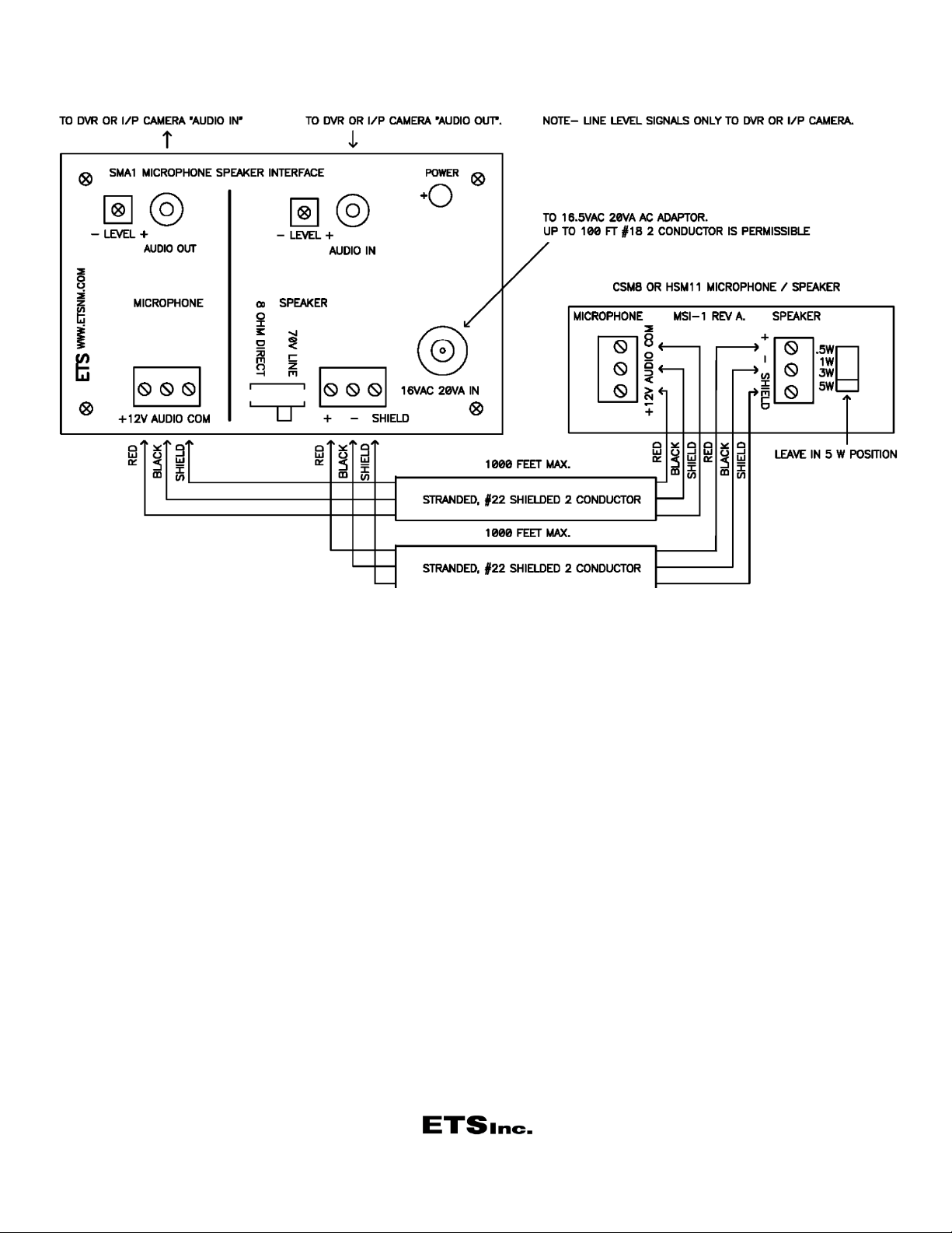
Figure 1.
Caution
It may be against the law to install this microphone kit in certain environments. It may also be against the law to record
conversations of the person(s) being monitored without their knowledge. It is the responsibility of the installation compan y
and end-user to determine if the application of this product is legal. These laws vary from state to state. If you are not
informed on these matters, consult a qualified attorney or contact the appropriate state agency. A sticker is provided with
this kit for the applications where notification must be posted.
Warranty
All ETS products carry a one year parts and labor warranty. This warranty does not cover damages as a result of misuse,
improper handling of the unit or exposure to extreme temperatures or moisture. At its discretion, ETS reserves the right to
repair or replace this unit under the conditions of the warranty. If you experience problems with your equipment call ETS
at: 505-888-3923 to obtain a return authorization number. Equipment requiring repair beyond the warranty period or u nits
that have been damaged or are not covered under the warranty can be repaired by ETS for a minimal cost under most
conditions.
Made in the USA
by
 Loading...