

Page 1
VECTOR 300
Service Manual
1
Page 2

Contents
1. INFORMATION
1-1 Safety
1-2 Notes
1-3 Engine Specifications
1-4 Serial Number
1-5 Torque Values
1-6 Special Tools
2. MAINTENANCE
2-1 Maintenance Data
2-2 Maintenance Schedule
2-3 Fuel Tube
2-4 Throttle Operation
2-5 Throttle Cable Adjustment
2-6 Air Cleaner
2-7 Spark Plug
2-8 Idle Speed
2-9 Drive Chain
2-10 Brake System
2-11 Wheels And Tires
2-12 Steering Shaft Holder Bushing
2-13 Toe-In
3. ENGINE REMOVE AND INSTALLATION
3-1 General Information
3-2 Engine Removal
3-3 Engine Installation
4. LUBRICATION SYSTEM
4-1 Mechanism Diagram
4-2 Precautions In Operation
4-3 Troubleshooting
4-4 Engine Oil
4-5 Engine Oil Strainer Clean
4-6 Oil Pump
4-7 Gear Oil
5. FUEL SYSTEM
5-1 Mechanism Diagram
5-2 Precautions In Operation
5-3 Trouble Diagnosis
5-4 Carburetor Remove / Install
5-5 Air Cut-Off Valve
5-6 Throttle Valve
5-7 Float Chamber
5-8 Adjustment Of Idle Speed
5-9 Fuel Tank
5-10 Air Cleaner
Page 3

6. CYLINDER HEAD/VALVE
6-1 Mechanism Diagram
6-2 Precautions In Operation
6-3 Troubleshooting
6-4 Cylinder Head Removal
6-5 Cylinder Head Inspection
6-6 Valve Stem Replacement
6-7 Valve Seat Inspection And Service
6-8 Cylinder Head Reassembly
6-9 Cylinder Head Installation
6-10 Valve Clearance Adjustment
7. CYLINDER/PISTON
7-1 Mechanism Diagram
7-2 Precautions In Operation
7-3 Trouble Diagnosis
7-4 Cylinder And Piston Removal
7-5 Piston Ring Installation
7-6 Piston Installation
7-7 Cylinder Installation
8. V-BELT DRIVING SYSTEM
8-1 Mechanism Diagram
8-2 Maintenance Description
8-3 Trouble Diagnosis
8-4 Left Crankcase Cover
8-5 Drive Belt
8-6 Drive Face
8-7 Clutch Outer/Driven Pulley
9. FINAL DRIVING MECHANISM
9-1 Mechanism Diagram - Transmission Cover
9-2 Precautions In Operation
9-3 Trouble Diagnosis
9-4 Disassembly Of Transmission
9-5 Inspection Of Mission Mechanism
9-6 Bearing Replacement
9-7 Re-assembly Of Final Driving Mechanism
10. ALTERNATOR/STARTING CLUTCH
10-1 Mechanism Diagram
10-2 Precautions In Operation
10-3 Right Crankcase Cover Removal
10-4 A.C.G. Set Removal
10-5 Right Cover Bearing
10-6 Flywheel Removal
10-7 Starting Clutch
10-8 Flywheel Installation
10-9 A.C.G. Set Installation
10-10 Right Crankcase Cover Installation
Page 4

11. CRANKCASE / CRANK
11-1 Mechanism Diagram
11-2 General Information
11-3 Trouble Diagnosis
11-4 Disassembly Of Crankcase
11-5 Crankshaft Inspection
11-6 Assembly Of Crankcase
12. COOLING SYSTEM
12-1 Mechanism Diagram
12-2 General Information
12-3 Trouble Diagnosis
12-4 Trouble Diagnosis For Cooling System
12-5 System Test
12-6 Radiator
12-7 Water Pump
12-8 Thermostat
13. STEERING AND SUSPENSION
13-1 Parts Drawing
13-2 Troubleshooting
13-3 Handlebar
13-4 Throttle Housing
13-5 Steering System
14. FRONT WHEEL AND BRAKE SYSTEM
14-1 Parts Drawing
14-2 Troubleshooting
14-3 Front Wheels
14-4 Hydraulic Brake
14-5 Suspension Adjustment
15. REAR WHEEL AND BRAKE SYSTEM
15-1 Parts Drawing
15-2 Troubleshooting
15-3 Remove Rear Wheel And Rear Brake
15-4 Swingarm & Rear Axle Holder
15-5 Suspension Adjustment
16. FENDERS AND EXHAUST PIPE
16-1 Fenders Drawing
16-2 Rear Fenders Removal
16-3 Front Fender Removal
16-4 Exhaust Pipe Removal
Page 5

17. ELECTRICAL SYSTEM
17-1 Troubleshooting
17-2 Ignition Coil
17-3 Ignition Timing
17-4 Battery Information
17-5 Electric Starter
17-6 Light Bulbs Replacement
17-7 Instrument Pane
17-8 Wiring Diagram
18.TROUBLESHOOTING
18-1 Engine Can Not Work
18-2 Poor Performance At Low And Idle Speeds
18-3 Poor Performance At High Speed
18-4 Loss Power
18-5 Poor Handling
Page 6

1. INFORMATION
1-1 Safety
1-2 Notes
1-3 EngineSpecifications
1-4 Serial Number
1-5 Torque Values
1-6 Special Tools
1-1 Safety
GASOLINE
Gasoline is extremely flammable and is explosive under certain conditio n.
Do not smoke or allow sparks or flames in your work area.
● CARBON MONOXIDE
Never run the engine in a closed area. The exhaust contains poisonous carbon
monoxide gas that may cause loss of consciousness and lead to death.
● BATTERY ELECTROLYTE
The battery electrolyte contains sulfuric acid. Protect your eyes, skin and
clothing. If you contact it, flush thoroughly with water and call a doctor if electrolyte
gets in your eyes.
● HOT PARTS
Engine and exhaust pipe become very hot and remain hot for one hour after the
engine is run. Wear insulated gloves before handling these parts.
● USED ENGINE/GEAR OIL
Used engine oil and gear oil may cause skin disease if repeatedly contact with
the skin for long periods.
Keep out of reach of children.
1-2 Notes
All information, illustrations, directions and specifications included in this publication are base on the latest
product information available at the time of approval for printing.
JI-EE Dynamic Technology Industry Co., Ltd. reserves the right to make changes at any time without notice and
without incurring any obligation whatever.
No part of this publication may be reproduced without written permission.
6
Page 7

1-3 EngineSpecifications
Type
Displacement 287.2c.c.
Bore and Stroke 75 mm x 65 mm
Compression 10.0:1
Maximum Hp 20ps / 6500
Maximum Torque (Nm/rpm) 24.6 Nm / 5000
Carburetor
Ignition DC-CDI
Starting Electric
Lubrication Auto oil injection
Transmission Automatic (C.V.T. V-belt + Reverse)
CHASSIS
Overall Length
Overall Width
Overall Height
Wheel base
Ground Clearance
Dry Weight
Fuel Tank Capacity
SUSPENSION
Front
Rear
BRAKES
Front
Rear
TIRES
Front
Rear
PRESSURE【 psi ( kgf/cm2)】
Front
Rear
COLORING
Specifications subject to change without notice.
4 Stroke,Sin gle Cylinder, Water cooled
1815mm
1062mm
1130mm
1193mm
150mm
Double A-Arm & Adjustable
Swing Arm & Adjustable Shock
Front Hydraulic Disc*2
Rear Hydraulic Disc*1
21x7-10
22x10-10
12(0.8)
12(0.8)
225Kg
12L
7
Page 8
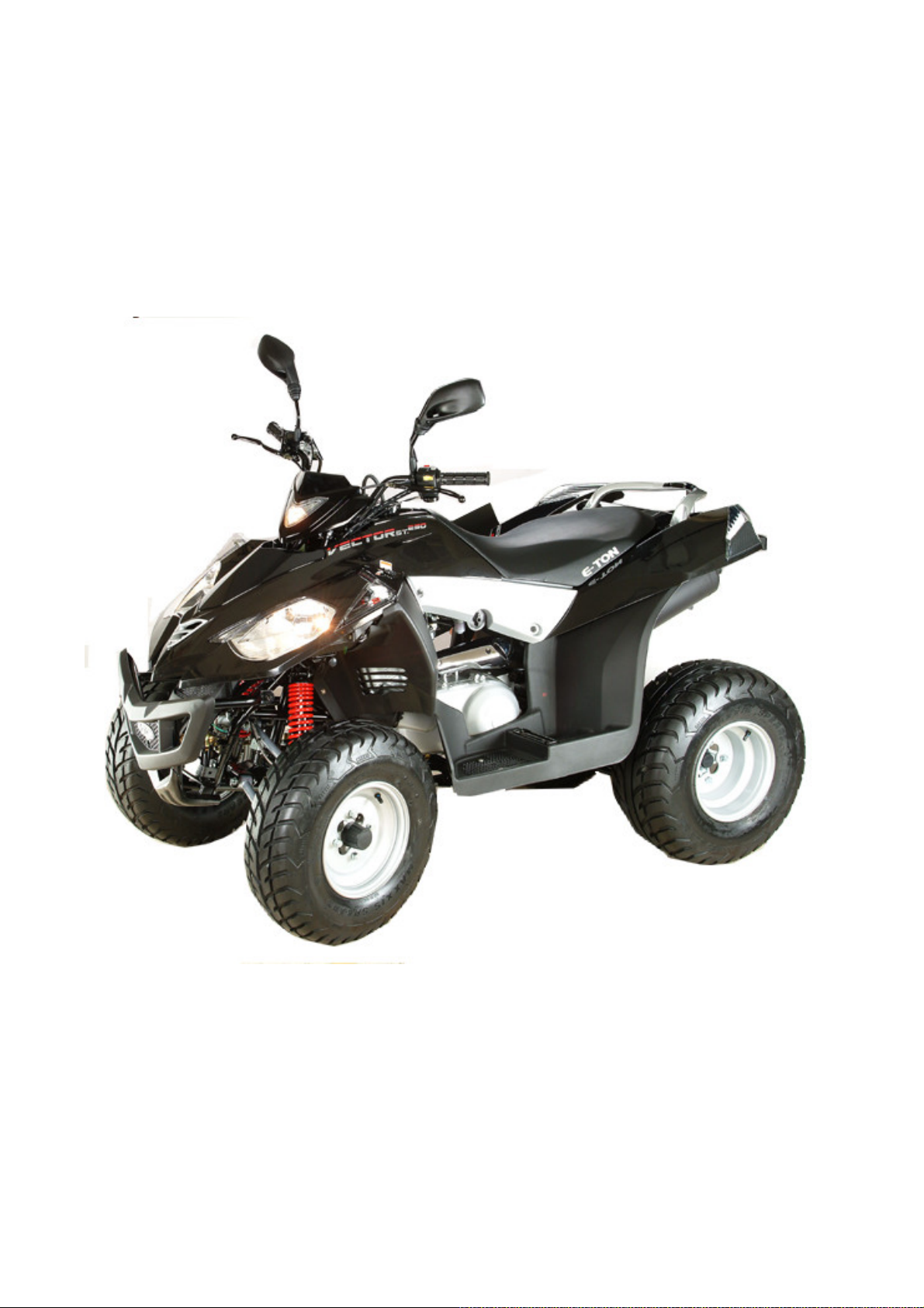
1-4 Serial Number
The frame serial number is stamped on the front of the frame.
The engine serial number is stamped on the left side of the crankcase.
Frame serial number
8
Page 9

1-5 Torque Values
STANDARD
● 5 mm bolt and nut
5 N.m (3.5 lbf.ft)
● 6 mm bolt and nut
● 8 mm bolt and nut
●10 mm bolt and nut
●12 mm bolt and nut
ENGINE
● Cylinder head nut
● Spark plug
● Cylinder head bolt
● Alternator bolt
FRAME
● Handlebar upper holder bolt
● Throttle housing cover screw
● Steering shaft nut
● S te ering shaft holder bolt
10 N.m (7.2 lbf.ft)
22 N.m (16 lbf.ft)
35 N.m (25 lbf.ft)
55 N.m (40 lbf.ft)
38 N.m (27.4 lbf.ft)
12 N.m (8.9 lbf.
15 N.m (10.1 lbf.ft)
8 N.m (5.9 lbf.ft)
24 N.m (17.7 lbf.ft)
4 N.m (2.9 lbf.ft)
50 N.m (36.9 lbf.ft)
33 N.m (24 lbf.ft)
ft)
● Wheel rim bolt
● Tie rod lock nut
● King pin nut
● Handlebar lo wer holder nut
● Front wheel bolt
● Front axle castle nut
● Front brake arm nut
● Rear brake arm nut
● Rear axl e castle nut
● Rear wheel bolt
● Exhaust muffler mounting bolt
● Engine hanger bolt
● Rear axle holder bolt
Nuts, Bolts Tightness
● Swing arm pivot nut
● Rear shock absorber mounting nut
18 N.m (13.3 lbf.ft)
35 N.m (25.8 lbf.ft)
40 N.m (29 lbf.ft)
40 N.m (29.5 lbf.ft)
24 N.m (17.7 lbf.ft)
40-60 N.m (30-45 lbf.ft)
4 N.m (3.0 lbf.ft)
7 N.m (5.2 lbf.ft)
40-60 N.m (30-45 lbf.ft)
24 N.m (17.7 lbf.ft)
30 N.m (22.1 lbf.ft)
30 N.m ( 22 lbf.ft)
90 N.m (65 lbf.ft)
90 N.m (65 lbf.ft)
45 N.m (33 lbf.ft)
Perform periodical maintenance in accord with the Periodical Maintenance Schedule Check if all
bolts and nuts on the frame are tightened securely.
Check all fixing pins, snap rings, hose clamp, and wire holders for security.
Page 10

1-6 Special Tools
For Frame
1. Adjustable Hook Spencer
(E1105-LRA0-FT1)
Purpose: Adjusting of suspension
2. Ball Joint Puller(E0205-LRA0-FT1)
Purpose: Taking out the ball joint from front knuckle as repairing.
10
Page 11
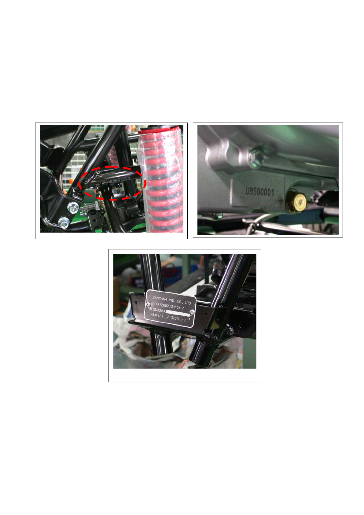
For Engine
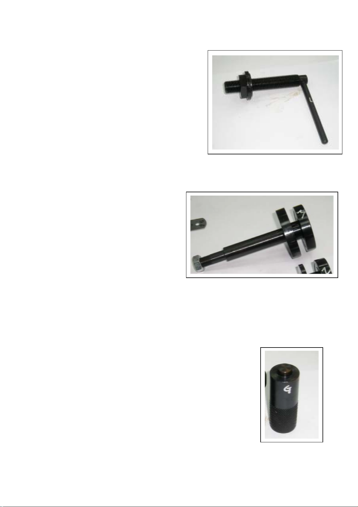
1. TACKING ACG FLY WHEEL TOOL
(C1110-RB1-FT1)
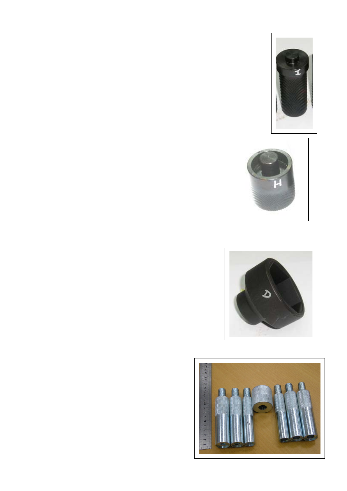
2. COUNTER SHIFT IMPLEMENT (I1003-RB1-FT1)
3. ADJUST TAPPET IMPLEMENT
(A4721-HMA-FT1)
4. SLEEVE OF FABRICATING TRANSMISSION
SHAFT & OIL SEAL (I1202-RB1-FT1)
11
Page 12

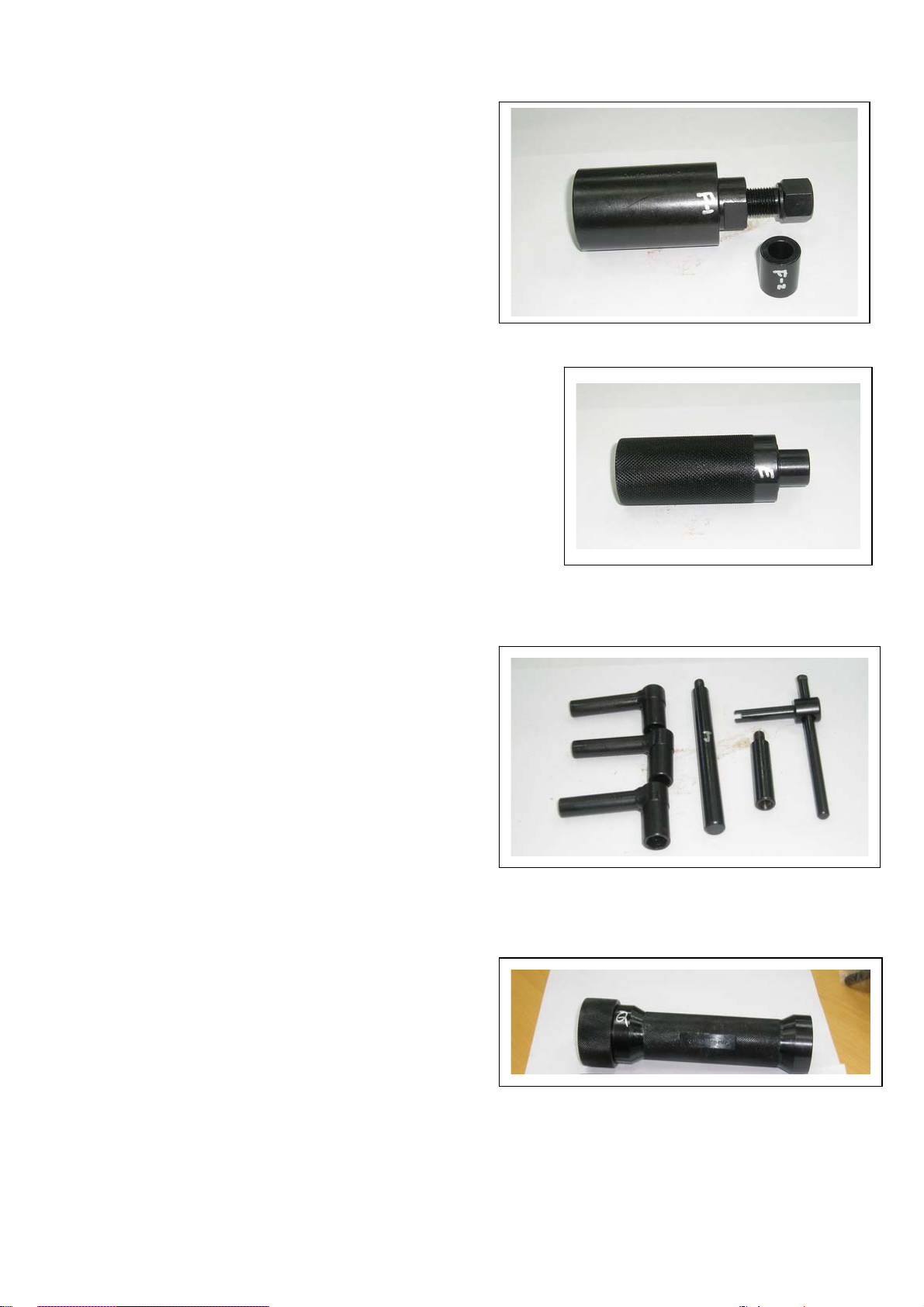
5. SLEEVE OF FABRICATING L CRANK & OIL
SEAL (I1201-HMA-FT1)
6. TAKING 6205 BRG. TOOL (I6150-6205-FT1)
7. 6205 BRG. KNOCK TOOL (I6150-6205-FT2)
8. L CRANK CASE COVER 6006 BRG. FABRICATING TOOL
(I6150-6006-FT1)
12
Page 13
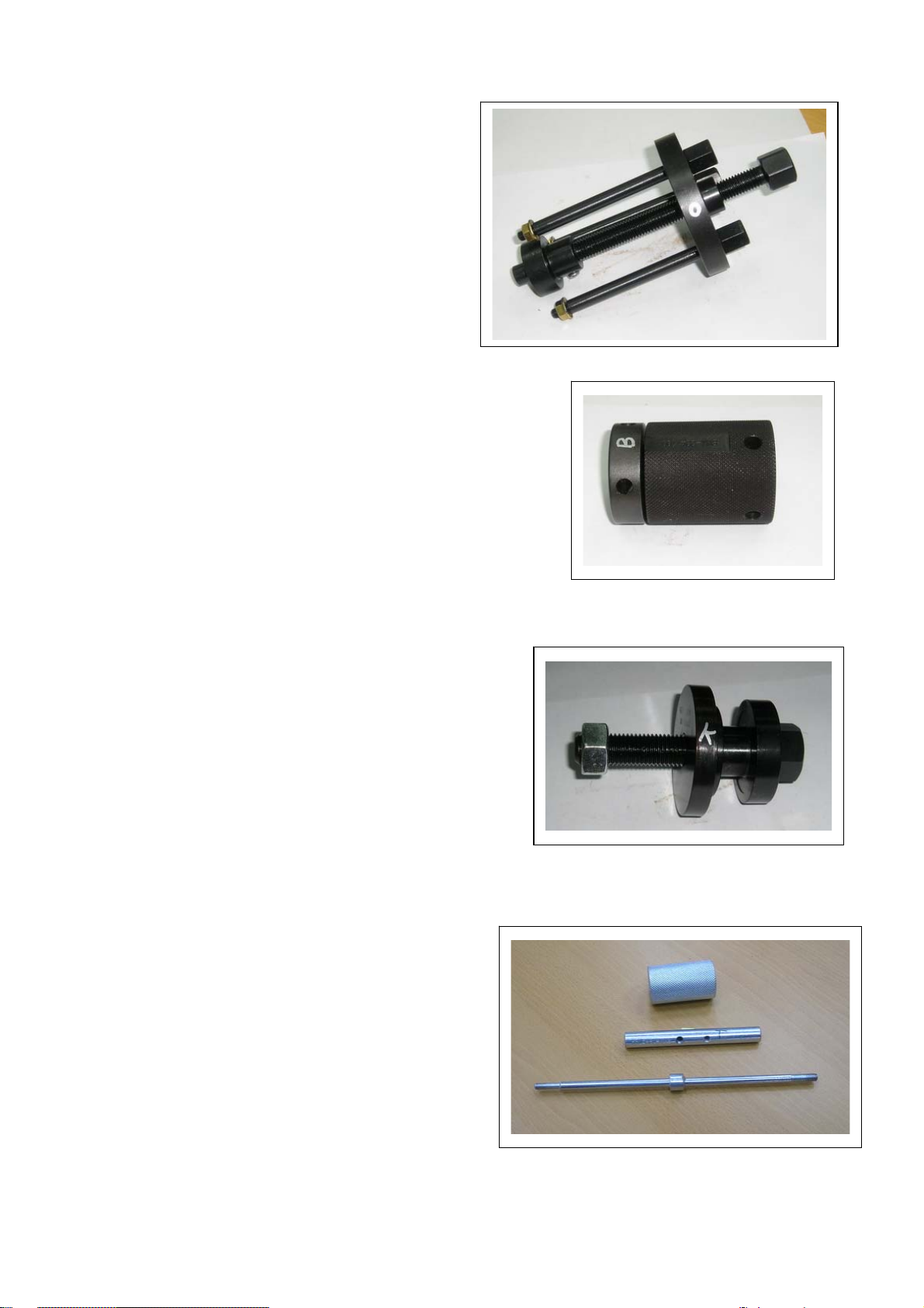
9. FABRICATING R CRANK CASE COVER 6201
BRG. TOOL (I6140-6201-FT1)
10. TAKING BRG. RB1 TOOL (I6150-RB1-FT1)
11. PNEUMATIC TAKING BRG. 6205 TOOL (I6150-6205-FT3)
12. TAKING TAPPET PIN TOOL (A4451-HMA-FT1)
13
Page 14
13. ASSEMBLING DRIVE SHAFT TOOL
(B3411-RB1-FT1)
14. TAKING TRANSMISSION SHAFT BRG. 6305
TOOL (I6100-6305-FT1)
15. KNOCKING BRG.(6901) WATER PUMP IMPLEMENT
(I1001-KJ9-FT1)
14
Page 15
16. KNOCKING WATER PUMP OIL SEAL IMPLEMENT (INSIDE)
(I1205-KF0-FT1 )
17. KNOCKING WATER PUMP OIL SEAL(IRON) IMPLEMENT
(A9217-H9A-FT1)
18. TAKING & LOCKING SPECIAL NUT 36MM SLEEVE
(I0202-HMA-FT1)
19. TAKING & FABRICATING IN. VALVE TOOL
(A4711-HMA-FT1)
15
Page 16

20. TAKING BRG. 62040 LARGE-SIZE TOOL
(I6100-6204-FT3 )
21. ALL-PURPOSE FIXER (B2101-HMA-FT1)
22. KNOCKING BRG.(6204) IMPLEMENT
(I6100-6204-FT2)
16
Page 17

2. MAINTENANCE
2-1 Maintenance Data 2-8 Idle Speed
2-2 Maintenance Schedule 2-9 Drive Chain
2-3 Fuel Tube 2-10 Brake System
2-4 Throttle Operation 2-11 Wheels And Tires
2-5 Throttle Cable Adjustment 2-12 Steering Shaft Holder Bushing
2-6 Air Cleaner 2-13 Toe-In
2-7 Spark Plug
2-1 Maintenance Data
SPECIFICATION
SPARK PLUG
SPARK PLUG GAP 0.8 mm
RECOMMENDED SPARK PLUGS NGK CR8E
THROTTLE LEVER FREE PLAY 5-10 mm
IDLE SPEED 1700±100 rpm
BRAKE LEVER FREE PLAY 15-25 mm
DRIVE CHAIN SLACK 10-25 mm
TOE-IN 5±10 mm
TORQUE VALUES
SPARK PLUG 12-19 N.m
TIE-ROD LOCK NUT 35-43 N.m
ENGINE OIL 1.4 Liter (1.2Liter for change)
GEAR LUBRICATION OIL 750cc (650cc for change)
17
Page 18

2-2 Maintenance Schedule
The internal maintenance in the following table is based on average riding, normal conditions.
Riding in unusually dusty areas, require more frequent servicing.
300KM Every Every Every Every Notes
1 Month 3 Months 6 Months 1 Year 2 Years
Fuel Lines I I R
Throttle Operation I I
Air Filter I C R
Fuel Filter R
Spark Plug I I R
Drive Chain I, L Lubricate for every 1 month
Brake Shoes I
Brake System I I
Brake Fluid I R
Nuts, Bolts & Fasteners I
WHEEL/TIRES I I
Wheels I I
Steering System I I
Suspension System I I
C.V.T Drive belt I R
Transmission Oil R Replace for every 3,000km or 6 Months
Engine Oil R Replace for every 3,000km or 6 Months
Battery I I,C I,C
Oil Filter (Screen) C C
Valve Clearance I I
Coolant I I R
Cooling Fan I I
Carburetor (Idle Speed) I I
Choke I
Note – I: Inspect and Clean, Adjust, Lubricate or Replace, if necessary
C: Clean L: Lubricate R: Replace
2-3 Fuel Tube
Inspect the fuel lines for deterioration, damaging or
leakage and replace if necessary.
18
Page 19
2-4 Throttle Operation
Inspect for smooth throttle lever full opening and automatic
full closing in all steering positions.
Inspect if there is no deterioration, damage or kink in the
throttle cable, replace it if necessary.
Check the throttle lever, free play is 5-10 mm at the tip of the
throttle lever.
Disconnect the throttle cable at the upper end.
Lubricate the cable with commercially lubricant to prevent
premature wear.
2-5 Throttle Cable Adjustment
Slide the rubber cap of the adjuster off the throttle
Housing, loosen the lock nut and adjust the free play
of the throttle lever by turning the adjuster on the throttle housing.
Inspect the free play of the throttle lever.
Throttle
2-6 Air Cleaner
Please remove the four hooks, and then disassemble
two screws inside the air cleaner case.
Pull out the air filter element from the air cleaner case.
Washing the element in non-flammable solvent, squeeze
out the solvent thoroughly.
Let it dry.
Soak the filter element in gear oil and then squeeze
out the excess oil.
Install the every component into air cleaner in the reverse order of
removal.
Note: for more detail please check chapter 5-10
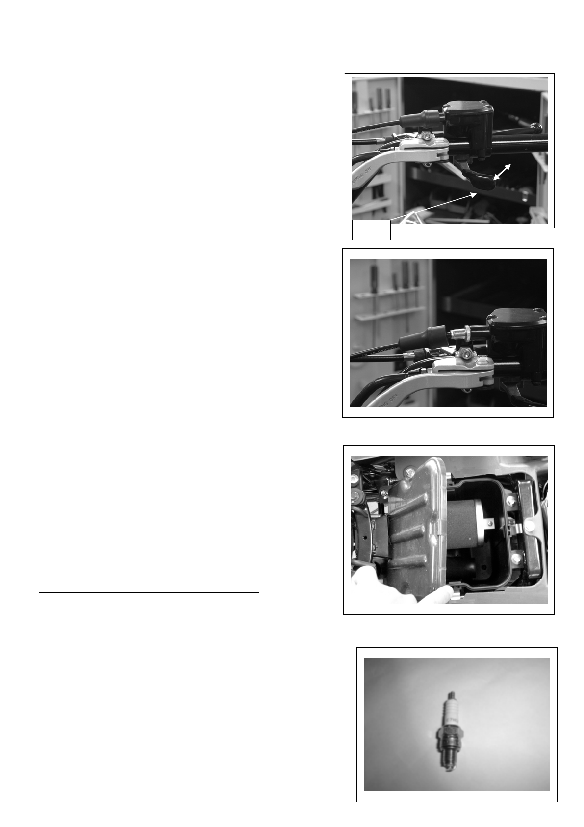
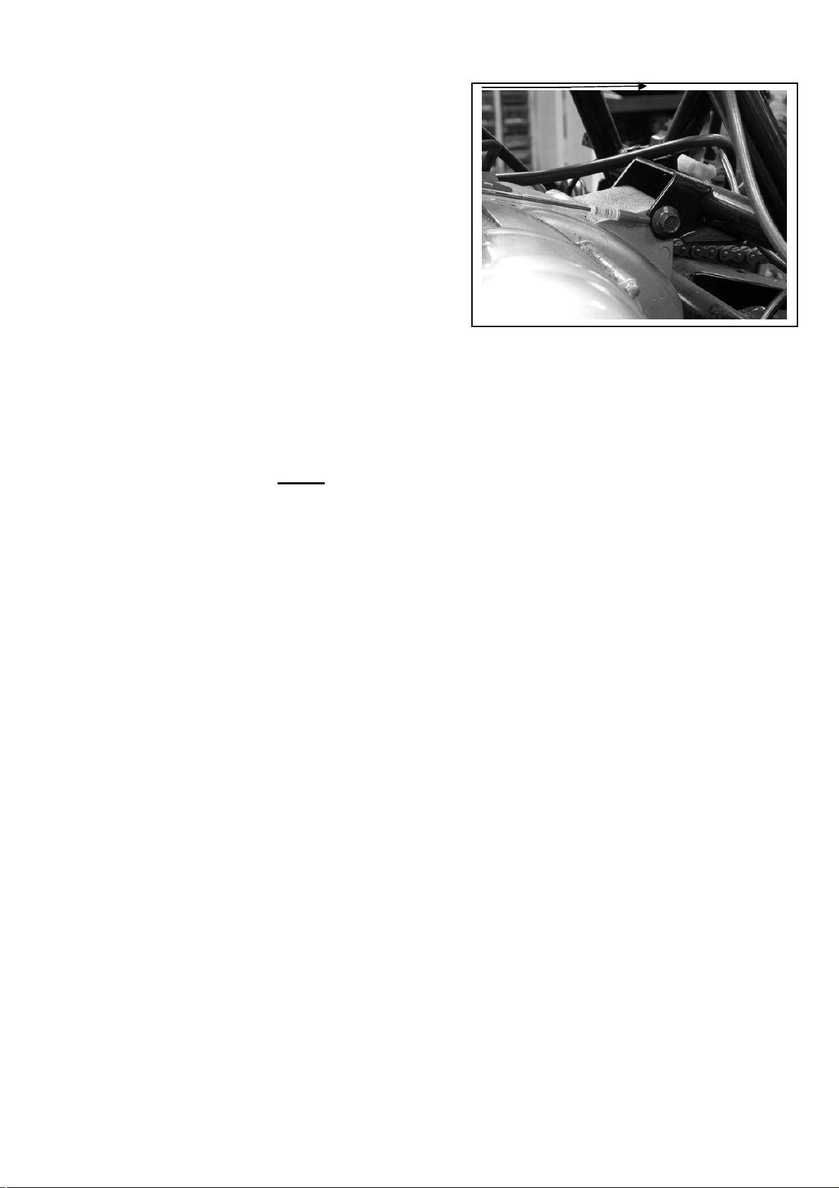
2-7 Spark Plug
This spark plug is located at the front of the engine.
Disconnect the spark plug cap and unscrew the spark plug.
Check the condition of spark plug electrodes wear.
19
Page 20

Change a new spark plug if the electrodes and insulator tip appear unusually fouled or burned.
Discard the spark plug if there is apparent wear or if the insulator is cracked or chipped.
The spark plug gap shall keep in 0.8mm
With the sealing washer attached, thread the spark plug in by hand to prevent crosses threading.
Tighten the spark plug with 1.0~1.2kgf-m
2-8 Idle Speed
Connect an engine speed meter.
Warm up the engine, 10 minutes are enough.
Turn the idle-speed adjust screw on the carburetor to obtain the idle speed. “Turn in” (clockwise) will
get higher speed. “Turn out” (counter clockwise) will get lower speed.
IDLE SPEED: 1700±100 rpm
2-9 Drive Chain
Stopping the ATV and shift the transmission into neutral(N) .
Measure the drive chain slack midway between the
sprockets.
Chain slack =15~25mm (5/8~1 inch)
Adjust the chain slack.
Loosen the lock nuts and turn drive chain adjusting nuts
until get the correct slack.
Tighten the axle holder bolts.
Torque = 90N.m (65 lbf.ft)
When the drive chain becomes very dirty, it should be removed, cleaned and lubricated by specify lubricator.
Please use special chain oil to lubricate the drive chain.
Clean the drive chain with kerosene and wipe it dry.
Inspect the drive chain for any possible wearing or damaging.
Replace the chain, if it is worn excessively or damaged.
Inspect the sprocket teeth, if it is excessive wearing or damaging,
please replace it.
20
Page 21
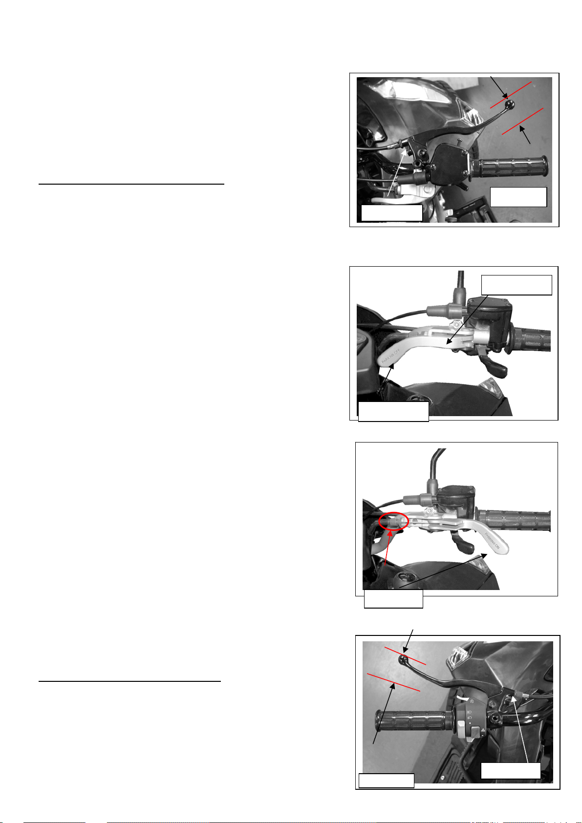
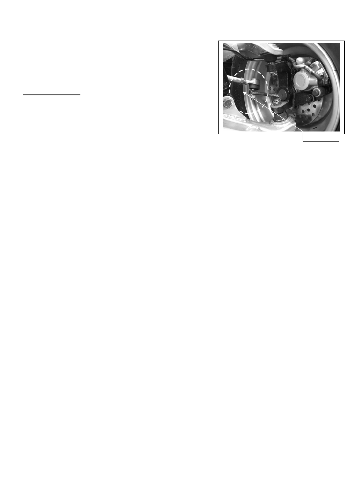
2-10 Brake System
Inspect the front brake lever and cable for excessive play or other
damage.
Replace or repair if necessary.
Measure the brake lever free play at the end of the brake lever trip.
Front Brake lever free play is 15-25 mm.
Turn the parking brake to the left side is “parking off”, while
turn to right side is “parking on”. As you found out the
parking brake which has been decreased its brake ability, you
might screw the adjustable nut to modify the clearance of
brake shoe to the correct position. Also, another method of
adjustment of parking brake, please refer to next page.
Inspect the rear brake lever and cable for excessive
play or other damage.
Replace or repair if necessary.
Measure the rear brake lever free play at the
end of the lever trip.
Rear Brake lever free play is 15-25 mm.
21
Brake lever
Adjustable nut
Parking Brake
Parking Off
Adjustable nut
Parking On
Adjustment
Brake level
Page 22
NOTE:
y The second method to adjust brake level is under the driver
seat and rear brake component.
y In order to avoid a pre-load occurred between brake disk and
lining. After all adjusting of brake system are completed,
please check the small clearance between brake disk and
lining.
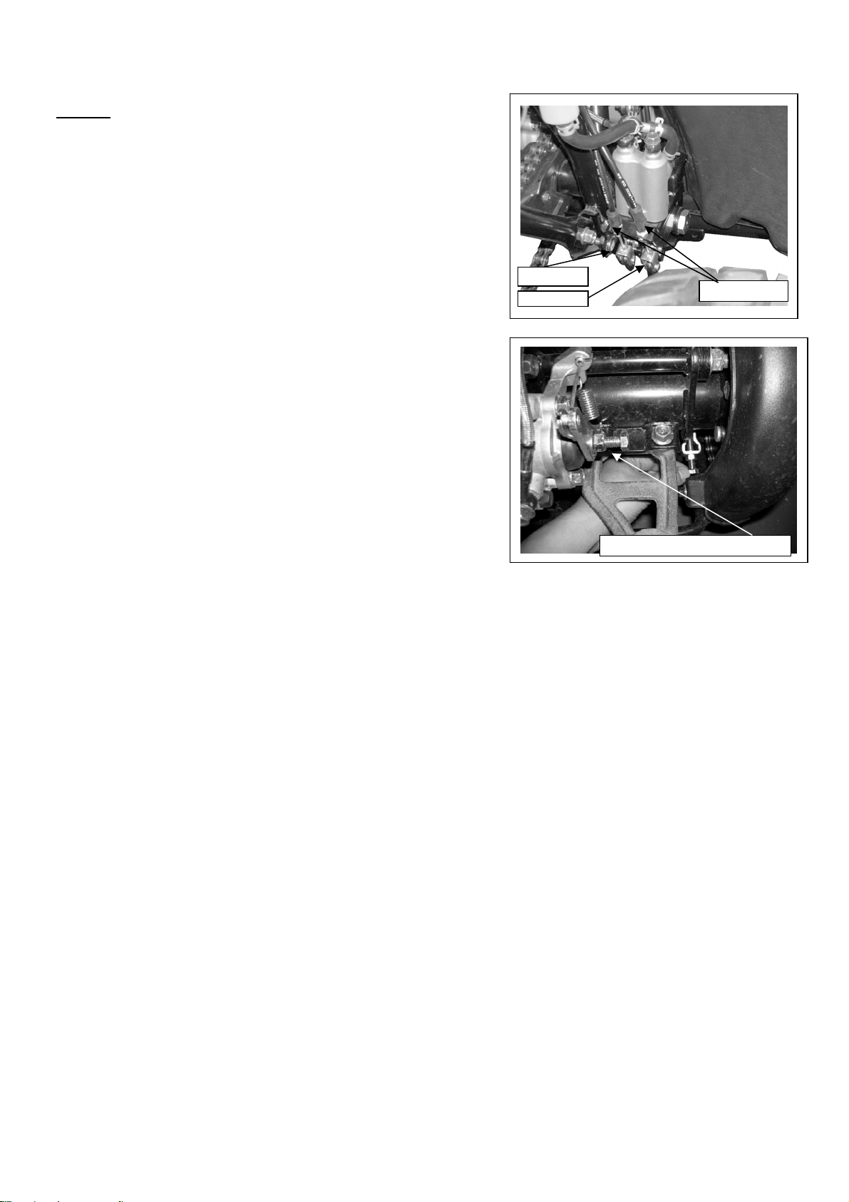
Loosen the adjustable nut near the rear brake caliper. Screw the
adjustable bolt by hand with C.W. turn to the end, then back to a
quarter turn. Tighten the nut to complete the parking brake
adjustment.
Also, as you fount out the brake ability which is a bit insufficient,
you can screw the adjustable nut of parking Brake
.
Rear Brake
Adjustable nut
Parking Brake Adjustable nut
22
Page 23
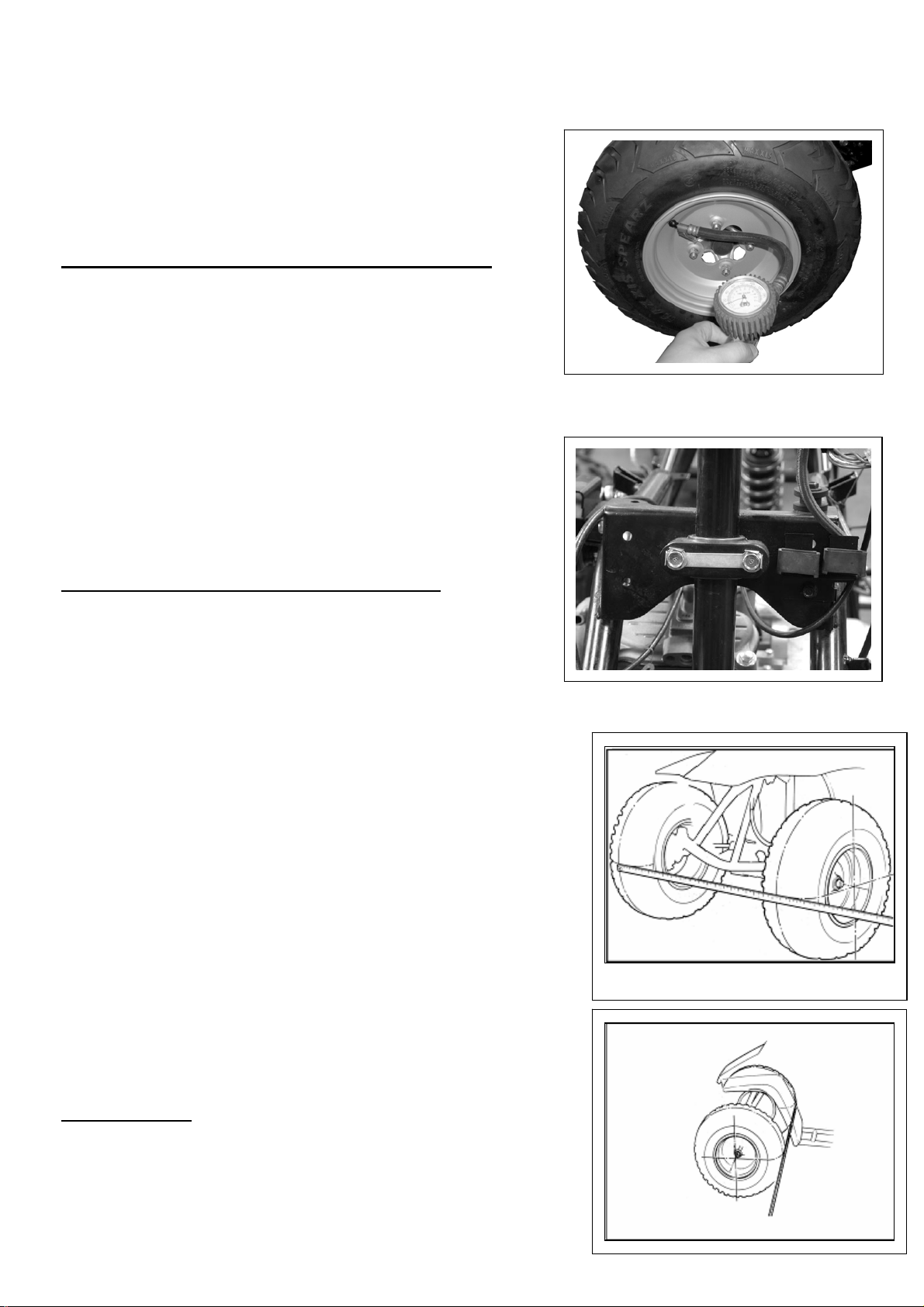
2-11 Wheels And Tires
Inspect the tire surfaces for cuts, nails or other sharp objects.
Check the each tire surface at cold tire condition.
*The standard of tire pressure is 12(0.8) psi ( kgf/cm2)
2-12 Steering Shaft Holder Bushing
Remove the front fender first.
Remove the steering shaft holder and check the steering shaft bushing
for wears or damage.
If the bushing is worn or damaged, please change a new one.
Grease the steering shaft bushing and install the parts
in the reverse order of removal.
Torque: steering shaft holder bolt: 33 N.m (24 lbf.ft)
2-13 Toe-In
Keep the vehicle on level ground and the front wheels facing straight
ahead.
Mark the centers of the tires to indicate the axle center height.
Measure the distance between the marks.
Carefully to move the vehicle back, let the wheels turn 180 degree,
so the marks on the tires are aligned with the axle center height.
Measure the distance between the marks.
Calculate the difference in the front and rear measurements.
Toe-in: 5±10mm
23
Page 24
If the toe-in is out of standard, adjust it by changing
the length of the tie-rods equally by turning the tie-rod
while holding the ball joint.
Tighten the lock nuts.
Torque: 35-43 N.m
Lock Nuts
24
Page 25
3. ENGINE REMOVE AND INSTALLATION
3-1 General Information 3-3 Engine Installation
3-2 Engine Removal
3.1 General Information
ENGINE SHALL BE REMOVED IN THE CONDITIONS OF NECESSARY REPAIRMENT OR
ADJUSTMENT TO THE TRANSMISSION AND COMBUSTION SYSTEM ONLY
3-2 Engine Removal
Before removing engine, you need to remove all of components such as seat, front and back fender,
fuel tube, exhaust pipe, carburetor cable and drive chain…etc. You can then see three hanger bolts which have
screwed on engine.
Loosen these three hanger bolts. You have succeeded to remove this engine.
There are some pictures to describe main step of removing engine.
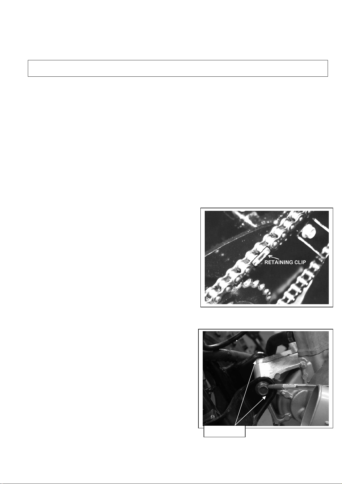
Disconnect the wire connectors. There are three connectors for
carburetor auto-choke, starter motor and generator respectively.
Remove the drive chain cover.
Remove the drive chain retaining clip and master link,
and remove the drive chain.
Hanger bolt
25
Page 26
3-3 Engine Installation
The Engine installation is essentially in the reverse order of removal.
The torque of engine hanger bolt is 30 N.m
Route the wires and cable in reverse order properly.
26
Page 27
4. LUBRICATION SYSTEM
4-1 Mechanism Diagram
4-2 Precautions In Operation
4-3 Troubleshooting
4-5 Engine Oil Strainer Clean
4-6 Oil Pump
4-7 Gear Oil
4-4 Engine Oil
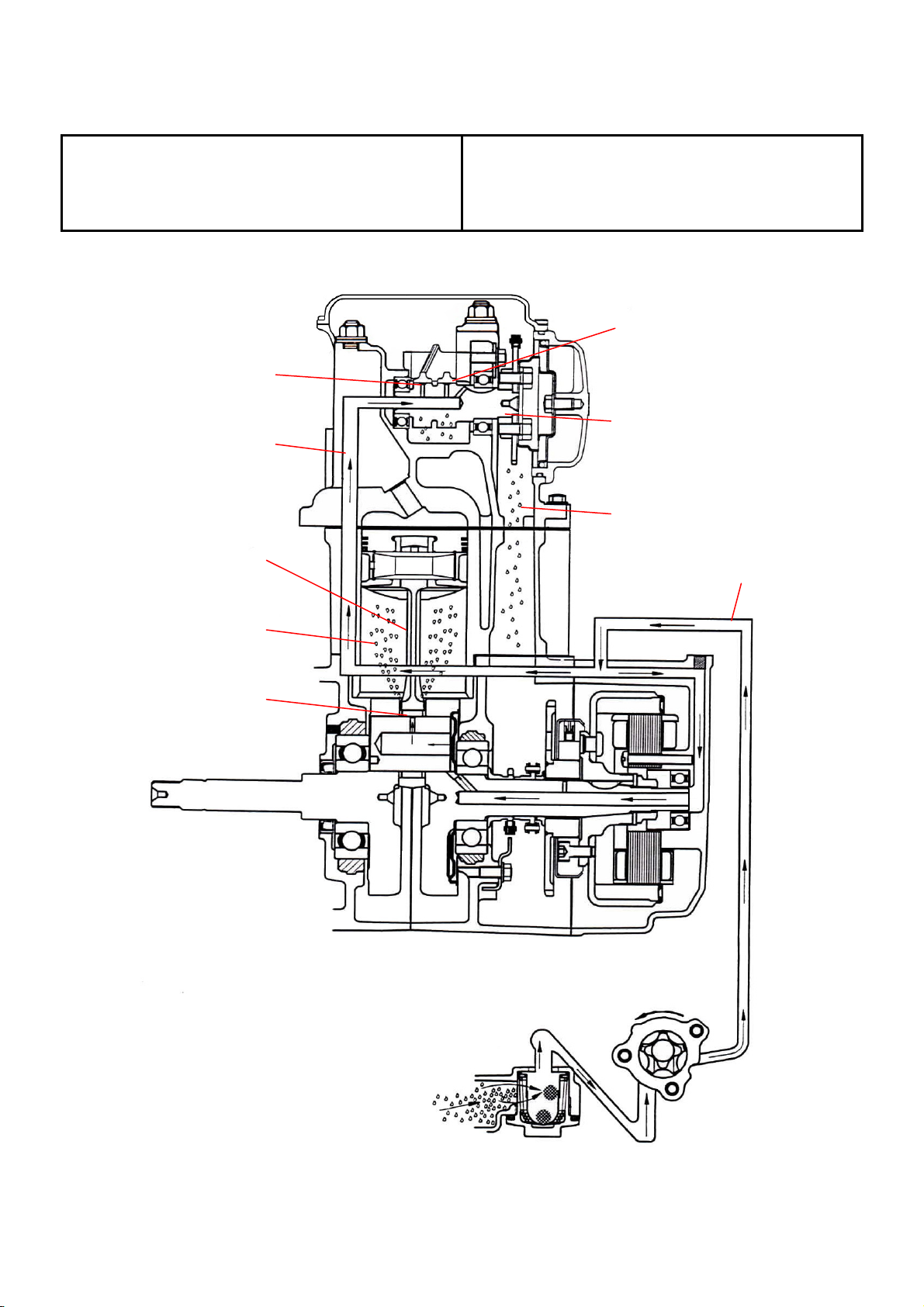
4-1 Mechanism Diagram
Press-In Lubrication
Oil Route
Con-Rod
Valve Rocker Arm
Cam Shaft
Spray Lubrication
Oil Route
Spray Lubrication
Press-In Lubrication
Rotate Direction
Oil Pump
Oil Strainer
27
Page 28
4-2 Precautions In Operation
General Information:
z This chapter contains maintenance operation
for the engine oil pump and gear oil
replacement.
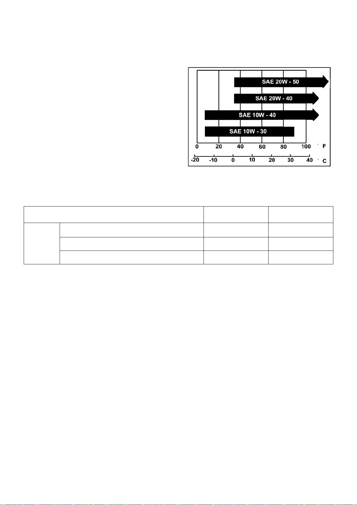
Specifications
Engine oil quantity Disassembly: 1400 c.c.
Change: 1200c.c.
Oil viscosity SAE 10W-30 (Recommended
King serial oils)
Gear oil Disassembly: 750c.c.
Change: 650c.c.
Gear oil viscosity SAE 140
(Recommended SYM Hypoid gear oils)
Items Standard (mm) Limit (mm)
Inner rotor clearance 0.15 0.20
Oil pump
Torque value
Torque value oil strainer cap 1.5~3.0kgf-m
Engine oil drain bolt 1.9~2.5kgf-m
Gear oil drain bolt 1.0~1.5kgf-m
Gear oil join bolt 1.0~1.5kgf-m
Oil pump connection bolt 0.8~1.2kgf-m
Clearance between outer rotor and body 0.15~0.20 0.25
Clearance between rotor side and body 0.04~0.09 0.12
單位:mm
4-3 Troubleshooting
Low engine oil level
y Oil leaking
y Valve guide or seat worn out
y Piston ring worn out
Low oil pressure
y Low engine oil level
y Clogged in oil strainer, circuits or pipes
y Oil pump damage
Dirty oil
y No oil change in periodical
y Cylinder head gasket damage
y Piston ring worn out
28
Page 29
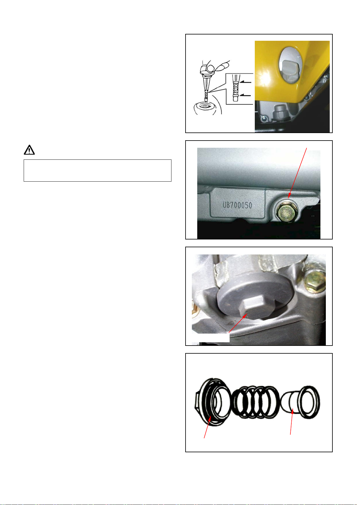
4-4 Engine Oil
Turn off engine, and park the ATV in flat surface
with main stand.
Check oil level with oil dipstick.
So not screw the dipstick into engine as checking.
If oil level is nearly low level, fill out
recommended oil to upper level.
Oil Change
Caution
Drain oil as engine warmed up so that makes sure
oil can be drained smoothly and completely.
Place an oil pan under the ATV, and remove oil
drain bolt.
After drained, make sure washer can be re-used.
Install oil drain bolt.
Drain bolt
Torque value:1.9~2.5kgf-m
4-5 Engine Oil Strainer Clean
Drain engine oil out.
Remove oil strainer and spring.
Clean oil strainer .
Check if O-ring can be re-used.
Install oil strainer and spring.
Install oil strainer cap.
Torque value:1.5~3.0kgf-m
Add oil to crankcase (oil viscosity SAE 10W-30)
Recommended using King serial oil.
Engine oil capacity: 1200c.c. when replacing
Install dipstick, start the engine for running
several minutes.
Turn off engine, and check oil level again.
Check if engine oil leaks.
Oil strainer cap
O-ring
29
Oil strainer
Page 30
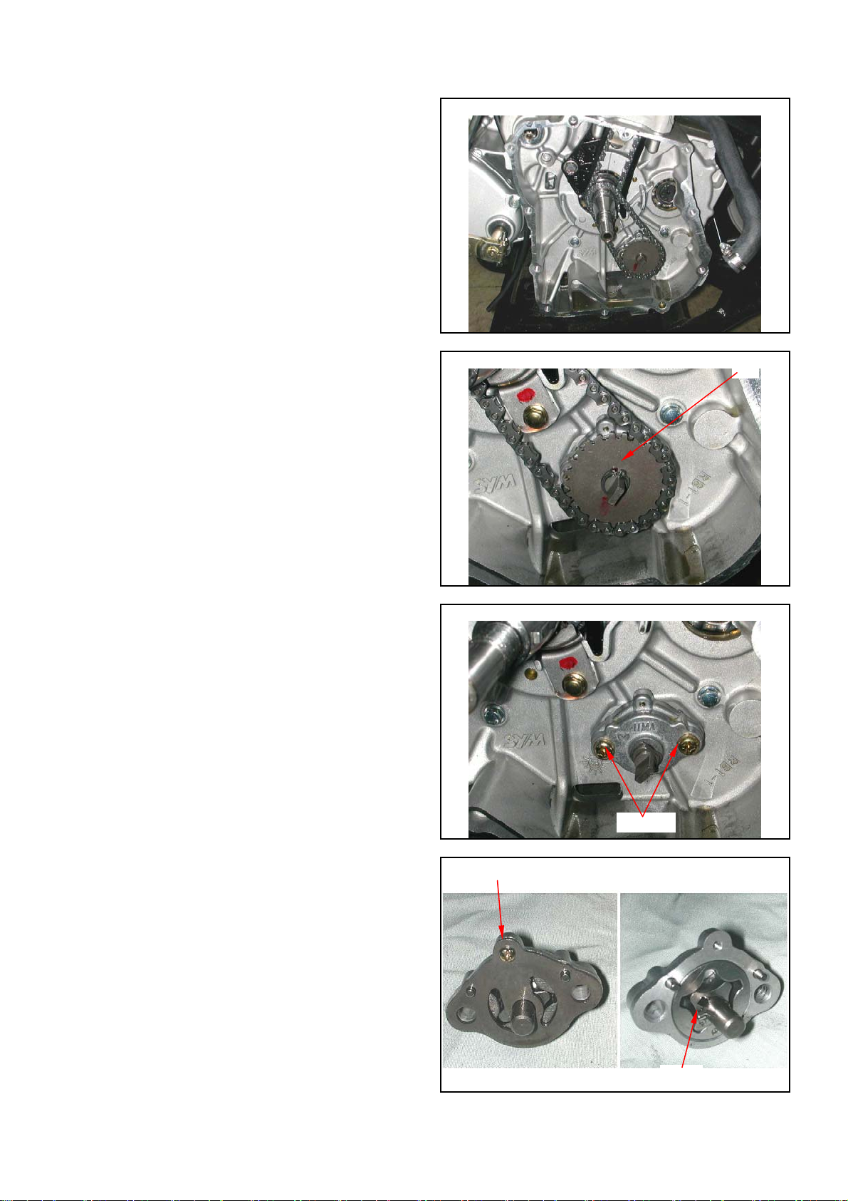
4-6 Oil Pump
Oil Pump Removal
Remove generator and starting gear. (Refer to
chapter 10) 。
Remove cir clip and take out oil pump driving
chain and sprocket.
Make sure that pump shaft can be rotated freely.
Remove 2 screws on the oil pump, and then
remove oil pump.
Oil Pump Disassembly
Remove the screws on oil pump cover and
remove the cover.
Remove oil pump shaft roller and shaft.
Clip
2 screws
1 screw
Roller
30
Page 31

Oil Pump Inspection
Check the clearance between oil pump body and
outer rotor.
Limit: 0.25 mm
Check clearance between inner and outer rotors.
Limit: 0.20 mm
Check clearance between rotor side face and
pump body
Limit: 0.12 mm
Oil Pump Re-assembly
Install inner and outer rotors into the pump body.
Align the indent on driving shaft with that of
inner rotor.
Install the oil pump shaft and roller.
Install the oil pump cover and fixing pins
properly.
Pins
31
Page 32

Tighten the oil pump screw.
Oil Pump Installation
Install the oil pump, and then tighten screws.
Torque value:0.8~1.2kgf-m
Make sure that oil pump shaft can be rotated
freely.
Install oil pump drive chain and sprocket, and
then install cir clip onto oil pump shaft.
Install starting gear and generator.
(Refer to chapter 10)
1 screw
Roller
2 screws
Clip
32
Page 33

4-7 Gear Oil
Gear Oil Change
Remove oil join bolt.
Remove drain bolt and drain gear oil out.
Install the drain bolt after drained.
Torque value: 1.0~1.5kgf-m
Make sure that the drain bolt washer can be re-used.
Add oil to specified quantity from the join hole.
Gear Oil Quantity: 650c.c. when replacing
Make sure that the join bolt washer can be re-used,
and install the bolt.
Start engine and run engine for 2-3 minutes.
Turn off engine and make sure that oil level is in
correct level.
Make sure that no oil leaking.
Gear oil join bolt
Gear oil drain bolt
Page 34

5. FUEL SYSTEM
5-1 Mechanism Diagram
5-6 Throttle Valve
5-2 Precautions in Operation
5-3 Trouble Diagnosis
5-4 Carburetor Remove / Install
5-5 Air Cut-Off Valve
5-1 Mechanism Diagram
5-7 Float Chamber
5-8 Adjustment Of Idle Speed
5-9 Fuel Tank
5-10 Air Cleaner
Fuel tank cap
Fuel unit
Fuel tank
Inlet pipe
Auto fuel cock
Carburetor
Fuel strainer
Page 35

5-2 Precautions In Operation
General Information
Warning
Gasoline is a low ignition point and explosive materials, so always work in a well-ventilated place and
strictly prohibit flame when working with gasoline.
Cautions
y Do not bend off throttle cable. Damaged throttle cable will make unstable drive-ability.
y When disassembling fuel system parts, pay attention to O-ring position, replace with new one as
re-assembly
y There is a drain screw in the float chamber for draining residual gasoline.
y Do not disassemble air cut valve arbitrarily.
Tool
Special service tools
| Vacuum/air pressure pump
| Fuel level gauge
Specification of CARBURETOR
ITEM UA25A
Carburetor diameter Ø22mm
I.D. number PTG 050
Fuel level 14.8mm
Main injector # 110
Idle injector # 35
Idle speed 1700 ± 100rpm
Throttle lever clearance 1~3 mm
Air screw 2 turns
Page 36

5-3 Trouble Diagnosis
Poor engine start
y No fuel in fuel tank
y Clogged fuel tube
y Too much fuel in cylinder
y No spark from spark plug(malfunction of
ignition system )
y Clogged air cleaner
y Malfunction of carburetor chock
y Malfunction of throttle operation
Stall after started
y Malfunction of carburetor chock
y Incorrect ignition timing
y Malfunction of carburetor
y Dirty engine oil
y Air existing in intake system
y Incorrect idle speed
Rough idle
y Malfunction of ignition system
y Incorrect idle speed
y Malfunction of carburetor
y Dirty fuel
Intermittently misfire as acceleration
y Malfunction of ignition system
Late ignition timing
y Malfunction of ignition system
y Malfunction of carburetor
Power insufficiency and fuel consuming
y Fuel system clogged
y Malfunction of ignition system
Mixture too lean
y Clogged fuel injector
y Vacuum piston stick and closed
y Malfunction of float valve
y Fuel level too low in float chamber
y Clogged fuel tank cap vent
y Clogged fuel filter
y Obstructed fuel pipe
y Clogged air vent hose
y Air existing in intake system
Mixture too rich
y Clogged air injector
y Malfunction of float valve
y Fuel level too high in float chamber
y Malfunction of carburetor chock
y Dirty air cleaner
Page 37

5-4 Carburetor Remove / Install
Removal
Drain out fuel in the float chamber.
Loosen the choke cable fixed iron sheet screw from
plate.
Remove the choke cable.
Disconnect the fuel hose.
Release the clamp strip of air cleaner.
Remove the carburetor upper parts from the
carburetor.
Release the 2 nuts of carburetor insulator, and then
remove the carburetor.
Installation
Install in reverse order of removal procedures.
Drain bolt
Vacuum pipe
1 screw
Choke cable
Fuel pipe
Clamp
2 nuts
Page 38

5-5 Air Cut-Off Valve
A
Disassembly
Remove 2 screws.
Remove air cut-off valve cover, spring and valve.
Inspection
Check the valve is in normal.
If the valve is in normal, it will restrict air-flow.
If air-flow is no restricting, replace carburetor
assembly.
Check the vacuum pipe o-ring is in normal.
Assembly
Install in reverse order of removal procedures.
2 screws
O-ring
ir cut-off valve
Spring
Cover
Page 39

5-6 Throttle Valve
p
Disassembly
Remove carburetor upper parts, and then remove
throttle valve and throttle cable.
Disconnect the throttle cable from the throttle valve
and remove the valve spring.
Remove the fuel needle clamp and fuel needle.
Assembly
Place the fuel needle onto the throttle valve and clip it
with needle clamp.
Install the sealed cap, carburetor upper part, and
throttle valve spring.
Connect the throttle valve cable to the throttle valve.
Install the throttle valve into the carburetor body.
Throttle valve
Throttle
Spring
Needle clam
Fuel needle clip
Fuel needle
Caution
Align the groove inside the throttle valve with the
throttle stopper screw of the carburetor body.
Tighten the carburetor upper part.
Adjust the free play of throttle valve cable.
Page 40

5-7 Float Chamber
Disassembly
Remove 3 mounting screws and remove float
chamber cover.
Remove the fuel level plate, float pin, float and float
valve.
Inspection
Check float valve and valve seat for damage,
blocking.
Check float valve for wearing, and check valve seat
face for wear, dirt.
Fuel level plate
3 Screws
Float valve
Pin
Pin
Caution
In case of worn out or dirt, the float valve and
valve seat will not tightly close causing fuel level
to increase and as a result, fuel flooding. A worn
out or dirty float valve must be replaced with a
new a new one.
Float valve
Page 41

Remove main jet, needle jet holder, needle jet, slow
jet and air adjustment screw.
Caution
Take care not to damage jets and adjust screw.
y Before removing adjustment screw, turn it all
the way down and note the number of turns.
y Does not turn adjust screw forcefully to avoid
damaging valve seat face.
Clean jets with cleaning fluid. Then use compressed
air to blow the dirt off.
Blow carburetor body passages with compressed air.
Assembly
Install main jet, needle jet holder, needle jet, slow jet
and air adjustment screw.
Needle jet holder
Needle jet
Main jet
Slow jet
Air adjustment screw
Caution
Set the air adjustment screw in according to
number of turns noted before it was removed.
Install the float valve, float, and float pin.
Checking fuel level
Caution
y Check again to ensure float valve, float for
proper installation.
y To ensure correct measurement, position the
float meter in such a way so that float chamber
face is vertical to the main jet.
Fuel level: 14.8mm
Installation of carburetor
Install carburetor in the reverse order of removal.
Following adjustments must be made after
installation.
․Throttle cable adjustment.
․Idle adjustment
Float gauge
Throttle adjustment screw
Lock nut
Page 42

5-8 Adjustment Of Idle Speed
Caution
y Inspection & adjustment for idle speed have to
be performed after all parts in engine that
needed adjustment have been adjusted.
y Idle speed check and adjustment have to be
done after engine is being warm up. (It is
enough that operates engine from stop to
running for 10 minutes.)
Park the ATV warm up engine.
Connect tachometer (the wire clamp of tachometer
is connected to the high tension cable).
Turn the throttle valve stopper screw to specified
idle speed.
Specified idle speed: 1700 ± 100 rpm
Emission adjustment in idle speed
Warm up the engine for around 10 minutes and
then conduct this adjustment.
1. Connect the tachometer onto engine.
2. Adjust the throttle valve stopper screw and let
engine runs in 1600±100 rpm.
3. Insert the exhaust sampling pipe of exhaust
analyzer into the front section of exhaust pipe.
Adjust the air adjustment screw so that
emission value in idle speed is within standard.
4. Slightly accelerate the throttle valve and
release it immediately. Repeat this for 2~3
times.
5. Read engine RPM and value on the exhaust
analyzer. Repeat step 2 to step 4 procedures
until measured value within standard.
Emission standard CO: below 0,8~1.5%
HC: below 900ppm
Ignition cable
Stopper screw
Air adjustment screw
Page 43

5-9 Fuel Tank
V
Fuel unit removal
Open the seat.
Remove the front cover and fuel tank.
Remove the side covers and lower side covers.
Remove the front fender.
(Covers remove please refer chapter 13)
Disconnect fuel unit coupler.
Remove fuel unit (4 bolts).
4 bolts
Caution
․Do not bend the float arm of fuel unit
․Do not fill out too much fuel to fuel tank.
Fuel unit inspection (Refer to electrical equipment
chapter 17).
Fuel unit installation
Install the gauge in the reverse order of removal.
Caution
Do not forget to install the gasket of fuel unit or
damage it.
Fuel tank removal
Open the seat.
Remove the front cover and fuel tank.
Remove the side covers and lower side covers.
Remove the front fender.
(Covers remove please refer chapter 13)
Disconnect fuel unit coupler.
Remove fuel unit (4 bolts).
Remove the fuel tube.
Remove the vacuum tube.
Remove fuel tank front and rear side 4 bolts, and then
remove fuel tank.
Installation
Install the tank in the reverse order of removal.
Coupler
acuum tube
FRONT
REAR
Fuel tube
4 bolts
Page 44

5-10 Air Cleaner
Removal
Loosen the clamp strip of air cleaner and carburetor,
and then remove the vapor hose.
Loosen the clamp strip of air cleaner, and then
remove the air cleaner vapor hose.
Remove the air cleaner (4 bolts).
Installation
Install the tank in the reverse order of removal.
Cleaning air cleaner element
Remove the air cleaner cover (4 catch hooks).
Remove element mounting screw.
Loosen the clamp strip of air cleaner element, and
then remove the air cleaner element.
Clean the element with non-flammable or high-flash
point solvent and then squeeze it for dry.
Caution
Clamp
Clamp
4 bolts
4 hooks
Never use gasoline or acid organized solvent to
clean the element.
Soap the element into cleaning engine oil and then
squeeze it out. Install the element onto the element
seat and then install the air cleaner cover.
Clamp
1 screw
Page 45

6. CYLINDER HEAD/VALVE
6-1 Mechanism Diagram
6-2 Precautions In Operation
6-3 Troubleshooting
6-4 Cylinder Head Removal
6-5 Cylinder Head Inspection
6-1 Mechanism Diagram
1.0~1.4kgf-m
6-6 Valve Stem Replacement
6-7 Valve Seat Inspection And Service
6-8 Cylinder Head Reassembly
6-9 Cylinder Head Installation
6-10 Valve Clearance Adjustment
1.0~1.4kgf-m
1.0~1.4kgf-m
1.0~1.4kgf-m
0.7~1.1kgf-m
1.0~1.4kgf-m
3.6~4.0kgf-m
2.4~3.0kgf-m
1.0~1.2kgf-m
1.0~1.2kgf-m
Page 46

6-2 Precautions In Operation
General Information
y This chapter is contained maintenance and service for cylinder head, valve, and camshaft as well as
rocker arm.
y Cylinder head service can be carried out when engine is in frame.
Specification of CYLINDER HEAD
Item Standard Limit
Compression pressure 12±2 kg/cm2 ---
Camshaft Height of cam lobe
ID of valve rocker arm 11.982~12.000 12.080
Rocker arm
OD of valve rocker arm shaft 11.966~11.984 11.936
OD of valve stem
ID of valve guide 5.000~5.012 5.030
Clearance between
valve stem and guide
Valve
Free length of valve
spring
Valve seat width 3.400 4.000
Valve clearance
Tilt angle of cylinder head --- 0.050
Torque Value
Cylinder head cover bolt 1.0~1.4kgf-m
Exhaust pipe stud bolt 2.4~3.0kgf-m
Cylinder head bolt 1.0~1.4kgf-m
Cylinder head Nut 3.6~4.0kgf-m
Sealing bolt of cam chain auto-tensioner 0.8~1.2kgf-m
Bolt of cam chain auto-tensioner 1.2~1.6kgf-m
Cylinder side cover bolt 1.0~1.4kgf-m
Cam sprocket bolt 1.0~1.4kgf-m
Tappet adjustment screw nut 0.7~1.1kgf-m
Spark plug 1.0~1.2kgf-m
Tools
Special service tools
Valve reamer: 5.0mm
Valve guide driver: 5.0mm
Valve spring compressor
Intake 5.90 5.85
Exhaust 5.70 5.65
Intake 4.975~4.990 4.900
Exhaust 4.950~4.975 4.900
Intake 0.010~0.037
Exhaust 0.025~0.062
Intake 38.700 35.200
Exhaust 40.400 36.900
Intake 0.10±0.02mm Exhaust 0.15±0.02mm -
0.080
0.100
Page 47

6-3 Troubleshooting
Engine performance will be affected by troubles on engine top parts. The trouble usually can be determined or by
performing cylinder compression test and judging the abnormal noise generated.
Low compression pressure
1. Valve
y Improper valve adjustment
y Burnt or bent valve
y Improper valve timing
y Valve spring damage
y Valve carbon deposit.
2. Cylinder head
y Cylinder head gasket leaking or damage
y Tilt or crack cylinder
3. Piston
y Piston ring worn out.
High compression pressure
y Too much carbon deposit on combustion chamber or piston head
Noise
y Improper valve clearance adjustment
y Burnt valve or damaged valve spring
y Camshaft wear out or damage
y Chain wear out or looseness
y Auto-tensioner wear out or damage
y Camshaft sprocket
y Rocker arm or rocker arm shaft wear out
Page 48

6-4 Cylinder Head Removal
g
Remove engine. (Refer to chapter 5)
Remove the inlet pipe (2 nuts).
Remove 1 bolt of thermostat and then remove the
thermostat.
Remove hole bolt and spring for the cam chain
tensioner.
Loosen 2 bolts, and then remove tensioner.
Remove thermostat (2 bolts).
Remove Air Injection system (AI) pipe mounting
bolts.
Remove spark plug.
Remove the side cover mounting blots of cylinder
head, and then take out the side cover.
2 nuts
Tensioner bolts
4 bolts
3 bolts
Thermostat bolts
Spark plu
Page 49

Remove left crankcase cover, and turn the
p
Turn the drive face, and align the timing mark on
the sprocket with that of cylinder head, piston is at
TDC position.
Remove cam sprocket bolts and then remove the
sprocket by prying chain out.
Remove cam shaft setting plate (1 bolt).
Remove rocker arm shafts and rocker arms.
Special Service Tool:
Rocker arm and cam shaft puller
Remove cam shafts.
Special Service Tool:
Rocker arm and cam shaft puller
2 bolts
Timing mark
Cam shaft setting plate
Rocker arm shafts
Rocker arm shaft and
cam shaft
uller
Cam shafts
Rocker arm
shaft and cam
Page 50

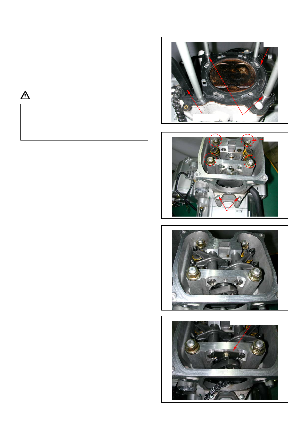
Remove the 2 cylinder head mounting bolts from
cylinder head right side, and then remove 4 nuts and
washers from cylinder head upper side.
Remove the cylinder head.
Remove cylinder head gasket and 2 dowel pins.
Remove chain guide.
Clean up residues from the matching surfaces of
cylinder and cylinder head.
2 bolts
4 Nuts
Gasket
Caution
y Do not damage the matching surfaces of
cylinder and cylinder head.
y Avoid residues of gasket or foreign materials
falling into crankcase as cleaning.
Use a valve cotter remove & assembly tool to press
the valve spring, and then remove valves.
Caution
y In order to avoid loosing spring elasticity, do
not press the spring too much. Thus, press
length is based on the valve cotter in which can
be removed.
Chain guide
Valve cotter remove
Inlet valve
Dowel pins
Inner spring
Spring retainer
Special Service Tool:
Valve cotter remove & assembly tool
Exhaust valve
Outer spring
Cotter
Page 51

V
Remove valve stem seals.
Clean carbon deposits in combustion chamber.
Clean residues and foreign materials on cylinder
head matching surface.
Caution
alve stem seals
Do not damage the matching surface of cylinder
head.
6-5 Cylinder Head Inspection
Check if spark plug and valve holes are cracked.
Measure cylinder head warp with a straightedge and
thickness gauge.
Service limit: 0.5 mm
Camshaft
Inspect cam lobe height for damaged.
Service Limit:
IN: Replacement when less than 34.45mm
EX: Replacement when less than 34.30mm
Inspect the camshaft bearing for looseness or wear
out. If any damage, replace whole set of camshaft
and bearing.
Page 52

Rocker Arm
Measure the cam rocker arm I.D., and wear or
damage, oil hole clogged?
Service Limit: Replace when it is less than 12.10
mm.
Rocker Arm Shaft
Measure the active O.D. of the cam rocker arm shaft
and cam rocker arm.
Service Limit: Replace when it is less than 11.91
mm.
Calculate the clearance between the rocker arm shaft
and the rocker arm.
Service Limit: Replace when it is less than 0.10
mm.
Valve spring free length
Measure the free length of intake and exhaust valve
springs.
Service limit:
Inner spring 35.00 mm
Outer spring 39.00 mm
Valve stem
Check if valve stems are bend, crack or burn.
Check the operation condition of valve stem in
valve guide, and measure & record the valve stem
outer diameter.
Service Limit: IN: 4.90 mm
EX: 4.90 mm
Page 53

Valve guide
Caution
Before measuring the valve guide, clean carbon
deposits with reamer.
Tool: 5.0 mm valve guide reamer
Measure and record each valve guide inner
diameters.
Service limit: 5.03 mm
The difference that the inner diameter of valve
guide deducts the outer diameter of valve stem is
the clearance between the valve stem and valve
guide.
Service Limit: IN→0.08 mm
EX→0.10 mm
5.0 mm valve guide reamer
Caution
If clearance between valve stem and valve guide
exceeded service limit, check whether the new
clearance that only replaces new valve guide is
within service limit or not. If so, replace valve
guide.
Correct it with reamer after replacement.
If clearance still exceeds service limit after replaced valve guide, replace valve stem too.
Caution
It has to correct valve seat when replacing valve
guide.
Page 54

6-6 Valve Stem Replacement
5.0
V
Heat up cylinder head to 100~150 ℃ with heated
plate or toaster.
Caution
y Do not let torch heat cylinder head directly.
Otherwise, the cylinder head may be deformed
as heating it.
y Wear on a pair of glove to protect your hands
when operating.
Hold the cylinder head, and then press out old valve
guide from combustion chamber side.
Tool: Valve guide driver: 5.0 mm
Caution
Valve guide driver
mm
Valve guide driver
5.0 mm
y Check if new valve guide is deformation after
pressed it in.
y When pressing in the new valve guide, cylinder
head still have to be kept in 100~150℃.
Adjust the valve guide driver and let valve guide height is in 13 mm.
Press in new valve guide from rocker arm side.
Tool: Valve guide driver: 5.0 mm
Wait for the cylinder head cooling down to room
alve guide reamer 5.0 mm
temperature, and then correct the new valve guide
with reamer.
Caution
y Using cutting oil when correcting valve guide
with a reamer.
y Turn the reamer in same direction when it be
inserted or rotated.
Correct valve seat, and clean up all metal residues from cylinder head.
Tool: Valve guide reamer: 5.0 mm
Page 55

6-7 Valve Seat Inspection And Service
g
Clean up all carbon deposits onto intake and
exhaust valves.
Apply with emery slightly onto valve contact face.
Grind valve seat with a rubber hose or other manual
grinding tool.
Caution
y Do not let emery enter into between valve stem and
valve guide.
y Clean up the emery after corrected, and apply with
engine oil onto contact faces of valve and valve seat.
Remove the valve and check its contact face.
Caution
Valve seat width
Replace the valve with new one if valve seal is
roughness, wear out, or incomplete contacted with
valve seat.
Valve seat inspection
If the valve seat is too width, narrow or rough, corrects it.
Valve seat width
Service limit: 1.6mm
Check the contact condition of valve seat.
Valve seat grinding
The worn valve seat has to be ground with valve seat
chamfer cutter.
Refer to operation manual of the valve seat chamfer
cutter.
Use 45° valve seat chamfer cutter to cut any rough or
uneven surface from valve seat.
Rou
hness
45°
Old valve seat width
Caution
After valve guide had been replaced, it has to be
ground with 45° valve seal chamfer cutter to
correct its seat face.
Use 32° cutter to cut a quarter upper parts out.
32°
Page 56

Use 60° cutter to cut a quarter lower parts out.
g
Remove the cutter and check new valve seat.
Use 45° cutter to grind the valve seat to specified width.
Caution
Old valve seat width
60°
Make sure that all roughness and uneven faces
had been ground.
Grind valve seat again if necessary.
Coat the valve seat surface with red paint.
Install the valve through valve guide until the valve
contacting with valve seat, slightly press down the valve
but do not rotate it so that a seal track will be created on
contact surface.
Caution
Contact surface too hi
1.0mm
45°
h
Old valve seat width
32°
The contact surfaces of valve and valve seat are
very important to the valve sealing capacity.
If the contact surface too high, grind the valve seat with
32° cutter.
Then, grind the valve seat to specified width.
If the contact surface too low, grind the valve seat with
60° cutter.
Then, grind the valve seat to specified width.
Contact surface too low
Old valve seat width
60°
Page 57

After the valve seat ground, coat valve seat surface
V
with emery and then slightly press the ground
surface.
Clean up all emery coated onto cylinder and valve
after ground.
6-8 Cylinder Head Reassembly
Lubricate valve stem with engine oil, and then
insert the valve into valve guide.
Install new valve stem oil seal.
Install valve springs and retainers.
Caution
The closed coils of valve spring should face down
to combustion chamber.
Use a valve cotter remove & assembly tool to press
the valve spring, and then remove valves.
Caution
In order to avoid damaging the valve stem and the
cylinder head, in the combustion chamber place a
rag between the valve spring remover/installer as
compressing the valve spring directly.
Special Service Tool:
Valve cotter remove & assembly tool
Tap the valve stems gently with a plastic hammer to
make sure valve retainer and valve cotter is settled.
Valve spring retainer
alve cotter
Valve spring
Exhaust valve
Valve cotter remove
Valve stem seal
Inlet valve
Caution
Place and hold cylinder head on to working table
so that can prevent from valve damaged.
Page 58
6-9 Cylinder Head Installation
Clean up all residues and foreign materials onto the
matching surfaces of both cylinder and cylinder
head.
Install chain guide, dowel pins and a new cylinder
head gasket onto the cylinder.
Caution
Do not damage the matching surfaces of cylinder
and cylinder head.
Avoid residues of gasket or foreign materials
falling into crankcase as cleaning.
Install 4 washers and tighten 4 nuts on the cylinder
head upper side, and then tighten 2 cylinder head
mounting bolts of cylinder head right side.
Torque value:
Nut 3.6~4.0kgf-m
Bolt 1.0~1.4kgf-m
Install camshaft into cylinder head, and install
rocker arm, rocker arm shaft.
Install rocker arm pin mounting plate.
Chain guide
Dowel pins
2 bolts
Cam shaft setting plate
Gasket
4 Nuts
Page 59

Install cam chain on to sprocket and align the
timing mark on the sprocket with that of cylinder
head.
Align sprocket bolt hole with camshaft bolt hole.
Tighten the sprocket mounting bolts.
Caution
Make sure timing marks are matched.
Install cylinder head side cover (3 bolts).
Install thermostat (2 bolts).
Loosen auto tensioner adjustment bolt and remove
bolt and spring.
Install tensioner and install spring and adjustment
bolt.
Install cylinder cover (4 bolts).
2 bolts
3 bolts
Thermostat bolts
Tensioner adjustment bolt
Timing mark
4 bolts
Page 60

Install Air Injection system (AI) pipe. (4 bolts)
g
Install inlet pipe onto cylinder
Install and tighten spark plug
Torque value: 1.0~2.0kgf-m
Caution
This model is equipped with more precision 4-valve
mechanism so its tighten torque can not be exceeded
standard value in order to avoid causing cylinder head
deformation, engine noise and leaking so that
motorcycle’s performance be effected.
Install the engine onto frame (refer chapter 5).
4 bolts
Spark plu
Page 61

6-10 Valve Clearance Adjustment
Loosen Air Injection system (AI) pipe upper side bolt
Caution
Checks and adjustment must be performed when
the engine temperature is below 35℃.
Remove front fender, fuel tank cover and fuel tank.
Remove cylinder head cover.
Remove cylinder head side cover.
Turn camshaft bolt in C.W. direction and let the “T”
mark on the camshaft sprocket align with cylinder
head mark so that piston is placed at TDC position
in compression stroke.
Caution
Do not turn the bolt in C.C.W. direction to prevent
from camshaft bolt looseness.
Valve clearance inspection and adjustment.
Check & adjust valve clearance with feeler gauge.
Standard Value: IN 0.10 ± 0.02 mm
Loosen fixing nut and turn the adjustment nut for
adjustment.
EX 0.15 ± 0.02 mm
Timing mark
2 bolts
Caution
Re-check the valve clearance after tightened the
fixing nut.
Page 62

7. CYLINDER/PISTON
Contents
7-1 Mechanism Diagram
7-2 Precautions I
7-3 Trouble Diagnosis
7-4 Cylinder And Piston Removal
n Operation
7-1 Mechanism Diagram
7-5 Piston Ring Installation
7-6 Piston Installation
7-7 Cylinder Installation
1.0~1.4kgf-m
0.8~1.2kgf-m
Page 63

To this chapter contents
7-2 Precautions In Operation
General Information
y Both cylinder and piston service cannot be carried out when engine mounted on frame.
UA25A
Specification Unit:mm
Item Standard Limit
Cylinder
Piston/
Piston ring
OD of piston pin 16.994~17.000 16.960
Clearance between piston and piston pin 0.002~0.014 0.020
ID of connecting rod small-end 17.016~17.034 17.064
ID 74.995~75.015 75.100
Bend - 0.050
Clearance between piston
rings
Ring-end gap
OD of piston (2nd) 74.430~75.480 75.380
Clearance between piston and cylinder 0.010~0.040 0.100
ID of piston pin boss 17.002~17.008 17.020
Top ring 0.015~0.050 0.090
nd
ring 0.015~0.050 0.090
2
Top ring 0.150~0.300 0.500
2nd ring 0.300~0.450 0.650
Oil ring side rail 0.200~0.700 -
7-3 Trouble Diagnosis
Low or Unstable Compression Pressure
y Cylinder or piston ring worn out
Knock or Noise
y Cylinder or piston ring worn out
y Carbon deposits on cylinder head top-side
y Piston pin hole and piston pin wear out
Smoking in Exhaust Pipe
y Piston or piston ring worn out
y Piston ring installation improperly
y Cylinder or piston damage
Engine Overheat
y Carbon deposits on cylinder head top side
y Cooling pipe clogged or not enough in coolant
flow
Page 64

7-4 Cylinder And Piston Removal
Remove cylinder head (refer to chapter 6).
Remove coolant hose from cylinder.
Remove cylinder.
Cover the holes of crankcase and cam chain with
a piece of cloth.
Remove piston pin clip, and then remove piston
pin and piston.
Remove cylinder gasket and dowel pin.
Clean up all residues or foreign materials from
the two matching surfaces of cylinder and
crankcase.
Dowel pins
Caution
y Soap the residues into solvent so that the
residues can be removed more easily.
Inspection
Check if the inner diameter of cylinder is wear out
or damaged.
In the 3 positions, top, center and bottom, of
cylinder, measure the X and Y values respective
in the cylinder.
Service limit: 75.100 mm
Top
Center
Bottom
Page 65

Check cylinder if warp.
Service limit: 0.05 mm
Measure clearance between piston rings and
grooves.
Service Limit: Top ring: 0.09 mm
nd
2
ring: 0.09 mm
Remove piston rings
Check if the piston rings are damaged or its
grooves are worn.
Caution
Pay attention to remove piston rings because
they are fragile.
Place piston rings respective into cylinder below
20 mm of cylinder top. In order to keep the piston
rings in horizontal level in cylinder, push the rings
with piston.
Service Limit: Top ring: 0.50 mm
nd
ring: 0.65 mm
2
Page 66

Measure the outer diameter of piston pin.
Service Limit: 16.96 mm
Measure the inner diameter of connecting rod
small end.
Service Limit: 17.064 mm
Measure the inner diameter of piston pin hole.
Service Limit: 17.02 mm
Calculate clearance between piston pin and its
hole.
Service Limit: 0.02 mm
Measure piston outer diameter.
Caution
The measurement position is 10 mm distance
from piston bottom side, and 90° to piston pin.
Service limit:75.380 mm
Compare measured value with service limit to
calculate the clearance between piston and
cylinder.
Page 67

To this chapter contents
7-5 Piston Ring Installation
Clean up piston top, ring groove, and piston surface.
Install the piston ring onto piston carefully.
Place the openings of piston ring as diagram shown.
Caution
y Do not damage piston and piston rings as installation.
y All marks on the piston rings must be forwarded to up side.
y Make sure that all piston rings can be rotated freely after installed.
Top ring
nd
2
ring
Oil ring
Top groove
nd
2
groove
Oil groove
Page 68

To this chapter contents
Clean up all residues and foreign materials on
the matching surface of crankcase. Pay
attention to not let these residues and foreign
materials fall into crankcase.
Caution
Soap the residues into solvent so that the
residues can be removed more easily.
7-6 Piston Installation
Install piston and piston pin, and place the IN
marks on the piston top side forward to inlet
valve.
Install new piston pin clip.
Caution
y Do not let the opening of piston pin clip align
with the piston cutout.
y Place a piece of cloth between piston and
crankcase in order to prevent snap ring from
falling into crankcase as operation.
IN mark
Clip end gap
7-7 Cylinder Installation
Install dowel pins and new gasket.
Cutout
Dowel pins
Page 69

Coat some engine oil to inside of cylinder, piston
and piston rings.
Care to be taken when installing piston into
cylinder. Press piston rings in one by one as
installation.
Caution
Do not push piston into cylinder forcefully
because piston and piston rings will be
damaged.。
Install coolant hose onto cylinder.
Install cylinder head (refer to Chapter 6).
Coolant hose
Page 70

8. V-BELT DRIVING SYSTEM
8-1 Mechanism Diagram
8-2 Maintenance Description
8-3 Trouble Diagnosis
8-4 Left Crankcase Cover
8-1 Mechanism Diagram
8-5 Drive Belt
8-6 Drive Face
8-7 Clutch Outer/Driven Pulley
8.5~10.5kgf-m
5.0~6.0kgf-m
5.0~6.0kgf-m
Page 71

8-2 Maintenance Description
Precautions in Operation
General Information
y Drive face, clutch outer, and driven pulley can be serviced on the motorcycle.
y Drive belt and drive pulley must be free of grease.
Specification
Item Standard value Limit
Driving belt width 24.000 mm 22.500 mm
OD of movable drive face boss 29.946~29.980 mm 29.926 mm
ID of movable drive face 30.000~30.040 mm 30.060 mm
OD of weight roller 19.500~20.000 mm 19.000 mm
ID of clutch outer 144.850~145.150 mm 145.450 mm
Thickness of clutch weight 6.000 mm 3.000 mm
Free length of driven pulley spring 102.400 mm 97.400 mm
OD of driven pulley boss 40.950~40.990 mm 40.930 mm
ID of driven face 41.000~41.050 mm 41.070 mm
Weight of weight roller 17.700~18.300 g 17.200 g
Torque value
y Drive face nut: 8.5~10.5kgf-m
y Clutch outer nut: 5.0~6.0kgf-m
y Drive plate nut: 5.0~6.0kgf-m
Special Service Tools
Clutch spring compressor: SYM-2301000
Inner bearing puller:
Clutch nut wrench 39 x 41 mm:
Universal holder:
Bearing driver:
SYM-6204002
SYM-9020200
SYM-2210100
SYM-9100100
8-3 Trouble Diagnosis
Engine can be started but motorcycle can
not be moved
1. Worn drive Belt
2. Worn drive face
3. Worn or damaged clutch weight
4. Broken driven pulley
Shudder or misfire when driving
1. Broken clutch weight
2. Worn clutch weight
Insufficient horsepower or poor high
speed performance
1. Worn drive belt
2. Insufficient spring force of driven pulley
3. Worn roller
4. Driven pulley operation un-smoothly
Page 72

8-4 Left Crankcase Cover
Left crankcase cover removal
Release the 2 clamp strips of left crankcase cover
ducts, and then remove the ducts.
Remove left crankcase cover. (10 bolts)
Remove 2 dowel pin and gasket.
Left crankcase cover install
Install left crankcase cover in the reverse
procedures of removal.
Clamp strips
10 bolts
Starter drive pulley
Dowel pins
L crank case cover gasket
Left cover plate
Left cover plate gasket
Starter drive pulley
Dowel pins
L bearing setting plate
Ratchet cover
Volute spring
Starter grip
L crank case cover
Page 73

Left crankcase cover inspection
Remove 2 bolts to remove left crankcase cover
bearing setting plate.
Check bearing on left crankcase cover.
Rotate bearing’s inner ring with fingers.
Check if bearings can be turned in smooth and
silent, and also check if bearing outer ring is
mounted on cover tightly.
If bearing rotation is uneven, noising, or loose
2 bolts
9 bolts
bearing mounted, then replace it.
Remove the bearing 6006 with inner bearing
puller.
Tools number:SYM-6204025
Tools name: INNER BEARING PULLER.
Bearing 6006 install with special tool.
Tools number:SYM-1134600-HMA RB1 6006.
Tools name: L CRANK CASE COVER
BEARING INSTALL TOOL.
Page 74

Disassembly
Remove 5 screws from l cover plate and remove l
cover plate.
Remove 1 bolt from ratchet cover
Remove 2 starter ratchets and 2 ratchet springs
5 screws
1 bolt
Page 75

Remove starter drive pulley and volute spring
Caution
y If remove the volute spring from the l crank
cover then its has to be replaced.
Loosen the starter rope from the starter grip.
Installation
Install in reverse order of removal procedures
Caution
First before installing the drive pulley must
establish 2 1/2 of the pressures transferred to
pressure springs.
Page 76

8-5 Drive Belt
Removal
Remove left crankcase cover.
Hold drive face with universal holder, and remove
nut and drive face.
Special Tool:
Tool number : SYM-2210100
Tool name: universal holder
Hold clutch outer with universal holder, and
remove nut, bearing stay collar and clutch outer.
Caution
y Using special service tools for tightening or
Universal holder
Universal holder
Bearing stay collar
loosening the nut.
y Fixed rear wheel or rear brake will damage
reduction gear system.
Push the drive belt into belt groove as diagram
shown so that the belt can be loosened, and then
remove the driven pulley.
Remove driven pulley. Do not remove drive belt.
Remove the drive belt from the groove of driven
pulley.
Inspection
Check the drive belt for crack or wear. Replace it
if necessary.
Measure the width of drive belt as diagram shown.
Service Limit: 22.5 mm
Replace the belt if exceeds the service limit.
Caution
y Using the genuine parts for replacement.
y The surfaces of drive belt or pulley must be
free of grease.
y Clean up all grease or dirt before installation.
Belt tooth
Width
Page 77

Installation
Caution
z Pull out driven face to avoid it closing.
z Cannot oppress friction plate comp in order
to avoid creates the distortion or the
damage.
Install drive belt onto driven pulley.
Install the driven pulley that has installed the belt
onto drive shaft.
On the drive belt another end to the movable drive
face.
Install the clutch outer and bearing stay collar.
Driven face
Universal holder
Bearing stay collar
Hold the clutch outer whit universal holder, and
then tighten nut to specified torque value.
Torque value: 5.0~6.0kgf-m
Install the drive face, washer and drive face nut.
Hold drive face with universal holder, and then
tighten nut to specified torque value.
Torque value: 8.5~10.5kgf-m
Universal holder
Page 78

8-6 Drive Face
Removal
Remove left crankcase cover.
Hold drive face with universal holder, and then
remove drive face nut.
Remove drive face and drive belt.
Remove movable drive face comp and drive face
boss from crankshaft.
Remove ramp plate.
Crankshaft
Ramp plate
Universal holder
Movable drive face
Drive face boss
Remove weight rollers from movable drive face.
Movable drive face
Weight roller
Page 79

Inspection
The weight rollers are to press movable drive face
by means of centrifuge force.
Thus, if weight rollers are worn out or damaged,
the centrifuge force will be affected.
Check if rollers are worn or damaged. Replace it
if necessary.
Measure each roller’s outer diameter. Replace it if
exceed the service limit.
Service limit: 19.0 mm
Weight: 17.2g
Check if drive face boss is worn or damaged and
replace it if necessary.
Measure the outer diameter of movable drive face
boss, and replace it if it exceed service limit.
Service limit: 29.962 mm
Weight roller
Movable drive face
Drive face boss
Measure the inner diameter of movable drive face,
and replace it if it exceed service limit.
Service limit: 30.060 mm
Reassembly/installation
Install weight rollers.
Caution
The weight roller two end surfaces are not
certainly same. In order to lengthen the roller
life and prevented exceptionally wears the
occurrence, Please end surface of the closure
surface counter clockwise assembles onto
movable drive face.
Install ramp plate.
Weight roller
Ramp plate
Closure surface
8-10
Guide collar
Page 80

With 4~5g grease spreads wipes drives in the
movable drive face axis hole.
Install drive face boss.
Caution
The movable drive face surface has to be free of
grease. Clean it with cleaning solvent.
Install movable drive face comp. onto crankshaft.
Driven pulley installation
Press drive belt into pulley groove, and then pull
the belt onto drive shaft.
Install drive face, washer and nut.
Movable drive face
Crank shaft
Press down
Drive belt
Drive face boss
Drive face boss
Caution
Make sure that two sides of pulley surfaces have
to be free of grease. Clean it with cleaning
solvent.
Hold drives face with universal holder.
Tighten nut to specified torque.
Torque value: 8.5~10.5kgf-m
Install left crankcase cover.
Page 81

8-7 Clutch Outer/Driven Pulley
Disassembly
Remove drive belt, clutch outer and driven pulley.
Install clutch spring compressor onto the pulley
assembly, and operate the compressor to let the
wrench be installed more easily.
Caution
Do not press the compressor too much.
Hold the clutch spring compressor onto bench vise,
and then remove mounting nut with special service
tool.
Release the clutch spring compressor and remove
friction plate, clutch weight and spring from driven
pulley.
Remove seal collar from driven pulley.
Remove guide pin, guide pin roller, and movable
driven face, and then remove O-ring & oil seal
seat from movable driven face.
Clutch nut wrench
Movable driven face
Clutch spring compressor
Seal
Guide pin
Collar
Inspection
Clutch outer
Measure the inner diameter of clutch outer.
Replace the clutch outer if exceed service limit.
Service limit: 145.450 mm
O-ring
Inner
diameter
Guide pin
Guide pin roller
Clutch outer
Page 82

Clutch lining
Measure each clutch weight thickness. Replace
it if exceeds service limit.
Service limit: 3.0 mm
Clutch lining
Clutch weight
Driven pulley spring
Measure the length of driven pulley spring.
Replace it if exceeds service limit.
Service limit: 97.4 mm
Driven pulley
Check following items:
y If both surfaces are damaged or worn.
y If guide pin groove is damaged or worn.
Replace damaged or worn components.
Measure the outer diameter of driven face and the
inner diameter of movable driven face. Replace it
if exceeds service limit.
Service limit: Outer diameter 40.93 mm
Inner diameter 41.07 mm
Driven Pulley Bearing Inspection
Check if the inner bearing oil seal is damage.
Replace it if necessary.
Check if needle bearing is damage or too big
clearance. Replace it if necessary.
Rotate the inside of inner bearing with fingers to
check if the bearing rotation is in smooth and silent.
Check if the bearing outer parts are closed and
fixed. Replace it if necessary.
Free length
Driven face
Movable driven face
Guide pin groove
Needle bearing
Outer ball bearing
Page 83

To this chapter contents
Clutch weight Replacement
Remove snap ring and washer, and then remove
clutch weight and spring from driving plate.
Caution
Some of models are equipped with one mounting
plate instead of 3 snap rings.
Check if spring is damage or insufficient elasticity.
Check if shock absorption rubber is damage or
deformation. Replace it if necessary.
Apply with grease onto setting pins.
Spring
Clutch weight
Shock absorption rubber
Driving plate
Snap ring
Setting pin
Install new clutch weight onto setting pin and then
push to the specified location.
Apply with grease onto setting pins.
But, the clutch block should not be greased. If so,
replace it.
Caution
Grease or lubricant will damage the clutch weight
and affect the block’s connection capacity.
Install the spring into groove with pliers.
Shock absorption rubber
Clutch weight
Spring
Page 84

Install snap ring and mounting plate onto setting
pin.
Replacement of Driven Pulley Bearing
Remove inner bearing.
Caution
y If the inner bearing equipped with oil seal on
side in the driven pulley, then remove the oil
seal firstly.
y If the pulley equipped with ball bearing, it has to
remove snap ring and then the bearing.
Remove snap ring and then push bearing forward
to other side of inner bearing.
Place new bearing onto proper position and its
sealing end should be forwarded to outside.
Apply with specified oil.
Snap ring
Outer bearing
Clipper
Inner needle
bearing
Snap ring
Snap ring
Install new inner bearing.
Caution
y Its sealing end should be forwarded to outside
as bearing installation.
y Install needle bearing with hydraulic presser.
Install ball bearing by means of hydraulic
presser.
Install snap ring into the groove of drive face.
Align oil seal lip with bearing, and then install the
new oil seal (if necessary).
Outer bearing
Bearing end
Inner bearing
Page 85

Installation of Clutch OUTER/Driven Pulley
Assembly
Install new oil seal and O-ring onto movable driven
face.
Apply with specified grease to lubricate the inside
of movable driven face.
Install the movable driven face onto driven face.
Install the guide pin and guide pin roller.
Install the collar.
Install friction plate, spring and clutch weight into
clutch spring compressor, and press down the
assembly by turning manual lever until mounting
nut that can be installed.
Hold the compressor by bench vise and tighten
the mounting nut to specified torque with clutch
nut wrench.
Remove the clutch spring compressor.
Torque value: 5.0~6.0kgf-m
Install clutch outer/driven pulley and drive belt onto
drive shaft.
Oil seal
O-ring
Specified grease
Movable driven face
O-ring Guide pin
Oil seal
Guide pin
Guide pin roller
Collar
Clutch nut wrench
Clutch spring compressor
Page 86

9. FINAL DRIVING MECHANISM
9-1 Mechanism Diagram - Transmission
Cover
9-2 Precautions In operation
9-3 Trouble Diagnosis
9-4 Disassembly Of Transmission
9-5 Inspection Of Mission Mechanism
9-6 Bearing Replacement
9-7 Re-assembly Of Final Driving
Mechanism
9-1 Mechanism Diagram - Transmission Cover
Page 87

9-2 Precautions In operation
Specification
Application oil: scooter gear oil
Recommended oil: KING MATE serial gear oils
Oil quantity: 750c.c. (650c.c. when replacing)
Torque value
Gear box cover 2.6~3.0kgf-m
Gear oil drain bolt 0.8~1.2kgf-m
Gear oil fill bolt 3.5~4.5kgf-m
Tools
Special tools
Bearing driver (6204): SYM-9110400
Bearing driver (6205LLU): SYM-9100400-HMA
Bearing driver (6305): SYM-9100400-RB1
Needle bearing driver (HK2016): SYM-9100300-RB1
Drive shaft and oil seal driver: SYM-9120200-HMA
Drive shaft puller: SYM-2341100
Inner bearing puller: SYM-6204002
9-3 Trouble Diagnosis
Engine can be started but motorcycle can
not be moved.
y Damaged drive gear
y Burnt out drive gear
y Damaged gear shift system
Noise
y Worn or burnt gear
y Worn gear
Gear oil leaks
y Excessive gear oil.
y Worn or damage oil seal
Page 88

9-4 Disassembly Of Transmission
Remove gear change lever (1 bolt).
Loosen speedometer cable mounting nut, and then
remove the cable.
Remove 3 bolts and remove drive chain protector.
Turn the socket bolt clockwise, and then remove
speedometer gear box.
Caution
The socket bolt is provided with left turn
thread.
Remove 2 bolts, and then remove the drive
sprocket fixing plate, drive chain and drive
sprocket.
Remove gear fill bolt.
Place an oil pan under the ATV, and remove gear
oil drain bolt.
After drained, make sure washer can be re-used.
Install oil drain bolt.
Torque value:
Gear oil fill bolt 3.5~4.5kgf-m
Gear oil drain bolt 0.8~1.2kgf-m
Speedometer cable
Socket bolt
2 bolts
Drain bolt
1 bolt
3 bolts
Fill bolt
Page 89

Remove gear box cover bolts (9 bolts) and then
remove the cover.
Remove shift drum catch ball, spring and bolt.
Remove shift spindle, shift fork shaft, shift fork
and shift drum.
Remove final shaft, counter shaft and reverse shaft.
Shift drum fixed catch bolt
Shift fork shaft and fork
Reverse shaft
9 bolts
Shift drum
Shift spindle
Drive shaft
Final shaft
Counter shaft
Page 90

Remove drive shaft bearing setting plate (1 bolt).
Remove the drive shaft.
Special tool:
Shaft protector
Remove gasket and dowel pin.
Caution
Bearing setting plate
y If non- essential do not remove the drive shaft
from the case upper side.
y If remove the drive shaft from the gear box,
then its bearing and oil seal has to be
replaced.
Oil seal
Bearing
Page 91

9-5 Inspection Of Mission Mechanism
Check if the shift spindle is wear or damage.
Check if the shift drum is wear or damage.
Check if the shift fork and shaft is wear or damage.
Check if the counter shaft is wear or damage.
Page 92

Check if the reverse shaft is wear or damage.
Check if the final shaft and gear are burn, wear or
damage.
Check bearings on gear box and gear box cover.
Rotate each bearing’s inner ring with fingers.
Check if bearings can be turned in smooth and
silent, and also check if bearing outer ring is
mounted on gear tightly.
If bearing rotation is uneven, noising, or loose
bearing mounted, then replace it.
Check oil seal for wear or damage, and replace it if
necessary.
Caution
y If remove the drive shaft from the crankcase
upper side, then its bearing has to be replaced.
Gear box
Reverse shaft
Final shaft bearing
Gear box cover
Drive shaft bearing
Counter shaft needle bearing
Final shaft bearing
Counter shaft bearingReverse shaft bearing
Page 93

9-6 Bearing Replacement
Caution
y Never install used bearings. Once bearing
removed, it has to be replaced with new one.
Crankcase side
Remove drive shaft bearing setting plate, and then
remove drive shaft bearing from left crankcase
using following tools.
Remove reverse shaft bearing and counter shaft
bearing from left crankcase using following tools.
Remove drive shaft oil seal.
Special tool:
Inner bearing puller
Install new final shaft, counter shaft and reverse
shaft bearings into left crankcase.
Special tool:
Bearing driver (6204)
Needle bearing driver (HK2016)
Install new drive shaft bearings and baring driver
into left crankcase.
Install the universal bearing puller and bearing
driver.
Turn the universal bearing puller to install drive
shaft bearing.
Special tool:
Bearing driver (6305)
Universal bearing puller
Inner bearing puller
Clutch nut wrench
Drive shaft and
seal install bush
Bearing driver
Drive shaft and
seal install bush
Drive shaft puller
Page 94

Install drive shaft.
Special tool:
Drive shaft puller
Drive shaft and oil seal install bush
Clutch nut wrench
Apply with grease onto new drive shaft oil seal lip,
and then install the oil seal.
Special tool:
Drive shaft and oil seal install bush
Install drive shaft bearing setting plate (1 bolt).
Gear box side
Use inner bearing puller to remove the final shaft
needle bearing, gear shift shaft bearing and counter
shaft bearing from the cover inner side.
Special tool:
Inner bearing puller
Remove cir clip of final shat out side bearing.
.
Clutch nut wrench
Drive shaft and
seal install bush
Cir clip
Drive shaft and
seal install bush
Drive shaft puller
Inner bearing puller
Page 95

Special tool:
Inner bearing puller
Remove oil seal from gear box cover and discard
the seal
Install new bearing and bearing driver into gear
box cover outer side.
Install the universal bearing puller and bearing
driver.
Turn the universal bearing puller to install drive
shaft bearing.
Special tool:
Bearing driver (6205)
Universal bearing puller
Install new oil seal and bearing driver into gear
box cover inner side.
Install the universal bearing puller and bearing
driver.
Turn the universal bearing puller to install drive
shaft oil seal.
Special tool:
Bearing driver (6205)
Universal bearing puller
Inner bearing puller
Universal
bearing puller
Bearing driver
Bearing driver
Universal
bearing puller
Universal
bearing puller
Page 96

9-7 Re-assembly Of Final Driving
Mechanism
Apply with grease onto the oil seal lip of final
driving shaft.
Install counter shaft, reverse shaft and final shaft
onto gear box.
Install shift drum, shift fork and fork shaft onto
gear box.
Install shift drum fixed catch ball, spring and bolt
onto gear box.
Reverse shaft
Final shaft
Shift fork shaft and fork
Oil seal
Drive shaft
Counter shaft
Shift drum
Shift spindle
Shift drum fixed catch bolt
Page 97

Align the position mark on the shift spindle
sprocket with that of shift drum, and then install
shift spindle.
Install dowel pins and new gasket.
Install gear box cover and bolts, and tighten.
Torque value: 1.0~1.4kgf-m
Install the shift spindle bracket, drive chain
protector, speedometer gear box and gear change
lever.
Add gear oil.
Gear oil quantity: 750c.c.
Position mark
Dowel pins
9 bolts
Page 98

10. ALTERNATOR/STARTING CLUTCH
10-1 Mechanism Diagram
10-2 Precautions In Operation
10-3 Right Crankcase Cover Removal
10-4 A.C.G. Set Removal
10-5 Right Cover Bearing
10-1 Mechanism Diagram
10-6 Flywheel Removal
10-7 Starting Clutch
10-8 Flywheel Installation
10-9 A.C.G. Set Installation
10-10 Right Crankcase Cover Installation
0.8~1.2kgf-m
5.0~6.0kgf-m
1.0~1.4kgf-m
Page 99

10-2 Precautions In Operation
General information
y Refer to chapter 17: The troubleshooting and inspection of alternator
y Refer to chapter 17: The service procedures and precaution items of starter motor
Specification
Item Standard value (mm) Limit (mm)
ID of starting clutch gear 25.026~25.045 25.100
OD of starting clutch gear 42.175~42.200 42.100
Torque value
Flywheel nut 5.0~6.0kgf-m
Starting clutch hexagon bolt 1.0~1.4kgf-m with adhesive
8 mm bolts 0.8~1.2kgf-m
12 mm bolts 1.0~1.4kgf-m
Tools
Special tools
A.C.G. flywheel puller: SYM-3110A00
Universal holder: SYM-2210100
Page 100

10-3 Right Crankcase Cover Removal
p
Remove left footrest.
Drain out the engine oil and coolant, and then
remove coolant hoses.
Remove water pump cover (4 bolts).
Remove 11 bolts from the right crankcase cover.
Remove the right crankcase cover.
Remove dowel pin and gasket.
10-4 A.C.G. Set Removal
Remove 2 mounted screws from pulse generator
and then remove it.
Remove 3 screws from right crankcase cover and
then remove generator coil set.
10-5 Right Cover Bearing
Inspection
Rotate the bearing with finger to check if the
bearing rotation is in smooth and silent.
Check if the bearing outer parts are closed and
fixed. Replace it if necessary.
Remove the cir clip, and then remove bearing.
Special tool:
Inner bearing puller
3 screws
11 bolts
Water pump cover bolts
2 screws
Cir cli
 Loading...