

Page 1

LAUTSPRECHERSATZ
VORNE
LOUDSPEAKER KIT
FRONT
VW-Polo
VW-Polo
6R/6C
6R/6C
V 22.652
EINBAUANLEITUNG
INSTALLATION INSTRUCTIONS
Page 2

INHALT / CONTENT
Deutsch English
Einführung 2
Sicherheitshinweise 3
Werkzeuge 4
Einbau Lautsprecher 4
Notizen 10
Technische Daten 11
Introduction 2
Safety Instructions 3
Tools 4
Installation of loudspeaker 4
Notes 10
Technical Data 11
Einführung Introduction
ETON bedankt sich für den Kauf dieses Produktes.
ETON Lautsprecher und Verstärker garantieren hervorragende Leistungen. Die elektrischen, mechanischen und klanglichen
Eigenschaften bleiben über die gesamte Lebensdauer des Produktes erhalten.
Wir wünschen Ihnen viel Freude beim Hören.
Die vorliegende Bedienungsanleitung wurde
so konzipiert, dass sie Ihnen eine korrekte Installation ermöglicht.
Bitte lesen Sie die Bedienungsanleitung sorgfältig, bevor Sie mit der Installation und dem
Anschluss beginnen.
ETON thanks you for deciding to purchase
this product. ETON loudspeakers and ampli-
ers guarantee outstanding performance. The
electrical, mechanical and sound characteristics remain constant over the entire life cycle
of this product.
We wish you much listening pleasure.
The operational instructions supplied by
ETON are designed to enable you to correctly
install the product.
Please read the operational instructions carefully before you begin with the installation and
connection.
Audioquellen wie Ihr OEM-Radio können im
letzten Lautstärkebereich zu Verzerrungen
neigen.
Bitte beachten Sie, dass laute und stark verzerrte Signale Ihre Lautsprecher zerstören
können.
2
Audio sources like the OEM radio could produce distortions in the high volume range.
Please be aware that loud and strongly distorted signals may destroy your loudspeakers.
Page 3

Sicherheitshinweise Safety Instructions
Achtung !
Bitte lesen Sie alle Warnungen in dieser Anleitung. Diese Informationen sind hervorgehoben und dienen dazu, Sie über mögliche
Personenschäden oder Beschädigungen von
Sachwerten zu informieren.
Hörschäden
DAUERHAFTES AUSGESETZTSEIN VON
LAUTSTÄRKEN ÜBER 85dB KANN ZUR
SCHÄDIGUNG DES GEHÖRS FÜHREN.
VERSTÄRKERBETRIEBENE AUTOHIFIANLAGEN KÖNNEN LEICHT SCHALLDRÜCKE ÜBER 130dB ERZEUGEN UND IHR
GEHÖR NACHHALTIG SCHÄDIGEN. BITTE
BENUTZEN SIE DEN GESUNDEN MENSCHENVERSTAND UND VERMEIDEN SIE
SOLCHE RISIKEN.
Lautstärke und Fahrerbewusstsein
Der Gebrauch von Musikanlagen kann
die Wahrnehmung von wichtigen Verkehrsgeräuschen behindern und dadurch während
der Fahrt Gefahren auslösen.
ETON übernimmt keine Verantwortung für
Gehörschäden, körperliche Schäden oder
Sachschäden, die aus dem Gebrauch oder
Missbrauch seiner Produkte entstehen.
Attention !
Please read all warnings mentioned in this
manual. This information is highlighted and included to inform you of the potential danger of
personal injury or damage to property.
Hearing Damage
CONTINOUS EXPOSURE TO SOUND
PRESSURE LEVELS OVER 85dB MAY CAUSE PERMANENT HEARING LOSS. HIGH
POWERED AUTO-SOUND SYSTEMS MAY
PRODUCE SOUND PRESSURE LEVELS
WELL OVER 130dB. THIS MAY CAUSE DAMAGE OF HEARING. USE COMMON SENSE AND AVOID SUCH RISKS!
Volume and Driver Awareness
Use of sound components can impair your
ability to hear necessary trafc sounds and
may constitute a hazard while driving your
automobile.
ETON accepts no liability for hearing
loss, bodily injury or property damage
as a result of use or misuse of its products.
ACHTUNG!
Sollen Karosseriebleche ausgeschnitten oder entfernt werden,
nehmen Sie Kontakt mit Ihrer Fahrzeug-Vertragswerkstatt auf.
Bei Beschädigungen tragender
Karosserieteile kann die Betriebserlaubnis erlöschen.
ATTENTION!
If sheet metal must be cut or
removed contact your authorized
car dealer for professional advice.
Damage to the supporting body
structures may lead the safety
certicate to be withdrawn.
3
Page 4
Werkzeuge Tools
Sie benötigen nachfolgend aufgeführte Werkzeuge, die Sie sich bereitlegen sollten.
Schraubendreher für Torx – Größe TX 20
Schraubendreher für Torx – Größe TX 30
Schraubendreher für Schlitzschrauben –
Größe ca. 2mm oder Plastikhebel
Akkuschrauber oder Bohrmaschine
Bohrer 5 mm
Seitenschneider + Cutter-Messer
Nietzange
We recommend to place the following
tools ready for installation:
Screw driver for Torx – TX 20
Screw driver for Torx – TX 30
Screw driver for slot screws – size
about 2 mm or plastic mounting lever
Accumulator screw machine
5 mm drill bit
Side cutter + cutter knife
Rivet gun
Einbau der Lautsprecher Speaker installation
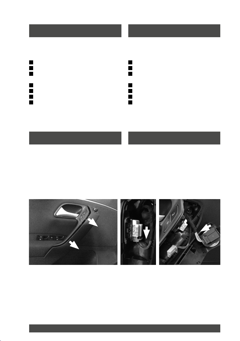
Entfernen Sie die Blende des Türgriffs. Setzen Sie hierzu einen Schraubenzieher o.ä.
an der Unterseite an und ziehen die Verkleidung vorsichtig zu sich.
Entriegeln Sie die Steckverbinder und ziehen Sie die Stecker heraus.
Carefully pry the grip dish out of the grip in
the door panelling use a slotted screwdriver
or similar tool. Pull the grip dish toward yourself. Be careful not to tilt the dish.
Unlatch the connectors and remove them.
Lösen Sie die darunter bendlichen
Torx-Schrauben sowie die Torxschrauben an
der unteren Türverkleidung sowie an der Seite(siehe Bild Folgeseite).
Loosen the screws wich are located behind
the grip dish and the torx screws at the doorpanel (shown in the next illustration on the
following side).
4
Page 5

Einbau der Lautsprecher Speaker installation
Das Foto zeigt die Positionen der Schrauben
und Klipse an. Pfeile kennzeichnen Schrauben, Kreise zeigen Klipse auf der Rückseite
der Türverkleidung auf.
The illustration shows the positions of the
screws and clips. Screws are displayed with
arrows, clips are displayed with circles, they
are behind the door panel.
SCREWS CLIPS
Hebeln Sie die Klipse von unten beginnend
vorsichtig ab. Dann die Türverkleidung vorsichtig nach oben aus dem Fensterschacht
heben.
Carefully pry the clips beginning at the bottom. Then pry the door panelling carefully out
of the window slot.
5
Page 6

Einbau der Lautsprecher Speaker installation
ACHTUNG!
Halten Sie die lose Türverkleidung entsprechend, dass keine Kabel auf Zug sind.
Greifen Sie anschließend hinter die Türverkleidung und lösen Sie den Seilzug der
Türinnenbetätigung. Hierfür die Lasche
anheben und den Zug nach hinten aus der
Führung ziehen. Anschließend den Haken
vorne am Kunststoffhebel aushängen. Lösen Sie die Stecker für Fensterheber und
ggf. Lautsprecher falls vorhanden und beachten Sie die Warn-LED der Alarmanlage
(Fahrerseite), diese sollten sie vorsichtig
den Stecker abziehen. Evtl. verbleibende
Clipse aus der Tür heraushebeln und wieder in die Türverkleidung einsetzen.
Einbau der Tieftonlautsprecher
Der Serienlautsprecher ist mit 4 Nieten befestigt. Bohren Sie diese vorsichtig mit einem
5 mm Bohrer und einer Bohrmaschine oder
einem Akku-Schrauber aus.
Entfernen Sie mit einem scharfen Seitenschneider o.ä. die Nietreste. Befestigen
Sie nun den neuen Lautsprecher mit den
beiliegenden Nieten. Verbinden Sie ide Steckkontakte wieder.
ATTENTION!
Be careful with the loosely door panel,
no cables should be under tension.
Loosen the door opening cable. Therefore
lift the ap and pull the cable backwards
out of the guide. Afterwards remove the
hook in front of the plastic lever. Loosen
the plugs for window regulator and if
necessary for loudspeakers. Please note
the warning LED (drivers side only), this
LED should be unplugged carefully before
removing the door panel. Pry possible remaining clips out of the door and re-insert
them into the door panelling.
Installation of the low-range speaker
The OEM-loudspeaker is fastened with 4 rivets. Drill the rivets carefully out by using a
5 mm drill bit and drill machine or cordless
screwdriver.
Carefully remove possible residue from the
door by using a sharp side cutter or something
else. Now fasten the new loudspeaker with
the included rivets. Plug all cables together.
6
Page 7

Einbau der Lautsprecher Speaker installation
Einbau der Hochtonlautsprecher Tweeter installation
Entfernen Sie die A-Säulenverkleidung indem
Sie diese mit einem geeignetem Werkzeug
vorsichtig abhebeln und ziehen Sie das Hochtönerkabel aus dem an der A-Säule befestigten Steckverbinder.
Carefully remove the A-pillar cover by using a
suitable tool and remove the tweeter cables
off the xed point at the A-pillar.
7
Page 8

Einbau der Lautsprecher Speaker installation
Entfernen Sie mit einem scharfen Messer die
drei Schmelzpunkte der Hochtönerfestigung.
Entfernen Sie das Schutzpapier des beigefügten Kleberings und setzen diesen auf den
neuen Hochtöner. Ziehen Sie anschließend
das Schutzpapier des Kleberingsab und stecken den Hochtonlautsprecher auf die Stifte
der Lautsprecheröffnung. Achten Sie darauf,
dass alle Klipse ordentlich eingerastet sind
und der Klebering ordnungsgemäß abdichtet.
Zur Sicherung verkleben Sie noch jeden der
drei Klipse mit handelsüblichem 2-Komponentenklebstoff.
Verbinden Sie die Steckkontakte.
Montieren Sie die A-Säulenverkleidung in umgekehrter Reihenfolge.
8
Cut with a sharp knife the three plastic welded
points and remove the original tweeter. Afterwards remove the protective paper from one
side of the included adhesive ring and place it
on the tweeter. After that, you can pull off the
other side of the adhesive ring, now you can
plug in the tweeter in the mounting area. Please note that every single clip is locked and the
adhesive ring caulks correctly.
For safety, glue each of the three clips with
normal commercial 2-component glue.
Reconnect all switch plugs.
Remount the A-pillar in reverse order.
Page 9

Einbau der Lautsprecher Speaker installation
Kontrollieren Sie alle Kabelsteckverbindungen und Clipse. Der Zusammenbau der Türpappen erfolgt in umgedrehter Reihenfolge.
Sollten Ihnen während der Demontage Klipse
abgebrochen sein, ersetzen Sie diese zuvor.
ACHTUNG!
Vergessen Sie nicht, alle Kabelsteckverbindungen wieder herzustellen und
den Seilzug der Türinnenbetätigung
korrekt einzuhängen.
Control each cable plug and every single clip.
The assembly of the doorboards had to be
done in reverse order. Change defect clips
before re-installing the doorboards.
ATTENTION!
Do not forget to reconnect all cable
plugs and to correctly replace the door
opening cable.
9
Page 10

Notizen Notes
10
Page 11

Technische Daten Technical data
· 2-Wege Front-System mit
Glas- / Papiermembrane
· 14,5 cm Tief- / Mitteltöner
· 25 mm Aluminiumhochtonkalotten
· Glasfaserverstärkter Polyamidkorb
· Inkl. Hochtonkabelfrequenzweichen
· Plug & Play zum einfachen Austausch
der Serienlautsprecher
· Musikbelastbarkeit: 80 W
· Impedanz: 2 Ohm
· Kennschalldruck 86,5 dB
· Resonanzfrequenz 1W: 69 Hz
· 2-way front-system with
glass- / papercone
· 14,5 cm bass- / midrange speaker
· 25 mm aluminum tweeter
· glass fibre reinforced polyamid baskets
· incl. tweeter x-overs
· plug & play for simple exchange of the
original loudspeakers
· music power: 80 W
· Impedance: 2 Ohm
· SPL 86,5 dB
· Resonance frequency 1W: 69 Hz
11
Page 12

ETON behält sich das Recht vor, die beschriebenen Produkte
ohne jegliche Vorankündigung zu verändern oder zu verbessern.
Alle Rechte sind vorbehalten. Die auch teilweise Vervielfältigung
des vorliegenden Handbuchs ist untersagt.
ETON reserves the rigth to make modications or improvements
to the products illustrated without notice thereof. All rights belong
to the respective owners.
Total or partial reproduction of this User‘s Guide is prohibited.
V 22.652
 Loading...