


ULTRACISION HARMONIC SCALPEL
ULTRACISION
®
HARMONIC SCALPEL
®
Service Manual

Chapter 1 - General Description
1.1 - The ULTRACISION HARMONIC SCALPEL System
Chapter 2 - Principles of Operation
2.1 - Hand Piece
2.2 - Generator and Foot Switch
Chapter 3 - Basic Operation
3.1 - Description of Controls, Indicators, and Connections
3.2 - Instrument Preparation and Hand Piece Attachment
3.3 - System Test
Chapter 4 - Initial Setup
4.1 - System Configuration
4.2 - Language Selection
4.3 - Line Rate Selection
Chapter 5 - Upper Level Diagnostics
5.1 - Trouble Shooting Guide
5.2 - Diagnostic Software
5.3 - Extended Functional Test
Chapter 6 - Detailed Diagnostics
6.1 - Test Equipment
6.2 - Hand Piece Assembly
6.3 - Generator and Foot Switch
6.3.1 - Power Entry Module
6.3.2 - AC Fusing and Distribution
6.3.3 - Compressor
6.3.4 - Low Voltage Transformer
6.3.5 - High Voltage Transformer
6.3.6 - Generator PCB
6.3.7 - Keyboard/Interlock PCB
6.3.8 - Microprocessor PCB
6.3.9 - Liquid Crystal Display
6.3.10 - Foot Switch
Chapter 7 - Specifications
7.1 -Generator
7.2 - Hand Piece
7.3 - Foot Switch
7.4 - Power Cord
7.5 - Transport and Storage
7.6 - Mode of Operation
3
3
6
9
9
16
27
ULTRACISION
®
HARMONIC SCALPEL
®
Service Manual
Table of Contents

ULTRACISION
®
HARMONIC SCALPEL
®
Service Manual
Table of Contents - continued
Appendix A - Diagnostic Service Mode - Flow Diagram
Appendix B - Wiring Diagrams and Schematic
115 Volt Wir ing (Model GEN01)
230 Volt Wiring (Models GEN22, GEN32)
115 Volt Routing (Model GEN01)
230 Volt Routing (Models GEN22, GEN32)
Generator PCB Schematic
Generator PCB Component Location
Keyboard/Interlock PCB Schematic
Keyboard/Interlock Component Location
CPU PCB Schematic
CPU PCB Component Location
Type CF, Isolated Applied Part Dangerous Voltage

2.1
Hand Piece
1.1
The
ULTRACISION
System
2.2
Generator and
Foot Switch
Chapter 1 - General Description
3
The ULTRACISION HARMONIC SCALPEL System is indicated for incising tissue when bleeding control and minimal
thermal injury are desired. The System’s instruments can be used as an adjunct to or substitute for electrosurgery and
steel scalpels. The System operates in two power modes, variable and full.
The ULTRACISION HARMONIC SCALPEL instrument blades vibrate longitudinally at 55 kilohertz. This ultrasonic
vibration at the blade enhances its cutting ability while the vibrating blade edge coagulates bleeders as tissues are
incised. Hemostasis occurs when tissue couples with the blade. This coupling causes collagen molecules within the
tissue to vibrate and become denatured, forming a coagulum.
The cutting power can be adjusted during the incision to increase or decrease coagulation and speed of cutting.
Coagulation of large bleeders can be accomplished by captive coagulation where the side of the blade is used to
compress and tamponade the vessel while a short duration of full power seals it.
Chapter 2 - Principles of Operation
The System consists of three major components, a Generator, a Hand Piece, and a Foot Switch. The Generator
produces a 55 kilohertz electric signal which is transmitted via a coaxial cable to the Hand Piece, which then
converts the electrical signal into ultrasonic, mechanical motion. A more detailed explanation follows.
The Hand Piece houses three major components that generate, amplify, and deliver ultrasonic energy to tissues.
When each component is attached to the other and tuned to 55 kilohertz, an acoustic drive train is formed. The
acoustic system or acoustic drive train consists of three components:
• Acoustic Transducer: converts the electrical energy into motion. The transducer consists of four piezoelectric
elements held in compression between two aluminum end bells. When an AC wave form is applied to the
transducer, the ceramics expand and contract to produce longitudinal motion.
• Acoustic Mount: attaches the acoustic drive train to the Hand Piece. The mount also provides mechanical
amplification of the longitudinal motion.
• Instrument Blade: couples the ultrasonic energy to the tissue and amplifies motion. In a laparoscopic
configuration, the blade is elongated by means of a "Laparosonic Extension." This extension allows the
ultrasonic energy to propagate from the Hand Piece to the instrument blade with minimal loss.
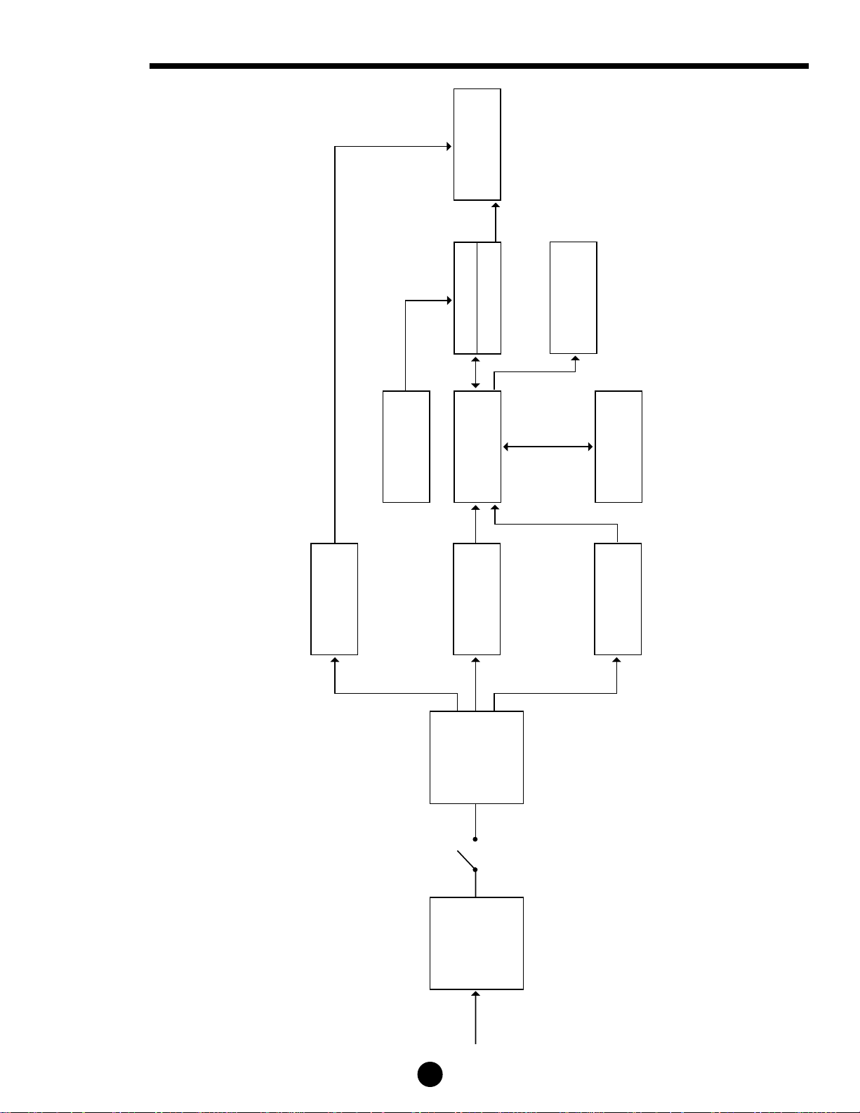
The Generator consists of ten modules that drive and cool* the Hand Piece. The Generator converts the AC line
voltage to a controlled DC level. The DC level is then remodulated at the resonant frequency of the Hand Piece. The
remodulated signal is then filtered and delivered to the Hand Piece where it resonates the acoustic train. A more
detailed description follows.
• Power Entry Filter: accepts a standard, hospital grade utility cord. It provides susceptibility filtering from the
external environment as well as suppressing electromagnetic emissions produced by the Generator that could be
conducted back through the power cord.
• AC Fusing and Distribution Components: provide line voltage to a cooling compressor, a high voltage
transformer, and a low voltage transformer. Fusing protects these assemblies and others from overload
conditions.
• Cooling Compressor: provides cooling air via a silicone hose to Hand Piece models HP050, HP051, HPTUV,
and H1TUV.
* Generator provides cooling to models HP050, HP051, HPTUV and H1TUV only.

• Low Voltage Transformer: produces low voltage AC that is later rectified, filtered, and regulated to produce
+5 VDC, +12 VDC, and -12 VDC. It also provides an important safety barrier. The voltage generated on the
secondary of the transformer is isolated - i.e. the voltage is not referenced to earth ground.
• High Voltage Transformer: produces high voltage AC (250 VAC) that is later rectified, filtered and regulated
to produce a variable DC level used in driving the Hand Piece. It also provides an important safety barrier. The
voltage generated on the secondary of the transformer is isolated - i.e. the voltage is not referenced to
earth ground.
• Generator PCB: produces power at ultrasonic frequencies to drive the Hand Piece. This is accomplished
as follows:
- An SCR switching circuit, filter, and software regulate power rectified from the high voltage transformer
to a predefined level, determined by the user-selected power level. Additionally, a zero crossing detection
circuit informs the software when the AC line voltage swings through zero volts. This allows the software
to schedule SCR firings.
- The DC voltage is then converted into a 55 kilohertz (+/-2 KHz) square wave by means of a
FET switching circuit.
- The 55 kilohertz square wave is then filtered by a resonant LC network to produce the sinusoidal wave
form that drives the hand piece.
In addition, the generator PCB contains a phase lock loop circuit that monitors the resonant frequency of
the Hand Piece and adjusts the 55 kilohertz up or down to stay at resonance, which changes with
temperature and load.
A secondary function of the Generator PCB is to provide a central point of connectivity for the other PCBs and
modules in the Generator.
The third function is to rectify, filter, and regulate the low voltage AC to generate the logic voltages. These
voltages are +5 VDC, +12 VDC, and -12 VDC. Logic voltage is also inverted to supply power for the
LCD back light.
• Keyboard/Interlock PCB: The Keyboard portion of this PCB informs the user of the operative state of the
ULTRACISION HARMONIC SCALPEL System using LED indicators. It also allows the user to change the default
settings as described in Chapter 3 of this manual and in the Generator Manual.
The interlock portion of this assembly acts as a shunt, placing a resistive load across the output to the blade
whenever it is not activated at the VAR or FULL power levels. The interlock is used to quickly stop the blade
motion once the Foot Switch pedal is released.
• Microprocessor PCB: The microprocessor PCB contains the software program that drives the ULTRACISION
HARMONIC SCALPEL System. The software monitors zero crossings, regulates DC voltage, processes button
and pedal activations, and drives the liquid crystal display. It also monitors performance of the generator PCB
and the acoustic drive train.
• Liquid Crystal Display: The liquid crystal display reports the operative mode of the ULTRACISION System.
It is driven by the microprocessor PCB via the generator PCB.
• Foot Switch: The Foot Switch module allows the user to activate the system in either variable or full mode
based on which foot pedal is being pressed. Pedal activations are communicated with the microprocessor via the
keyboard/interlock and generator PCB.
4
2.2
Generator and
Foot Switch
continued
Chapter 2 - Principles of Operation continued
Chapter 2 - Principles of Operation continued
5
POWER
ENTRY
MODULE/
FILTER
FUSING &
AC
DISTRIBUTION
HIGH VOLTAGE
TRANSFORMER
MICROPROCESSOR
PCB
GENERATOR
PCB
COMPRESSOR
AIR (models HP050, HP051, HPTUV & H1TUV)
KEYBOARD
INTERLOCK
FOOT-
SWITCH
HAND PIECE
55 KHz
AC
LCD
LOW VOLTAGE
TRANSFORMER
Generator
System Overview
6
Chapter 3 - Basic Operation
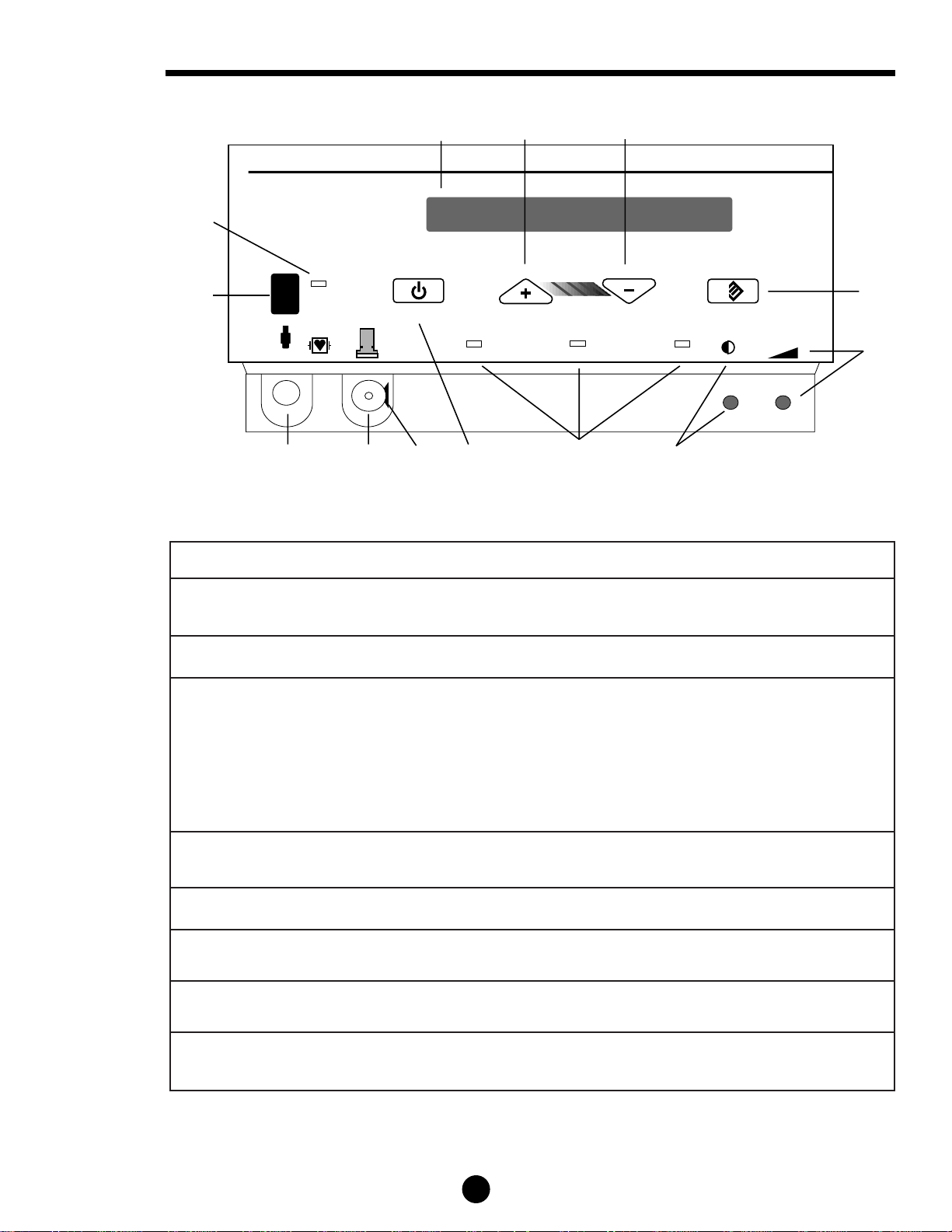
3.1
Controls,
Indicators, and
Connections
STANDBY
SAVE
FULL VARIABLE READY
GENERATOR
ETHICON ENDO-SURGERY
5432
1
ULTRACISION
1
2
3
4
5
6
7
10
11
12
9
8
13
Note: This illustration shows Generator Model GEN01. In Model GEN32, the position of the air and electrical connectors is reversed.
Component Description
1 Power Switch Controls the electrical power for the entire Generator. Push the switch up to turn power on, push
the switch down to turn power off.
2 Green Power Indicator Light The light is illuminated when the Generator power is on.
3 20 Character Liquid Crystal In READY mode, this display indicates the selected variable power level. When the Hand Piece
Display is energized, this display indicates the active power level. “STANDBY” is displayed
when the Generator is in STANDBY mode.
When the Generator power is first turned on, this display briefly indicates that a SELF TEST is in
progress. This display is also used for alarm messages.
When activated by service personnel, this display also shows diagnostic information, language
selection, and Generator adjustment information.
4 Increase Power Button Push this button to increase the variable power setting to the desired level, as displayed on the
liquid crystal display, from 1 (minimum power) to 5 (maximum power).
5 Decrease Power Button Push this button to decrease the variable power setting to the desired level from 5 to 1.
6 Save Button Push this button to save the currently selected variable power level so that it is automatically
displayed the next time the Generator power is turned on.
7 Volume Turn this knob to adjust the sound of the Audio Annunciator. The sound level cannot be adjusted
to zero.
8 Display Turn this knob to obtain the best liquid crystal display appearance for your particular lighting and
viewing angle.

7
Chapter 3 - Basic Operation continued
3.1
Controls,
Indicators, and
Connections
continued
3.2
Instrument
Preparation and
Hand Piece
Attachment
9 Status Lights Ready Light. This light is illuminated when the system is ready to use. This light is off while the
Hand Piece is energized or in STANDBY mode.
Variable Light. This light is flashed on and off when the Hand Piece is energized at the
variable (VAR) power level.
Full Light. This light is flashed on and off when the Hand Piece is energized at the full
(FULL) power level.
10 Standby Button This button toggles between STANDBY and READY mode. Push this button once to enter
STANDBY mode. In STANDBY mode, all power is removed from the Hand Piece. The Increase,
Decrease, and Save buttons are disabled as is the Foot Switch. Use the STANDBY mode when
replacing instrument blades.
11 Release Button Push this button to detach the Hand Piece cord connection from the Cooling Air Source
Connector on the Generator.
12 Cooling Air Source Refer to the appropriate Hand Piece package insert.
13 Electrical Receptacle Delivers the energy from the Generator to the Hand Piece.
* Audio Annunciator The annunciator beeps to indicate instrument activity or to indicate error conditions. During
normal activation, the annunciator beeps on and off when either foot pedal is pressed. A slower
beep indicates that LEVEL 1 through LEVEL 4 is activated and a faster beep indicates that
LEVEL 5 is activated. If the generator does not energize the instrument, the annunciator will emit
a continuous beep when either pedal is pressed.
Instrument Preparation and Hand Piece Attachment
Step Instruction
1 Ensure that the Generator Power Switch is off during instrument preparation.
WARNING: To avoid injury, the activatedULTRACISION HARMONIC SCALPEL
instrument should not be in contact with drapes or other flammable materials. During
prolonged activation, the instrument blades may become hot. Avoid unintended blade
contact with tissue, drapes, surgical gowns, or other unintended sites after activation.
2 Plug the line cord into a grounded receptacle:
Model GEN01: 115 Vac, 60 Hz
Model GEN32: 230 Vac, 50 Hz
Note: Do Not Connect the Generator To An Ungrounded Outlet.
3 Connect the Foot Switch to the rear panel of the Generator. Align the red dot on the Foot
Switch 4-pin connector with the red dot 4-pin connector on the lower left side of the
Generator back panel.

3.3
System Test
8
3.2
Instrument
Preparation and
Hand Piece
Attachment
continued
Chapter 3 - Basic Operation continued
4 Attach the sterile ULTRACISION
®
HARMONIC SCALPEL
®
Hand Piece following the
appropriate package insert instructions:
Note: Refer to specific instrument package inserts for use of the Generator during surgical cases.
5 Attach an instrument blade to the Hand Piece following the instructions listed in the
instrument’s package insert.
6 Turn Generator power on.
7 If the Hand Piece has been steam sterilized (autoclave or flash), wait 5 minutes with the
Hand Piece attached to the Generator and the Generator on to allow the Hand Piece to dry.
STANDBY Mode is recommended during this period of time.
8 If the Generator is in STANDBY Mode, press the Standby Button to return it to READY
Mode. If the generator is not already at power level 5, select level 5 by using the Increase
Button.
Step Instruction
1 Energize the blade by pressing a pedal on the Foot Switch.
2 Apply the blade to wood, cardboard, or wax and verify the blade burns and cuts. If the
system fails this basic functional verification, refer to the upper level diagnostic section of
this manual (Chapter 5).
The ULTRACISION HARMONIC SCALPEL System is now ready for testing. After performing the very basic
tests which follow, the more detailed functional tests described in section 5.3 are recommended.
Caution: During this testing, the instrument blade will become active. Do not touch the blade!

9
Two features of the system are user programmable. They are the displayed language and line rate.
The system may be configured to display messages in languages other than the default setting of English. These
languages are French, Spanish, Italian, and German. Also, the system can be configured to run at 50 or 60 Hertz.
The system is preset at the factory such that all 115 VAC units (Model GEN01) are at 60 Hz, and all 230 VAC
units (Model GEN32) are at 50 Hz. If the line rate is set inappropriately, a system error will always be displayed at
normal power up. To change the language or line rate, refer to the following sections.
Follow steps 1 through 5 in section 3.2 to prepare the Generator for power up. Prior to turning the Generator on,
press and hold the Increase and Decrease Buttons simultaneously with one hand. While holding these two buttons
in, turn the Generator power on. Once the power light comes on, release the two buttons. The preset language and
software revision (1.35) should now be displayed. This indicates that the first page of the service mode is accessed.
If you are unable to access this first page of the service mode, refer to section 5.2.
In the first page of the service mode, different languages can be displayed by pressing the Increase Button. Once
the desired language is located, press the Save Button and turn the Generator off. All display messages will now be
in the newly selected language.
Enter the first page of the service mode as described above. Press the Standby Button to access the second page of
the service mode. In this second page, the display will indicate the line rate currently selected. The line rate may be
toggled between 50 Hz and 60 Hz by pressing the Increase Button.
A validation sequence is required to change the line rate. In addition to updating the line rate, the memory check
sum is updated and the error history is erased. This is explained in more detail in section 5.2. Before entering the
validation sequence, verify that the number following the letters CRC is 55947. If this is not the case, do not
continue with the validation (see section 5.2). Once 55947 is verified, enter Save, Increase, Decrease, Save, and
Standby sequentially. The Generator is now configured to operate at the selected line rate
Chapter 5 - Upper Level Diagnostics
This section discusses the most common problem areas and how to resolve these problems primarily through
modifications to usage and swapping of blades and hand pieces. This section is a good place to start once a
problem has been identified.
The testing sequence should proceed as follows:
1. Perform the basic functional test as described in section 3.3.
2. Starting with section 5.1 (Trouble Shooting Guide), work through the sub-sections (5.2 and 5.3) until
the problem is identified.
3. If the problem then is still unidentified, refer to Chapter 6 for a module by module diagnosis.
The following section lists the probable causes and corrective actions for error conditions that may occur during
operation of the ULTRACISION HARMONIC SCALPEL Generator. If the symptoms specified in this section are
inappropriate or the corrective actions are insufficient, consult a qualified hospital technician or call one of the
following numbers for service:
• 1-800-USE-ENDO (U.S. calls)
• 1-513-483-8901 (International calls - English speaking only)
4.2
Language
Selection
4.1
System
Configuration
4.3
Line Rate
Selection
Chapter 4 - Initial Setup
5.1
Trouble
Shooting Guide
 Loading...