


 *
*
Generator 300 System
Service Manual
*Formerly known as UltraCision ® Harmonic Scalpel®
Harmonic, UltraCision and Harmonc Scalpel are tradmarks of Ethicon Endo-Surgery.
Go to www.e-ifu.com for the latest version of this manual. |
GEN04 |

Table of Contents
Introduction – Harmonic Generator 300 System . . . |
. . . |
. |
. . . |
. . . . . |
. . . |
. |
. |
. |
3 |
|
Scope |
. . . . . . . . . . . . . . . . . . . . . . . |
. . . . . |
. . |
. . . . . |
. . . . . . . . . |
. . . . . |
. . |
. . |
. |
. 3. . . . . . . . . . . . . . |
Installation Guidelines . . . . . . . . . . . . . . . . . . . |
. . . . . . |
. . . |
. . . . . . |
. . . . . . . . . . . |
. . . . . . . |
. . |
. . . |
. |
3 |
|
Product Information . . . . . . . . . . . . . . . . . . . . . |
. . . . . . |
. . . |
. . . . . . |
. . . . . . . . . . . . |
. . . . . . |
. . . |
. . |
. |
3 |
|
Service . . . . . . . . . . . . . . . . . . . . . . . |
. . . . . |
. . |
. . . . . |
. . . . . . . . . |
. . . . . |
. . |
. . |
. |
. 3. . . . . . . . . . . . . . |
|
Chapter 1 – Warnings, Precautions and Notes . . . . . . . . . . . . . . . . . . . . . 5
Warnings and Precautions . . . . . . . . . . . . . . . . . . . . . . . . . . . . . . . . . . . . . . . . . . . . . . . . . . . . . . . 5 Notes. . . . . . . . . . . . . . . . . . . . . . . . . . . . . . . . . . . . . . . . . . . . . . . . . . . . . . . . . . . . . . . . . . . . . . . . 6
Chapter 2 – General Description . . . . . . . . . . . . . . . . . . . . . . . . . . . 7
System Description . . . . . . . . . . . . . . . . . . . . . . . . . . . . . . . . . . . . . . . . . . . . . . . . . . . . . . . . . . . . . 7 Indications . . . . . . . . . . . . . . . . . . . . . . . . . . . . . . . . . . . . . . . . . . . . . . . . . . . . . . . . . . . . . . . . . . . . 7 Contraindications .. .. .. .. .. .. .. .. .. .. .. .. .. .. .. .. .. .. .. .. .. .. .. .. .. .. .. .. .. .. .. .. .. .. .. .. .. .. .. .. .. .. .. .. .. .. .. .. .. .. .. .. .. .. .. .. .. .. .. .. .. .. .. 7 System Components . . . . . . . . . . . . . . . . . . . . . . . . . . . . . . . . . . . . . . . . . . . . . . . . . . . . . . . . . . . . 7 Power Levels . . . . . . . . . . . . . . . . . . . . . . . . . . . . . . . . . . . . . . . . . . . . . . . . . . . . . . . . . . . . . . . . . . 7
Chapter 3 – Theory of Operation . . . . . . . . . . . . . . . . . . . . . . . . . . . 9
Chapter 4 – System Setup . . . . . . . . . . . . . . . . . . . . . . . . . . . . . 11
Unpacking Instructions . . . . . . . . . . . . . . . . . . . . . . . . . . . . . . . . . . . . . . . . . . . . . . . . . . . . . . . . . 11 Initial Setup . . . . . . . . . . . . . . . . . . . . . . . . . . . . . . . . . . . . . . . . . . . . . . . . . . . . . . . . . . . . . . . . . . 11
Chapter 5 – Operation 15 |
|
Controls, Indicators, and Connections . . . . . . . . . . . . . . . . . . . . . . . . . . . . . . . . . . . . . . . . . |
15. . . |
Screen Descriptions .. .. .. .. .. .. .. .. .. .. .. .. .. .. .. .. .. .. .. .. .. .. .. .. .. .. .. .. .. .. .. .. .. .. .. .. .. .. .. .. .. .. .. .. .. .. .. .. .. .. .. .. .. .. .. .. .. .. .. |
17 |
System Operation . . . . . . . . . . . . . . . . . . . . . . . . . . . . . . . . . . . . . . . . . . . . . . . . . . . . . . . . . . . . . |
19 |
System Shutdown . . . . . . . . . . . . . . . . . . . . . . . . . . . . . . . . . . . . . . . . . . . . . . . . . . . . . . . . . . . . . |
20 |
Chapter 6 – Cleaning and Disinfection . . . . . . . . . . . . . . . |
. . . . . . . . . . . . . . . . . . . . . . . . . . . . . . . . .21. . . . . . |
Generator and Cart Cleaning . . . . . . . . . . |
. . . . . . . . . . . . . . . . . . . . . . . . . . . .21. . . . . . . . . . . . . |
Foot Switch Cleaning . . . . . . . . . . . . . . . . . . . . |
. . . . . . . . . . . . . . . . . . . . . . . . . . . . . . . . . . .21. . . |
Disinfection (Generator, Footswitch and Cart) |
. . . . . . . . . . . . . . . . . . . . . . . . . . . . . . . 21. . . . . . . |
Chapter 7 – Safety and Function Testing |
. . . . . . . . . . . . . . . . . . . . . . . 23 |
Safety Test . . . . . . . . . . . . . . . . . |
. . . . . . . . . . . . . . . . . . . . . . . . . . . . . . . . . . . . . . . . . . . . . . . . . . 23 |
Function Test . . . . . . . . . . . |
. . . . . . . . . . . . . . . . . . . . . . . . . . . . . . . . . . . . . . . . . . .23. . . . . . . . . . |
Chapter 8 – Generator Output Check . . . . . . . . . . . . . . . . . . . . . . . . 25
Procedure for Checking the Output of GEN300 Generators . . . . . . . . . . . . . . . . . . . . . . . . . . 25
Chapter 9 – High-Level System Troubleshooting . . . . . . . . . . . . . . . . . . . . . . . . . . . . . . . . . . . 27. . . . . . . . .
Audible Indicators and Alarms . . . . . . . . . . . . . . . . . . . . . . . . . . . . . . . . . . . . . . . . . . . . . . . . . . . 27 Error Codes and Displays in Normal Operating Mode . . . . . . . . . . . . . . . . . . . . . . . . . . . . .28. .
Chapter 10 – Hand Piece Checkout . . . . . . . . . . . . . . . . . . . . . . . . . 37
Procedure for Checkout/Screening of HP054 Hand Pieces . . . . . . . . . . . . . . . . . . . . . . . . . . . . 37
GEN04 |
Go to www.e-ifu.com for the latest version of this manual. |
1 |

Service Manual
Chapter 11 – Advanced Error Codes . . |
. . . . . . . . . . . . . . . . . . . . |
. |
. |
. |
39 |
Error Code Display . . . . . . |
. . . . . . . . . . . . . . . . . . . . . . . . . . . . . . . . . |
. . |
. |
. . |
.39. . . . . . . . . . . . . . |
Error Codes . . . . . . . . . . . . . |
. . . . . . . . . . . . . . . . . . . . . . . . . . . . . . . . . . . . . . . . . |
. . |
. |
. . . |
39. . . . . |
Software Version . . . . . . . |
. . . . . . . . . . . . . . . . . . . . . . . . . . . . . . . . . . |
. . |
. |
. . |
. 40. . . . . . . . . . . . . . |
Estimating Hand Piece Usage |
. . . . . . . . . . . . . . . . . . . . . . . . . . . . . . . . . . . |
. . |
. |
. . . 40. . . . . . . . . . |
|
Generator Error Log Record |
. . . . . . . . . . . . . . . . . . . . . . . . . . . . . . . . . . . . . . . . . . . . . |
. . |
. |
. . . |
41 |
Hand Piece Error Log Record |
. . . . . . . . . . . . . . . . . . . . . . . . . . . . . . . . |
. . |
. |
. . |
.41. . . . . . . . . . . . |
Chapter 12 – Hardware Troubleshooting . . . . . . . . . . . . . . . . . . . . . . . |
|
43 |
|
|
Common Failures . . . . . . . . . . . . . . . . . . . . . . . . . . . . . . . . . . . . . . . . . . . . . . . . . . . . . . . . . . . |
. |
. 45 |
|
Procedures . . . . . . . . . . . . . . . . . . . . . . . . . . . . . . . . . . . . . . . . . . . . . . . . . . . . . . . |
. |
. 47. . . . . . . . . |
Chapter 13 – |
Generator Calibration . . . . . . . . . . . . . . . . . . . . . . . . . |
|
57 |
|
Required Schedule . . . . . . . . . . . . . . . . . . . . . . . . . . . . . . . . . . . . . . . . . . . . . . |
. |
. 57. . . . . . . . . . . . |
|
Calibration Procedures . . . . . . . . . . . . . . . . . . . . . . . . . . . . . . . . . . . . . . . . . . . . . . . . . . . . . . . |
. |
. 57 |
|
Calibration One . . . . . . . . . . . . . . . . . . . . . . . . . . . . . . . . . . . . . . . . . . . . . . . . . . . . . . . . . |
. |
. 57 |
|
Calibration Two . . . . . . . . . . . . . . . . . . . . . . . . . . . . . . . . . . . . . . . . . . . . . . . . . . . . . . . . . |
. . |
59 |
Chapter 14 – System Specifications . . . . . . . . . . . . . . . . . . . . . . . . . |
|
61 |
|
Chapter 15 – |
Adjustments . . . . . . . . . . . . . . . . . . . . . . . . . . . . . |
|
65 |
|
Power Level Adjustment . . . . . . . . . . . . . . . . . . . . . . . . . . . . . . . . . . . . . . . . . . |
. |
. .65. . . . . . . . . . |
|
Audible Activation Tone Adjustment . . . . . . . . . . . . . . . . . . . . . . . . . . . . . . . |
. |
.65. . . . . . . . . . . . |
Chapter 16 – Service and Repair . . . . . . . . . . . . . . . . . . . . . . . . . . . . . . . . . . . . . . . . |
. |
. 67. . . . . . . . . . . . . . . . . |
|
|
Repair Strategy .. .. .. .. .. .. .. .. .. .. .. .. .. .. .. .. .. .. .. .. .. .. .. .. .. .. .. .. .. .. .. .. .. .. .. .. .. .. .. .. .. .. .. .. .. .. .. .. .. .. .. .. .. .. .. .. .. .. .. .. .. |
.. .. |
67 |
|
Available Resources . . . . . . . . . . . . . . . . . . . . . . . . . . . . . . . . . . . . . . . . . . . . . . . . . |
. |
.67. . . . . . . . |
|
Service and Repair Returns . . . . . . . . . . . . . . . . . . . . . . . . . . . . . . . . . . . . . . . . . . |
. |
. 67. . . . . . . . . |
Chapter 17 – Warranty . . . . . . . . . . . . . . . . . . . . . . . . . . . . . . . . . . . . . . . . . . . . . . . . . . . . . . . . . . . . . . . . . . . |
. |
69 |
|
Chapter 18 – Symbols . . . . . . . . . . . . . . . . . . . . . . . . . . . . . . . . . . . . . . . . . . . . . . . . . . . . . . 71. . . . . . . . . . . . . . |
|||
Appendix A – |
Mains Power Wiring Diagram . . . . . . . . . . . . . . . . . . . . . |
. |
73 |
Appendix B – |
GEN04 Assembly Diagram . . . . . . . . . . . . . . . . . . . . . . . |
|
75 |
Appendix C – |
GEN04 Top Level Diagram . . . . . . . . . . . . . . . . . . . . . . |
. |
77 |
Appendix D – Procedure for Upgrading from Software 1.09 to Software 1.20 . . . . . . . |
. |
79 |
|
2 |
Go to www.e-ifu.com for the latest version of this manual. |
GEN04 |

Introduction
Scope
This manual and the equipment it describes are for use only by qualified Biomedical Service Personnel. It is intended only as a guide for technical maintenance of the Harmonic® Generator 300 System.
This manual is intended to be a companion to the Harmonic Generator 300 System User Manual. A thorough understanding of the User Manual is required to properly understand and use the information in this service manual.
Installation Guidelines
The person installing the device shall ensure that the installation, inspection, and any required testing are performed in accordance with the instructions in this and the Harmonic Generator 300 System User Manual. The inspection shall be documented along with any test results to demonstrate proper installation.
Ethicon Endo-Surgery reserves the right to change the electrical/electronic or mechanical configurations and components without notice. Schematic revisions may not match PCB revisions in the unit being maintained; consult Ethicon Endo-Surgery before making any changes. When necessary, amendments to this manual will be made available by request only.
Product Information
Product Name: Harmonic Generator 300 System (formerly known as UltraCision® Harmonic Scalpel® Generator 300 System)
Model Number/Product Code: GEN300/GEN04
Voltage: 100 – 240 VAC
This manual is subject to revision. When referring to this manual please include the following:
Document Type: Service Manual
Document Number: P40401P0X (on back cover of manual)
Manufactured by:
Ethicon Endo-Surgery, LLC Guaynabo, Puerto Rico 00969 USA 1-800-USE-ENDO (U.S.Customers) http://www.harmonicscalpel.com
Service
1-800-USE-ENDO (U.S. Customers)
Customers outside the U.S. should contact their Ethicon Endo-Surgery representative for assistance.
GEN04 |
Go to www.e-ifu.com for the latest version of this manual. |
3 |

Service Manual
4 |
Go to www.e-ifu.com for the latest version of this manual. |
GEN04 |

Chapter 1 - Warnings, Precautions and Notes
•This equipment, in conjunction with the accessories, is intended to produce high-frequency mechanical energy which enables hemostatic cutting and/or coagulation of soft tissue.
•Safe and effective ultrasonic surgery is dependent not only upon equipment design, but also, to a large extent, upon factors under control of the user. It is important that the instructions supplied with this equipment be read, understood, and followed in order to enhance safety and effectiveness.
•The Harmonic Generator 300 System, including the hand piece, is not Magnetic Resonance safe and is not Magnetic Resonance compatible.
•Equipment is not suitable for use in the presence of a flammable anesthetic mixture with air or with oxygen or nitrous oxide. It is possible to create sparks by hitting other metal instruments. Sparks may ignite flammable gases such as bowel gas.
•The Harmonic Generator 300 System must be operated within the required ambient operating conditions. Refer to Chapter 14 – System Specifications.
•The Harmonic Generator 300 System should be tested on a periodic basis by qualified biomedical maintenance personnel to ensure proper and safe operation.
•Refer all servicing to qualified biomedical personnel. Your Ethicon Endo-Surgery representatives are available to assist in having your equipment serviced.
•Removing the top cover of the generator unit may expose the user to parts within the generator unit which may have high surface temperatures and high voltage. These surfaces are potentially dangerous and should be treated with extreme caution.
•Always unplug the generator from the wall outlet prior to opening the cover for servicing. This poses a potential electric shock hazard.
•After removing the cover, inspect the internal components for obvious damage or foreign debris.
Never power ON a suspected problem unit.
•Never remove or install any parts with power on.
•The active blade of a Harmonic instrument heats the tissue by friction and is intended to supply sufficient friction and shearing effect to cut and coagulate tissue in contact with the active blade. As a result, the user should use caution with the blade, clamp arm, and distal part of the shaft as they may exhibit an elevated temperature. Additional temperature information may be contained in individual instrument instructions for use.
•The user should verify that the power receptacle with which this unit is used is properly grounded and is correctly polarized. Do not use ground cheater plugs or extension cords. Do not connect the Harmonic Generator 300 System to an ungrounded outlet. Grounding reliability can only be achieved when this equipment is connected to a hospital-grade receptacle. (Refer to
Chapter 14 – System Specifications.)
•Verify that the outlet voltage correctly corresponds to the generator’s requirements. (Refer to
Chapter 14 – System Specifications.) Connection to an improper power supply may result in damage to the generator and risk of shock or fire hazard.
GEN04 |
Go to www.e-ifu.com for the latest version of this manual. |
5 |

Service Manual
•Do not connect the Harmonic Generator 300 System to an ungrounded outlet. Grounding reliability can only be achieved when this equipment is connected to a hospital-grade receptacle.
•Spilling or spraying fluids on or into the generator or immersing the generator may result in damage to the generator and risk of shock or fire hazard.
•Do not place liquid containers on top of the unit. Wipe spilled liquids off the unit immediately. To avoid inadvertent penetration of liquids, do not operate this unit in a tilted position.
•Locate the Harmonic Generator 300 System, including the hand piece cable, at least 3 ft. (approximately 1 m) from electrosurgical systems and their hand piece (e.g., pencil) cables. The generator should not be on the same circuit as other equipment and machines. Please note that different outlets may not necessarily mean different circuits.
•To prevent overheating during use, ensure that the air vents found on the generator’s bottom and back panels are not blocked and that they allow adequate clearance from obstructions to allow air to flow freely through the generator enclosure. Avoid placing the generator on a soft surface.
•Use proper electrical safety and hospital procedures when working on the generator unit.
•The AC mains voltage presents a shock hazard and is accessible when the generator cover is removed.
Caution must be used near internal system components, which attach directly to the AC mains such as the power entry module, mains fuses, power switch, and open-frame 48V power supply.
•It is hazardous to connect non-isolated probes to specific isolated sections of the generator. Doing so may introduce a high voltage from the hand piece to earth ground and produce a shock hazard.
•Refer to all other Harmonic System documentation to review operating procedures.
Notes
•Use only Ethicon Endo-Surgery approved replacement parts. Contact the Ethicon Endo-Surgery representative for assistance in obtaining replacement parts by calling 1-800-USE-ENDO for customers in the United States. Customers outside the U.S. should contact their Ethicon Endo-Surgery representative for assistance.
•Minimizing operating temperature and extreme thermal cycles will extend the life of the equipment.
•Throughout this manual “instrument(s)” refers to the Harmonic Generator 300 System blades, ball coagulators, or coagulating shears.
6 |
Go to www.e-ifu.com for the latest version of this manual. |
GEN04 |

Chapter 2 - General Description
System Description
The Harmonic Generator 300 System utilizes ultrasonic energy to enable hemostatic cutting and/or coagulation of soft tissue. The system consists of an ultrasonic generator, a foot switch, an optional hand switching adaptor, a hand piece, and a variety of open and minimally invasive instruments.
Note: Throughout this manual “instrument(s)” refers to the Harmonic Generator 300 System blades, ball coagulators, or coagulating shears.
The Harmonic instruments vibrate longitudinally at 55.5 kilohertz. This ultrasonic vibration at the blade enhances its cutting ability. The same vibration seals small vessels with coagulated blood and tissue proteins. Hemostasis occurs when tissue couples with the instrument. This coupling causes collagen molecules within the tissue to vibrate and become denatured, forming a coagulum.
Note: Refer to package inserts provided separately for information about the Hand Piece, Hand Switching Adaptor, Test Tip and Instruments prior to using the system.
Indications
The Harmonic Generator 300 System is indicated for soft tissue incisions when bleeding control and minimal thermal injury are desired. The Harmonic Generator 300 System instruments can be used as an adjunct to or substitute for electrosurgery, lasers, and steel scalpels.
Contraindications
•The instruments are not indicated for incising bone.
•The instruments are not intended for contraceptive tubal occlusion.
System Components
Generator 300
The generator supplies the hand piece with electrical energy and facilitates selection of power levels, system monitoring, and system diagnostics.
Power is delivered by activating the foot switch or hand switching adaptor.
Hand Piece
The hand piece contains an acoustic transducer that converts the electrical energy supplied by the generator to mechanical motion. The transducer is connected to an ultrasonic wave guide/amplifier which amplifies the motion produced by the transducer and relays it to the instrument.
Instrument
The mechanical motion from the hand piece advances to the instrument, transmitting ultrasonic energy which enables hemostatic cutting and/or coagulation of tissue.
Power Levels
The generator delivers two power levels: minimum (MIN) and maximum (MAX). The minimum power level may be adjusted by the user from Level 1 to 5. The maximum power level is always Level 5. With all instruments except the ball coagulator, use a higher generator power level for greater tissue cutting speed and a lower generator power level for greater coagulation. For the ball coagulator, higher generator power levels will provide greater coagulation. The amount of energy delivered to the tissue and resultant tissue effects are a function of many factors including the power level selected, instrument characteristics, grip force (when applicable), tissue tension, tissue type, pathology, and surgical technique.
Note: Refer to the instruments’ package inserts for additional power level information.
GEN04 |
Go to www.e-ifu.com for the latest version of this manual. |
7 |

Service Manual
8 |
Go to www.e-ifu.com for the latest version of this manual. |
GEN04 |
Chapter 3 - Theory of Operation
The Harmonic Generator 300 System consists of the following components: Generator (GEN04),
hand piece, instruments, foot switch, and hand switching adaptor (if used). The generator produces an electric signal, which is transmitted via a coaxial cable to the hand piece, which then converts the electrical signal into ultrasonic, mechanical motion.
Hand Piece
The hand piece houses several major components that generate, amplify, and deliver ultrasonic energy to the instrument end-effector. When each component is attached to the other and tuned, an acoustic drive train is formed. Two key parts of the acoustic system or acoustic drive are:
Acoustic Transducer: Converts the electrical energy into motion. When an AC waveform is applied to the transducer, the piezoelectric material expands and contracts to produce longitudinal motion.
Instrument: Couples the ultrasonic energy to the tissue and amplifies motion. In a laparoscopic configuration, the instrument is elongated by means of a “Laparoscopic Extension.” This extension allows the ultrasonic energy to propagate from the hand piece to the instrument with minimal loss.
Generator
The generator converts the AC line voltage to a controlled DC level. The DC level is then modulated at the resonant frequency of the hand piece. The modulated signal is then filtered and delivered to the hand piece, where it resonates the acoustic drive train. A more detailed description follows.
Power Entry Module: Accepts a standard, hospital grade utility cord. Refer to Chapter 14 – System Specifications for details. Provides susceptibility filtering from the external environment as well as suppressing electromagnetic emissions produced by the generator that could be conducted back through the power cord.
Power Supply: Provides 48 VDC to DC/DC Converter and Current/Power Regulation Circuit.
Current and Power Regulation Circuit: Provides Current/Power regulation. Current limit circuits protect these assemblies and others from overload conditions.
Patient Isolation Circuit: Provides a safety isolation barrier to patient and/or user. The voltage generated on the secondary of the transformer is isolated from the primary and thereby not referenced to earth ground.
Microprocessor: The microprocessor contains the software program that drives the Harmonic Generator 300 System. The software provides the user interface, frequency drive signal, as well as drive signals to the Liquid Crystal Display, front panel indicators, and generator audio circuit.
Liquid Crystal Display and Front Panel: The Liquid Crystal Display and front panel indicators report the operating mode of the Harmonic Generator 300 System. They are driven by the microprocessor.
Foot Switch and Hand Switching Adaptor
Foot Switch(es): The foot switch(es) allow(s) the user to activate the system in either the minimum (MIN) or maximum (MAX) modes based on which foot pedal is being pressed. Pedal activations are communicated to the microprocessor.
Hand Activation Circuit: The hand switching adaptor allows the user to activate the system in either the minimum (MIN) or maximum (MAX) modes based on which button is being pressed. Hand activations are communicated to the microprocessor.
GEN04 |
Go to www.e-ifu.com for the latest version of this manual. |
9 |

Service Manual
Adaptor
Hand Switching
Circuit Hand Piece and
Patient Isolation
Power Amplifier |
Current Limit |
Circuit |
Current Feedback Circuit |
Voltage Feedback |
Circuit |
Hand Activation Circuit |
Power Circuit |
Drive Frequency |
Circuit |
|
Microprocessor |
|
|
Supply Regulation |
|
|
|
|
|
|
Currentand |
|
|
|
|
|
|
Power |
|
|
|
|
|
|
Power Entry Module |
Foot Switch |
Assembly (x2) |
Liquid Crystal Display and Front Panel Indicators |
Front Panel |
Switches |
Audio |
Fig. 3-1 Block Diagram
10 |
Go to www.e-ifu.com for the latest version of this manual. |
GEN04 |

Chapter 4 - System Setup
Unpacking Instructions
The Harmonic Generator 300 System includes several components that are purchased separately. Upon receiving the ordered components, check for visible shipping damage. Do not attempt to use any component if it appears damaged. If damage is seen, contact your Ethicon Endo-Surgery representative.
Note: The original packaging should be saved for future storing and/or transporting of the device. Warranty may be voided if the unit is not returned to the service center in the original packaging or equivalent packaging which will protect the unit from damage during shipment.
System components may include the following parts (for product codes, see Chapter 14 – System Specifications):
Generator 300 - includes the generator, power cord, user manual, and service manual.
Note: The User Manual includes a troubleshooting guide (see back pocket of manual binder). Remove the self-adhesive guide’s backing and adhere the guide to the top panel of the generator. Placement guides for the Troubleshooting Guide are found on the generator’s top panel.
Foot Switch - includes the foot switch and detachable cable assembly.
Note: The foot switch is required if the system will be used with coagulating shears or instruments that are not compatible with the hand switching adaptor. Since the generator has receptacles for two foot switches, two foot switches may have been shipped.
Cart - the cart is optional. It is designed to hold one Harmonic Generator 300 unit. The cart requires assembly; instructions are included with the cart.
Initial Setup
1Confirm that the generator power switch is OFF during setup..
Caution: The active blade of a Harmonic instrument heats the tissue by friction and is intended to supply sufficient friction and shearing effect to cut and coagulate tissue in contact with the active blade. As a result, the user should use caution with the blade, clamp arm, and distal part of the shaft as they may exhibit an elevated temperature. Additional temperature information may be contained in individual instrument instructions for use.
2Secure the generator on its cart or on another suitable fixture. To secure the generator on its cart, place the generator’s rubber feet into the corresponding holes on the cart. Push down on the generator’s top panel.
Caution: To prevent overheating during use, ensure that the air vents found on the generator’s bottom and back panels are not blocked and that they allow adequate clearance from obstructions to allow air to flow freely through the generator enclosure. Avoid placing the generator on a soft surface.
Warning: The Harmonic Generator 300 System must be operated within the required ambient operating conditions. (Refer to Chapter 14 – System Specifications for requirements.)
GEN04 |
Go to www.e-ifu.com for the latest version of this manual. |
11 |

Service Manual
3Connect the line cord into the AC inlet located on the generator’s rear panel and into an appropriatelygrounded outlet. If the power cord is wrapped around the cart handle, it must be completely removed from the cart handle prior to plugging it into the power outlet.
Warning: Verify that the outlet voltage correctly corresponds to the generator’s requirements (Refer to Chapter 14 – System Specifications). Connection to an improper power supply may result in damage to the generator and risk of shock or fire hazard.
Caution: Do not connect the Harmonic Generator 300 System to an ungrounded outlet. Grounding reliability can only be achieved when this equipment is connected to a hospital-grade receptacle.
4a.. Attach the foot switch cable to the foot switch:
Note: Although installation of the foot switch is optional when using the hand switching adaptor, installing the foot switch is recommended in case its use is needed during the procedure.
•Confirm that the connector and receptacle are dry and clean.
•Orient the slot on the foot switch cable’s larger connector at 12 o’clock.
•Seat the connector in the foot switch receptacle.
•Turn the connector collar clockwise until tight. Ensure the collar is finger-tight to prevent inadvertent activation that may result from fluid ingress.
b. Connect the foot switch cable’s smaller connector to the foot switch receptacle on the rear panel of the generator.
•Confirm that the connector and receptacle are dry and clean.
•Align the red dot on the foot switch 4-pin connector with the red dot on the 4-pin receptacle on the generator back panel.
Note: The generator has two identical foot switch receptacles. If one foot switch is used, either receptacle may be used.
Repeat steps 4a and 4b if a second foot switch will be used.
5Connect the instrument and adaptor (or hand switching adaptor), if required, to the hand piece following instructions in their package inserts.
Note: The hand switching adaptor must be at room temperature to function properly. Do not immerse in water to cool rapidly. After steam sterilization, allow hand switching adaptor to air cool for at least 15 minutes prior to use.
6Connect the hand piece connector to the receptacle on the front panel. Align the white dot on the connector with the white dot on the generator. Ensure the hand piece connector is clean and dry before connecting the hand piece to the generator. Fully insert the hand piece connector to assure complete, proper connection to the generator. (To disconnect the hand piece, firmly grasp the connector and pull the connector away from the generator.)
12 |
Go to www.e-ifu.com for the latest version of this manual. |
GEN04 |

Chapter 4 - System Setup
7Turn the generator power switch on and observe the power-up sequence. During power-up, the following indicators on the front panel will briefly illuminate:
• READY, STANDBY, MIN, MAX, TEST, ATTENTION, HAND ACTIVATION
The system will run its start-up sequence and display the software version. An audible tone will sound during the initiation sequence.
Note: The entire power-up initiation sequence should not exceed ten seconds.
If the start-up sequence deviates from the description above, contact qualified service personnel following hospital protocol.
When the initiation sequence is complete, the system will go to Standby. If the system senses a generator, hand piece, or instrument fault during use, an audible alarm (tone with long pulses) will sound and a visual alarm indicator will appear on the control panel. (Refer to Chapter 9 – High-Level System Troubleshooting or the Troubleshooting Guide located on top of the generator unit to resolve the problem.)
GEN04 |
Go to www.e-ifu.com for the latest version of this manual. |
13 |

Service Manual
14 |
Go to www.e-ifu.com for the latest version of this manual. |
GEN04 |

Chapter 5 - Operation
Controls, Indicators, and Connections
|
|
|
|
|
|
|
|
Fig. 5-1 Front Panel |
|
|
|
|
||
1 |
|
READY |
When this indicator is green, the system is ready for activation. |
|
|
|
|
Note: In the Ready mode, for self-diagnostic purposes, the system sends a |
|
|
|
|
low-amplitude signal to the blade, causing the blade to vibrate slightly. This |
|
|
|
|
vibration does not pose a risk to the user. |
|
2 |
|
STANDBY |
Push this button to toggle between Standby and Ready modes. In Standby mode, |
|
|
|
|
this button, and the STANDBY icon, light up and all power is removed from the |
|
|
|
|
hand piece. Both the foot switch and hand switch are disabled. Upon power-up, the |
|
|
|
|
system defaults to Standby mode enabled. |
|
3 |
|
INCREASE/ |
Push this button to increase or decrease the minimum (MIN) power |
|
|
|
DECREASE POWER |
setting to the desired level (from 1 to 5). The level chosen will be shown |
|
|
|
LEVEL |
on the graphic display. The power level may be adjusted when the generator is in |
|
|
|
|
Ready or Standby mode. |
|
4 |
|
POWER |
This switch controls the main electrical power to the generator. |
|
5 |
|
VOLUME |
Turn this knob to adjust the volume of the activation tones. A tone will sound |
|
|
|
|
indicating the volume level selected. |
|
6 |
|
MIN |
Indicates the user-settable MIN power level setting. When this power level is |
|
|
|
|
activated (by foot switch or hand switch), the MIN indicator will flash. On |
|
|
|
|
power-up the system defaults to MIN power level 3. Refer to the instruments’ |
|
|
|
|
package inserts for the recommended MIN power level. |
|
7 |
|
MAX |
Indicates the maximum power level setting. This setting is always “5”. When this |
|
|
|
|
power level is activated (by foot switch or hand switch), the MAX indicator will |
|
|
|
|
flash. |
|
8 |
|
ALARM INDICATOR |
This red indicator appears only if a system alarm occurs in response to a |
|
|
|
|
component or generator problem. |
|
GEN04 |
Go to www.e-ifu.com for the latest version of this manual. |
15 |

Service Manual
9 |
HAND PIECE |
This receptacle is used to connect the hand piece to the generator. |
|
RECEPTACLE |
|
10 |
HAND ACTIVATION |
When the indicator is green, hand activation on the hand switching adaptor is |
|
|
enabled. To disable the Hand Activation mode, depress the button. Upon power-up, |
|
|
the system defaults to Hand Activation mode disabled. |
|
|
Note: If the foot switch is installed, the foot switch is always enabled. |
11 |
TEST |
Depressing this button initiates the Test mode. This mode is used during |
|
|
troubleshooting. The generator will emit a tone when the Test mode is active and |
|
|
“TEST IN PROGRESS” will appear on the display. |
12 |
GRAPHIC DISPLAY |
In Ready or Standby modes, this display indicates the minimum (user-settable level |
|
|
1 to 5) and maximum (level 5) power levels. If a system or component |
|
|
problem exists, error codes will appear on this display. |
16
 T3.15H 250V
Covered by one or more of the following US Patents
6,678,621
6,908,472
|
|
13 |
14 |
15 |
|
|
Fig. 5-2 Back Panel |
|
|
13 |
FOOT SWITCH |
Identical receptacles allow connection of up to two foot switch |
||
|
RECEPTACLES |
assemblies for user convenience. If only one foot switch is used, connect to either |
||
|
|
receptacle. |
|
|
14 |
POTENTIAL |
This terminal provides a means for connection to a Potential Equalization |
||
|
EQUALIZATION |
Conductor. |
|
|
|
TERMINAL |
|
|
|
15 |
FUSES |
Refer to the Replacement Parts drawings in the back of this manual for additional |
||
|
|
fuse locations and fuse type. |
|
|
16 |
POWER CORD |
This receptacle is used to attach the power cord to the generator. For |
||
|
RECEPTACLE |
power cord requirements, refer to Chapter 14 – System Specifications. |
||
|
AUDIBLE SIGNALS |
The generator delivers audible tones to signal activation, test, and alarm states. The |
||
|
|
user may choose from three activation tone pitches. Refer to |
||
|
|
Chapter 15 – Adjustments for tone selection information. Upon power-up, the |
||
|
|
system defaults to the last tone chosen (the mid-pitch tone is factory-set). |
||
16 |
Go to www.e-ifu.com for the latest version of this manual. |
GEN04 |
Chapter 5 - Operation
Screen Descriptions
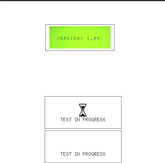
Power-Up Screen
Below is an example of the Software Version displayed during power-up.
Fig. 5-3 Power-Up Screen
Tone Selection Screen
Refer to Chapter 15 – Adjustments for descriptions of the Tone Selection Screens.
User-Initiated and Pre-Activation Test Screens
The generator will cycle between the following two screens, displaying each screen briefly, for the duration of the time that the system is in the User-Initiated Test state and Pre-Activation Test state. Refer to
Chapter 7 – Safety and Function Testing for details.
Fig. 5-4 Test in Progress Screens
Standby, Ready and Run Screens
The Standby, Ready, and Run screen appearances depend on the mode in which the system is running. In Normal mode, the Standby, Ready, and Run screens are the same and indicate the MAX power level of 5 on the right, and the user selected MIN power level on the left (1 to 5). In Developer/Biomed mode, the Standby screen indicates the user selected MIN power level on the left, and a subset of system parameters on the right. In Developer/Biomed mode, the Ready screen displays the user selected MIN Power level on the left (1 to 5) and the system run time parameters on the right. Developer/Biomed Run screen is identical to the Developer/ Biomed Ready screen.
GEN04 |
Go to www.e-ifu.com for the latest version of this manual. |
17 |
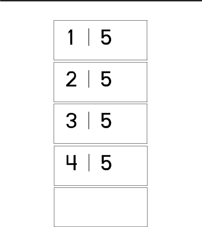
Service Manual
The following are all possible screens for the Standby, Ready, and Run states in Normal mode. The number on the left indicates the power level for MIN activation (1 to 5), and the number on the right is the power level for MAX activation.
Fig. 5-5 Standby, Ready and Run Screens in Normal Mode
Error Screens
Refer to Chapter 9 – High-Level System Troubleshooting for examples of each of these screens.
18 |
Go to www.e-ifu.com for the latest version of this manual. |
GEN04 |
Chapter 5 - Operation
System Operation
For an understanding of system operation, refer to the Harmonic Generator 300 System User Manual for instructions and specifications for use of the Harmonic Generator 300 System, Foot Switch, and Cart. Refer to package inserts provided separately for information about the Hand Piece, Hand Switching Adaptor, Adaptors, Test Tip and Instruments prior to using the system. This manual is not a reference to surgical techniques.
After completing system setup, the system may be operated.
1Place the generator in Ready mode by depressing the STANDBY button.
Note: In the Ready mode, for self-diagnostic purposes, the system sends a low-amplitude signal to the blade, causing the blade to vibrate slightly. This vibration does not pose a risk to the user.
2System check and activation:
Each time the generator is activated after exiting Standby, hold the instrument in the air (if coagulating shears are used, open the clamp arm) and depress the MIN or MAX power level on the foot switch or hand switching adaptor. “TEST IN PROGRESS” will appear on the graphic display and a rapid two-tone pulse will sound while the test is occurring. During this five-second period, a system check is being performed.
•If the system is operating properly, the activation tone corresponding to the power level activated will be heard when the check is complete. Stop activation, position the instrument on tissue, and resume activation.
•If the system is not operating properly, an error code will appear (refer to Chapter 9 – High-Level
System Troubleshooting or the Troubleshooting Guide located on top of the generator unit).
Warning: To avoid user or patient injury, ensure that the instrument is clear of other instruments, drapes, the patient or other objects during the system check. Safety measures (in accordance with hospital protocol) taken in the presence of aerosols should be in effect during the system check.
Note: The foot switch or hand switch must be depressed until the system check is complete. If the switch is released prematurely, the check will reinitiate at the next activation.
Note: The HAND ACTIVATION button on the generator control panel must be illuminated for the hand switch to be active. To deactivate the hand switch, depress the HAND ACTIVATION button (if the HAND ACTIVATION button is not illuminated, hand switch will be inactive).
Note: If the hand switch will not turn off during operation, depress the button corresponding to the power level opposite that being activated to turn it off - an alarm will sound. Press the HAND ACTIVATION button to disable the hand switching adaptor. Place the generator in Standby, and replace the hand switch; or, continue using the foot switch after deactivating the hand switch.
3If the system senses a generator, hand piece, or instrument fault during use, an audible alarm (tone with long pulses) will sound and a visual alarm indicator will appear on the control panel. (Refer to Chapter 9 – High-Level System Troubleshooting or the Troubleshooting Guide on top of the generator unit to resolve the problem.)
Warning: Place the generator in Standby before removing or replacing an instrument, hand switching adaptor or hand piece or when the system is not in use.
GEN04 |
Go to www.e-ifu.com for the latest version of this manual. |
19 |

Service Manual
System Shutdown
1Turn the generator power switch off and remove power cord from outlet.
2Disconnect the hand piece, instrument, and adaptor or hand switching adaptor (if used) and process them as indicated in their respective package inserts.
3Clean the generator and cart and disinfect the foot switch(es) following hospital protocol. Refer to the Harmonic Generator 300 System User Manual for detailed Cleaning and Disinfection instructions.
4Store foot switch(es) on the cart shelves provided. Each shelf will hold one foot switch.
5Wrap foot switch cable(s) and the power cord on the cart’s back handle for storage.
20 |
Go to www.e-ifu.com for the latest version of this manual. |
GEN04 |

Chapter 6 - Cleaning and Disinfection
Generator and Cart Cleaning
Clean generator and cart following hospital protocol. Before cleaning, turn the generator main power off and unplug the power cord from the grounded electrical outlet.
Warning: Spilling or spraying fluids on or into the generator or immersing the generator may result in damage to the generator and risk of shock or fire hazard.
Refer to the Harmonic Generator 300 System User Manual for detailed Cleaning and Disinfection instructions.
Foot Switch Cleaning
The foot switch and cable should be cleaned after each use.
Refer to the Harmonic Generator 300 System User Manual for detailed Cleaning and Disinfection instructions.
Disinfection (Generator, Footswitch and Cart)
Surface disinfection of the Generator, Foot Switch and Cart should follow the cleaning process. Particular attention to the disinfectant manufacturer’s recommendations must be followed for equipment that is knowingly and/or visibly contaminated with blood or bodily fluid. The foot switch can be immersed in the disinfectant solution.
Note: Keep the footswitch cable connector that connects to the generator dry at all times.
Refer to the Harmonic Generator 300 System User Manual for detailed Cleaning and Disinfection instructions.
GEN04 |
Go to www.e-ifu.com for the latest version of this manual. |
21 |

Service Manual
22 |
Go to www.e-ifu.com for the latest version of this manual. |
GEN04 |

Chapter 7 - Safety and Function Testing
Test the hand piece, generator, and foot switch for safety and function according to hospital protocol. Refer to individual package inserts for safety and function testing for other multi-patient use components.
Safety Test
Generator: A qualified hospital technician should perform a leakage current test.
Foot Switch: Examine the foot pedals, cable connectors, and cable for cracks or other damage and replace if damaged.
Other Components: Examine the components by following the instructions in their individual package inserts.
Function Test
1Attach the hand piece to the generator as described in Chapter 4 – System Setup, then attach the test tip rather than an instrument.
2Verify that the orange STANDBY indicator is illuminated.
3Push the STANDBY button to leave Standby mode and enter Ready mode.
Note: In the Ready mode, for self-diagnostic purposes, the system sends a low-amplitude signal to the blade, causing the blade to vibrate slightly. This vibration does not pose a risk to the user.
4Verify that the green READY indicator is illuminated.
5Verify that MIN Power Level 3 and MAX Power Level 5 are displayed.
6Push the Increase and Decrease Power Level button up and down to confirm the MIN Power Level changes from 1 to 5.
7Turn the generator off. Wait five seconds, then turn the generator back on. Wait ten seconds, then confirm MIN Power Level 3 and MAX Power Level 5 are displayed. Confirm the generator is not being activated unexpectedly.
8Press the TEST button to perform a User-Initiated Test. The system will run a series of tests to ensure the generator and hand piece are in proper working condition.
9Place the generator in Ready mode by depressing the STANDBY button. Hold the hand piece so that the distal portion is in the air and step on the MAX foot switch pedal (before activation begins, a fivesecond system check will be performed – “TEST IN PROGRESS” will appear on the display). After the test is completed, verify that the MAX Power Level indicator on the control panel flashes and that the MAX activation tone is heard.
Warning: To avoid user injury, ensure that the test tip is clear of tissue, other instruments, or other objects before activating the system.
10Hold the hand piece so that the distal portion is in air and step on the MIN foot switch pedal. Verify that the MIN Power Level indicator on the control panel flashes and that the MIN activation tone is heard.
Warning: To avoid user injury, ensure that the test tip is clear of tissue, other instruments, or other objects before activating the system.
GEN04 |
Go to www.e-ifu.com for the latest version of this manual. |
23 |

Service Manual
24 |
Go to www.e-ifu.com for the latest version of this manual. |
GEN04 |
 Loading...