

Page 1
ETC® Installation Guide
Unison Paradigm Touchscreen Rack Panel
Overview
The Unison® Paradigm™ Touchscreen uses a high-resolution, 7”-wide screen, color liquid-crystal
display (LCD) that is bright and easy to read, with controllable back lights. The Touchscreen is installed
in a rack panel, which is shipped separately. The Touchscreen is also available in locking cover and wall
mount configurations. The Touchscreen is powered by either LinkPower and Auxiliary power or PoE
(Power Over Ethernet 802.3af).
• Echelon® LinkPower® (LinkConnect) control network utilizing Belden 8471 (or approved equal) and 24 Vdc
Auxiliary power (two 16 AWG 1.5mm2) wires.
• PoE (Power over Ethernet 802.3af) utilizing Category 5 cable (or approved equal).
All control wiring should be installed and terminated by a qualified installer and should follow standard
wiring installation practices. Leave approximately 10 inches (254mm) of wiring in the backbox for
connection and to allow slack for future service needs. For more information about terminating Cat5
cable, refer to the ETC Ethernet Cat5 Termination Kit Setup Guide.
Installing the Collar
Installation should follow local codes and standard practices. Ensure that all wiring is installed correctly.
The touchscreen is su
electrical supplies.
Paradigm Touchscreen Model
pplied with an installation kit which includes the necessary hardware and
P-LCD-RBB Paradigm Touchscreen rack panel
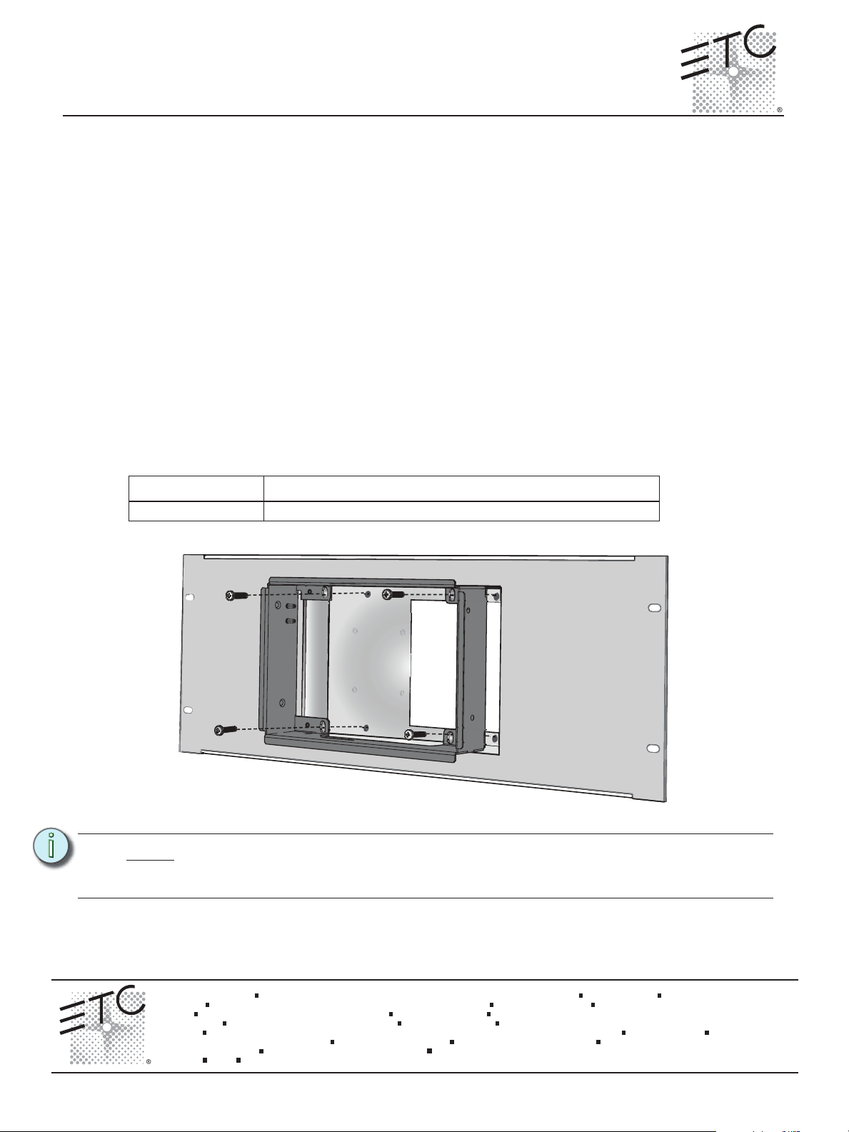
Step 1: Slide the collar into the rack panel.
Note:
It is important to orient the rack panel with the cutout on the right side to provide better
cable access between the Touchscreen and the Termination PCB. As well the collar
should be installed with the double mounting pin on the top.
noitpircseDledoM
Step 2: Install and tighten four M4 x 20mm collar mount screws through the collar into the rack
panel.
Corpora te Headquarters
London, UK
Rome, IT
Holzkir chen , DE
Hong Kon g
Service:
Web:
7184M21 20
Unit 26-28, Vi ctoria Industrial Estate, Victoria Road, London W3 6UU, UK Tel +44 (0)20 88 96 1000 Fax +44 (0)20 8896 20 00
Via Ennio Quirino Visconti, 11, 00193 Rome, Italy Tel +39 (06) 32 111 683 Fax +4 4 (0)20 8896 2000
Rm 1801, 18/F, Tower 1 Ph ase 1, Enterpr ise Square, 9 Sheung Yuet Road, Kowloon Bay, Kowloon, Hong Kon g Tel +852 2799 122 0 Fax +852 2799 9325
(Amer icas) service@e tcconnect.com (UK) service@etceur ope.com (DE) techserv-ho [email protected] m (Asia) [email protected]
www.etcconnect.com
Rev B Rel eased 200 9-12
3031 P leasant View Road, P.O. Box 620979 , Middleton, Wisconsin 53562-0 979 USA Tel +608 831 411 6 Fax +608 836 1736
Ohms trasse 3, 83607 Holzkirc hen, Germa ny Tel +49 (80 24) 47 00-0 Fa x +49 (80 24 ) 47 00-3 00
Copyright © 2009 ETC. All Rights Reserve d. Product inf ormation and specifications subject to change.
ETC intends this d ocument to be provided in its entirety.
.cnI ,slortnoC ertaehT cinortcelE4 fo 1 egaPlenaP kcaR neercshcuoT mgidaraP nosinU
Page 2
ETC Installation Guide
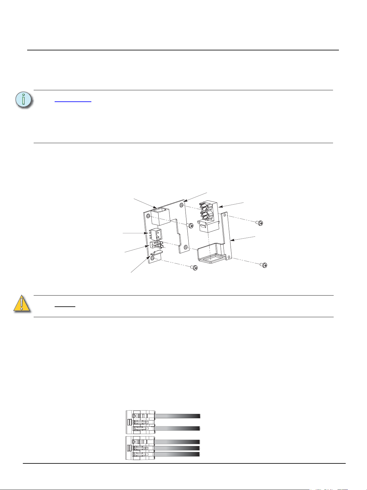
Ground spade
PCB
24 Vdc Aux
power
connector
RJ45
Mounting bracket
ULP connector
RJ45 Ethernet with
(PoE to Touchscreen)
RJ11 connector
(provides LinkPower and
Aux power to Touchscreen)
topology of a single
station installation
topology of multiple
stations installed in
series
Installed control wire
Pigtail wire
Installed control wire
Installed control wire to next station
Pigtail wire
Installing the Termination PCB
The printed circuit board (PCB) assembly is designed to accommodate either Ethernet or LON
connections. Prior to installing the PCB, terminate all necessary wiring. The PCB is installed on the
back side of the rack panel.
Paradigm P-LCD Series
CAUTION:
The PCB consists of three parts:
• PCB with female RJ11, LinkPower connector, 24 Vdc (Aux) connector, and ground spade
• RJ45 with punch down wire termination
• Mounting bracket and screws
Only one network type may be connected to the touchscreen. Damage will occur if
both power types, Auxiliary power and PoE, are connected to the Touchscreen.
ETC requires that all backboxes are grounded in accordance with local electrical
codes.
The RJ11 connection must be used to provide a ground connection from the backbox
to the touchscreen even when Ethernet connectivity is used.
Connecting Ethernet
Note:
Connecting LinkPower and Auxiliary Power
Use the provided WAGO CAGE CLAMP® connectors to terminate the wiring to the provided LinkPower
(black and white twisted pair) and Auxiliary power (red and black twisted pair) and ground wire pigtails.
Strip the ends of each wire (both installed control wires and pigtail wires) approximately 3/8” (10mm).
Unison Paradigm Touchscreen Rack Panel Page 2 of 4 Electronic Theatre Controls, Inc.
All Ethernet terminations must follow IEEE 802.3 and be terminated to the T568B
standard.
Step 1: Terminate the network wiring in the RJ45 punch down strip using a standard 110 punch
Step 2: Snap the RJ45 connector into the bracket.
Step 1: Terminate the installed LinkPower wiring to the white and black LinkPower pigtail. Using
down tool (not provided). Reference the connector label for the CAT5e wire termination
color code. The punch down connector provides insulation displacement. Do not strip the
wires.
two Wago connectors connect (typically white) installed wire(s) with white pigtail wire and
connect the (typically black) installed wire(s) with black pigtail wire as shown below.
Page 3
ETC Installation Guide
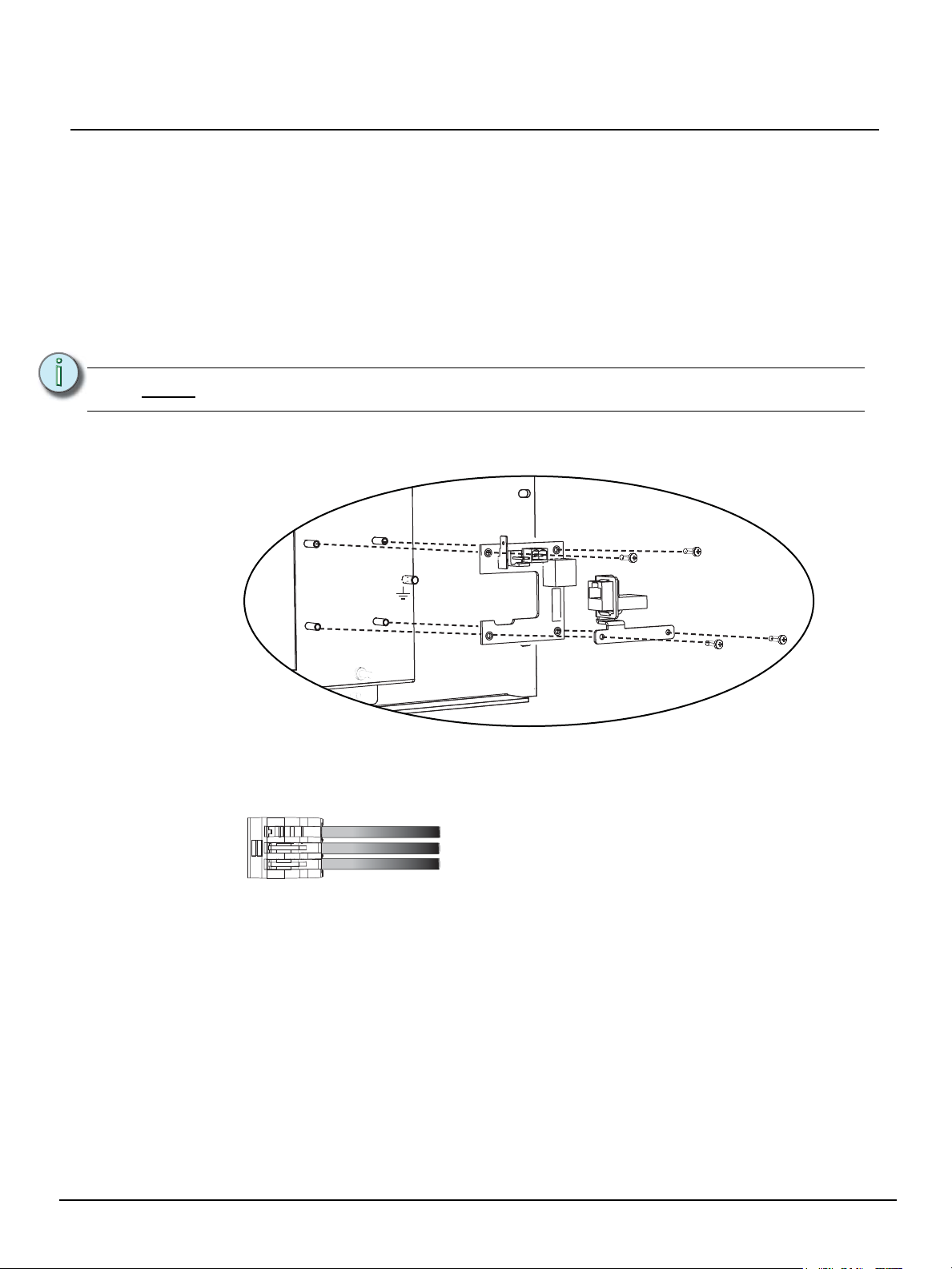
Installed ground wire
Ground wire pigtail (spade connector to the termination PCB)
Ground wire pigtail (ring terminal connected to the rear rack panel)
Step 2: Plug the LinkPower connector into the two pin LinkPower receptacle on the termination
PCB.
Step 3: Terminate the installed Auxiliary power wire to the red and black Auxiliary power pigtail
wires. Using two Wago connectors connect the (typically red) installed wire(s) with red
pigtail wire and connect the (typically black) installed wire(s) with black pigtail wire.
Step 4: Plug the Auxiliary power connector into the two pin Aux power receptacle on the
termination PCB.
Installing the Termination PCB to the Rack Panel
Step 1: Position the PCB on the four standoffs on the back of the rack panel and secure with two
M3x10mm pan head screws on the RJ11 side of the PCB only.
Paradigm P-LCD Series
Note:
Step 2: Place the bracket and RJ45 assembly (if used) on top of the PCB. Secure the PCB to the
Step 3: A ground connection is required for all Touchscreen assemblies. Using one three position
The termination PCB can be installed in any orientation to accommodate wiring.
backbox through the remaining holes in the PCB with two M3x10mm pan head screws.
Wago connector, connect the (typically green and yellow) installed wire(s) with the ground
wire pigtail (with attached spade), provided in the installation kit, and the ground wire
attached to the rack panel.
Unison Paradigm Touchscreen Rack Panel Page 3 of 4 Electronic Theatre Controls, Inc.
Page 4
ETC Installation Guide
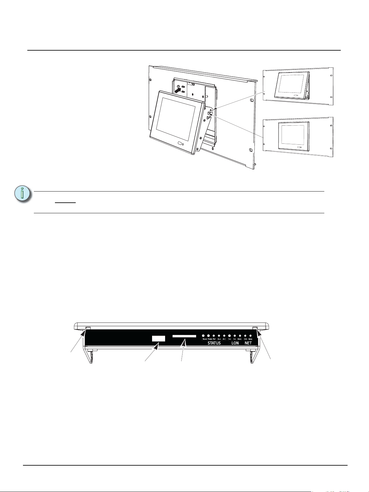
Service position
Operating position
The Touchscreen bracket is
designed for two positions,
service and operation. When
installed so that the pins are
in the first slots on the
bracket, the Touchscreen is
angled at the bottom for
service.
SD card slot
USB Port
Pry slot
Pry slot
Installing the Touchscreen
Paradigm P-LCD Series
Step 1: Install the RJ11 control cable provided in the installation kit to the RJ11 jack on the
Note:
Step 2: Plug the other end of the cable(s) into the receptacles on the Touchscreen.
Step 3: Hold the Touchscreen at a slight angle and insert the top first and hook the bracket onto
Step 4: To move the Touchscreen from the service position to the operation position, lift up at the
Step 5: Push firmly in and down on the bottom corners of the bezel until it audibly snaps onto the
Step 6: To open or remove the Touchscreen, insert a flat bladed screwdriver into the pry slots and
termination PCB. Also attach the RJ45 control cable if PoE will be used for communication
and power.
The RJ11 cable provides the ground connection to the rack panel and must
always be installed.
the double pins on each side of the collar.
bottom and rotate the bottom inward.
collar. When properly installed, the Touchscreen should not easily unsnap from the collar.
unsnap the Touchscreen from the collar. Then lift the bottom upward slightly and rotate
outward.
Indicators
After the Touchscreen has been powered up, the appropriate LEDs on the service panel on the bottom
of the Touchscreen illuminate. The LCD displays a startup screen a few seconds after booting.
I/O Indicators
• Reset - when pressed, resets the Portable LCD software
• Mode - press once for Setup menu. Press and hold for 4 seconds to calibrate the Touchscreen
Unison Paradigm Touchscreen Rack Panel Page 4 of 4 Electronic Theatre Controls, Inc.
• PoE - indicates when the Touchscreen is powered by Power over Ethernet 802.3af
• Aux - indicates the Touchscreen is powered (Aux 24 Vdc)
• Act - application activity is detected
• Svc - when pressed, sends the stations Neuron ID to the connected processor
• Svc - service pin indicator
• Data (LON) - indicates LON network activity
• Link - indicates when the Ethernet interface has a valid link to the network
• Data (NET) - indicates Ethernet network activity
 Loading...