

Page 1

Assembly Guide
Zoom
Production Dates: September 2004 - Present
ATTENTION: The part numbers listed in this guide may differ from the parts
required for your particular Source Four fixture. Part numbers for
fixtures change occasionally as parts are replaced or upgraded.
To ensure that you are ordering the proper part for your specific
fixture, please contact your ETC dealer, or ETC Customer Service
for assistance.
Copyright © 2007 Electronic Theatre Controls, Inc.
All Rights reserved.
Product information and specifications subject to change.
Part Number:
7060M2550-06.01
Released: August 2007
Rev A
Page 2

Table of Contents
15°-30° Basic Fixture . . . . . . . . . . . . . . . . . . . . . . . . . . . . . . . . . . . . .1
25°-50° Basic Fixture . . . . . . . . . . . . . . . . . . . . . . . . . . . . . . . . . . . . .2
Assembling Basic Fixture . . . . . . . . . . . . . . . . . . . . . . . . . . . . . .2
Lamp Socket Assembly . . . . . . . . . . . . . . . . . . . . . . . . . . . . . . . . . . .3
Assemble lamp socket. . . . . . . . . . . . . . . . . . . . . . . . . . . . . . . . .4
Reflector Housing Assembly . . . . . . . . . . . . . . . . . . . . . . . . . . . . . . .7
Removing reflector. . . . . . . . . . . . . . . . . . . . . . . . . . . . . . . . . . . .7
Installing reflector. . . . . . . . . . . . . . . . . . . . . . . . . . . . . . . . . . . . .8
. . . . . . . . . . . . . . . . . . . . . . . . . . . . . . . . . . . . . . . . . . . . . . . . . . .8
Cleaning reflector. . . . . . . . . . . . . . . . . . . . . . . . . . . . . . . . . . . . .8
Front Barrel Assembly . . . . . . . . . . . . . . . . . . . . . . . . . . . . . . . . . . . .9
Assemble front barrel assembly . . . . . . . . . . . . . . . . . . . . . . . .10
15°- 30° Lens Tube . . . . . . . . . . . . . . . . . . . . . . . . . . . . . . . . . . . . .12
15°- 30° Lens tube assembly. . . . . . . . . . . . . . . . . . . . . . . . . . .13
15°- 30° Gel frame endcap assembly . . . . . . . . . . . . . . . . . . . .13
15°- 30° Front lens assembly. . . . . . . . . . . . . . . . . . . . . . . . . . .13
15°- 30° Rear lens assembly . . . . . . . . . . . . . . . . . . . . . . . . . . .13
25°- 50° Lens Tube . . . . . . . . . . . . . . . . . . . . . . . . . . . . . . . . . . . . .14
25°-50° lens tube assembly . . . . . . . . . . . . . . . . . . . . . . . . . . . .15
25°- 50° Gel frame endcap assembly . . . . . . . . . . . . . . . . . . . .15
25°- 50° Front lens assembly. . . . . . . . . . . . . . . . . . . . . . . . . . .15
25°- 50° Rear lens assembly . . . . . . . . . . . . . . . . . . . . . . . . . . .15
Assemble lens tube (15°-30° and 25°-50°) . . . . . . . . . . . . . . . .16
Cleaning glass lens . . . . . . . . . . . . . . . . . . . . . . . . . . . . . . . . . .17
ETC®, Emphasis®, Expression®, Insight™, Imagine™, Focus™, Express™, Unison®, Obsession® II, ETCNet2™,
EDMX™, Source Four
of Electronic Theatre Controls, Inc. in the United States and other countries.
All other trademarks, both marked and not marked, are the property of their respective owners.
i Table of Contents
®
, Revolution®, Sensor®, and WYSILink™ are either registered trademarks or trademarks
Page 3

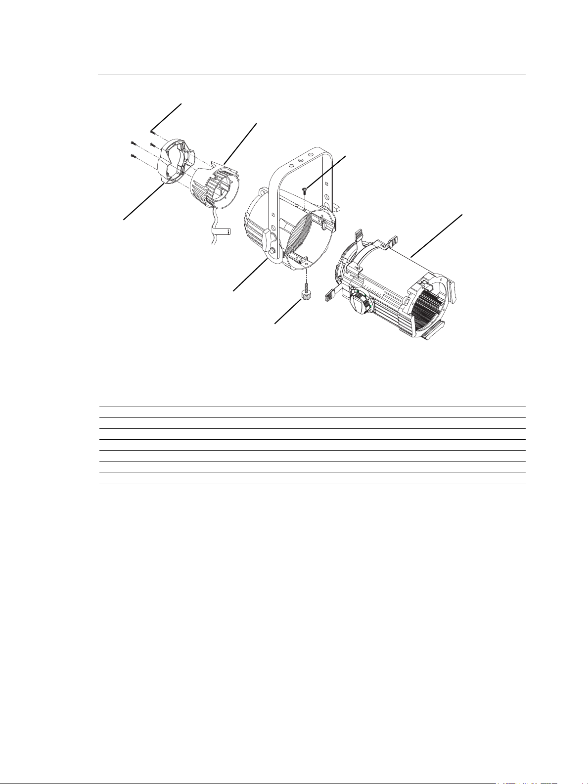
15°-30° Basic Fixture
1
2
3
4
5
6
7
9
Figure 1
8
Reference
Number
1 7060A2030 15°-30° lens tube 1
2 7060A2020 Reflector housing assembly, double clutch 1
3 7060A2008 Lamp socket assembly 1
4 7060A4008-01 Knob set with male insert 1
5 7060A4037 Handle, insulated rear 1
6 HW5197 Screw, 1/4-20 x 5/8, black zinc 1
7 HW2181 Screw, 6-32 x 3/4, black Taptite 4
8see page 9 Front barrel assembly
9 7060A2028 Balance Yoke 1
Part
Number
Optional
Description Quantity
Required
15°-30° Basic Fixture 1
Page 4
25°-50° Basic Fixture
Figure 2
1
2
3
4
5
6
7
Reference
Number
1 7060A2032 25°-50° lens tube 1
2 7060A2020 Reflector housing assembly, double clutch 1
3 7060A2008 Lamp socket assembly 1
4 7060A4008-01 Knob set with male insert 1
5 7060A4037 Handle, insulated rear 1
6 HW5197 Screw, 1/4-20 x 5/8, black zinc 1
7 HW2181 Screw, 6-32 x 3/4, black Taptite 4
Assembling Basic Fixture
Step 1: Follow instructions under Assemble lamp socket, page 4.
Step 2: Follow instructions under Installing reflector, page 8.
Step 3: Follow instructions under Assemble front barrel assembly, page 10
Step 4: Follow instructions under Assemble lens tube (15°-30° and 25°-50°), page 16.
Step 5: Insert lens tube assembly (1) fully into the reflector housing assembly (2). Turn
Step 6: Install the lamp socket assembly (3) to the reflector housing (2) and secure with
Step 7: Release the gel retaining clip by pushing it sideways while gently pulling
Step 8: Insert the color frame.
Step 9: Lock the clip by pushing sideways while gently pushing it forward.
Part
Number
lens tube assembly 1/4 turn and align the two mounting holes. Secure with screw
(6) on top, and knob (4) on bottom. Tighten both securely. See Figure 1 or Figure
2.
brass knurled screw on rear of lamp socket assembly.
backwards.
Description Quantity
Required
2 Source Four Zoom Assembly Guide
Page 5
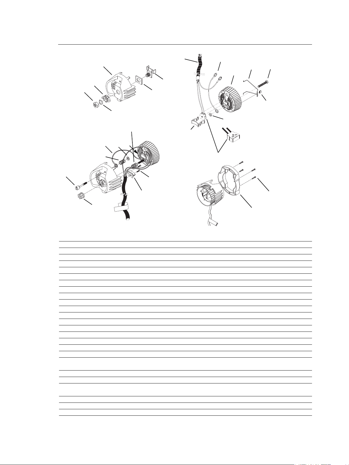
Lamp Socket Assembly
6
5
1
13
14
20
21
9
10
22
2
25
17
18
23
24
11
4
3
8
12
15
16
19
7
22
Figure 3
Reference
Number
1 7060A3055 Housing, socket, casting, painted 1
2 7060A3007 Socket, light baffle casting, raw 1
3 7060A4007 Knob, X-Y, lamp set 1
4 7060A4008-02 Knob, Z, lamp set w/female insert 1
5 7060A4011 Bushing, cup 1
6 7060A3011 Hub, index, casting 1
7 7060A3012 Spring, lamp retainer 1
8 HW748 Spring, compression 1
9 7060B7019 Complete UL socket assembly 1
10 HW534 Nut, hex, 1/4-20, black zinc 1
11 7060A3025 Screw, 1/4-20 knurled head 1
12 HW746 Retaining ring, flat, Southco 1
13 HW5123 Nut, hex, 9/16-18, black zinc 1
14 HW747 Washer, wave 1
15 7060A3056 Clamp, strain relief, painted 1
16 HW3103 Screw, 8-32 x 5/8 PhFHMS, black zinc 2
17 HW5122 Bolt, 1/4-20 x 1.75, full thread, black zinc 1
18 HW8209 Clip Tinnerman 1
19 7060B7003
20 W6195 36" sleeve, fiberglass 1
21 HW749 Spring, ground 1
22 7060B7007
23 7060A4037 Handle, insulated rear, black 1
24 HW2181 Screw, 6-32 x 3/4, Taptite 4
25 7060A3085 Source Four Lamp Retainer Wire 1
Part
Number
Description Quantity
Required
48" W420 wire, 16 gauge, 200° C/300V, green UL 1180/CSA AWM
with lug J490T installed
4" W420 wire, 16 gauge, 200° C/300V, green, UL 1180/CSA AWM
with two J490T lugs installed
1
1
Lamp Socket Assembly 3
Page 6
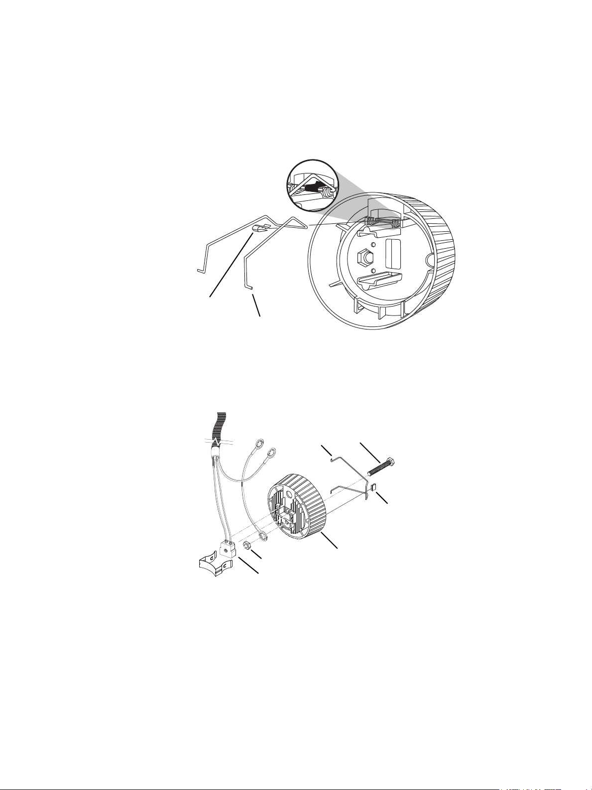
Assemble lamp socket
18
25
Figure 4
18
17
2
22
19
25
97
10
Figure 5
Tools Required:
• Open-end adjustable wrench or a 7/16” socket
• Needle-nose pliers
• #2 Phillips screwdriver
Step 10: Set the crossbar of the retainer clip (25) under the two hooks on the clip bracket
as shown in Figure 4.
Step 11: Place the Tinnerman clip (18) over the retainer clip crossbar between the two
hooks and press it down firmly until it snaps into place.
Step 12: Insert the bolt (17) through the light baffle socket casting (2). See Figure 5.
Step 13: Install the green ground wire assemblies (19 and 22) on the bolt (17) with the
prongs on the crimped connectors toward the casting. Run both wires through
the indent in the lip around the bolt hole. Secure with nut (10) and tighten
securely (60 inch pounds).
Step 14: Place the socket assembly (9) into the light baffle socket casting (2). Be sure it is
well seated.
4 Source Four Zoom Assembly Guide
Page 7
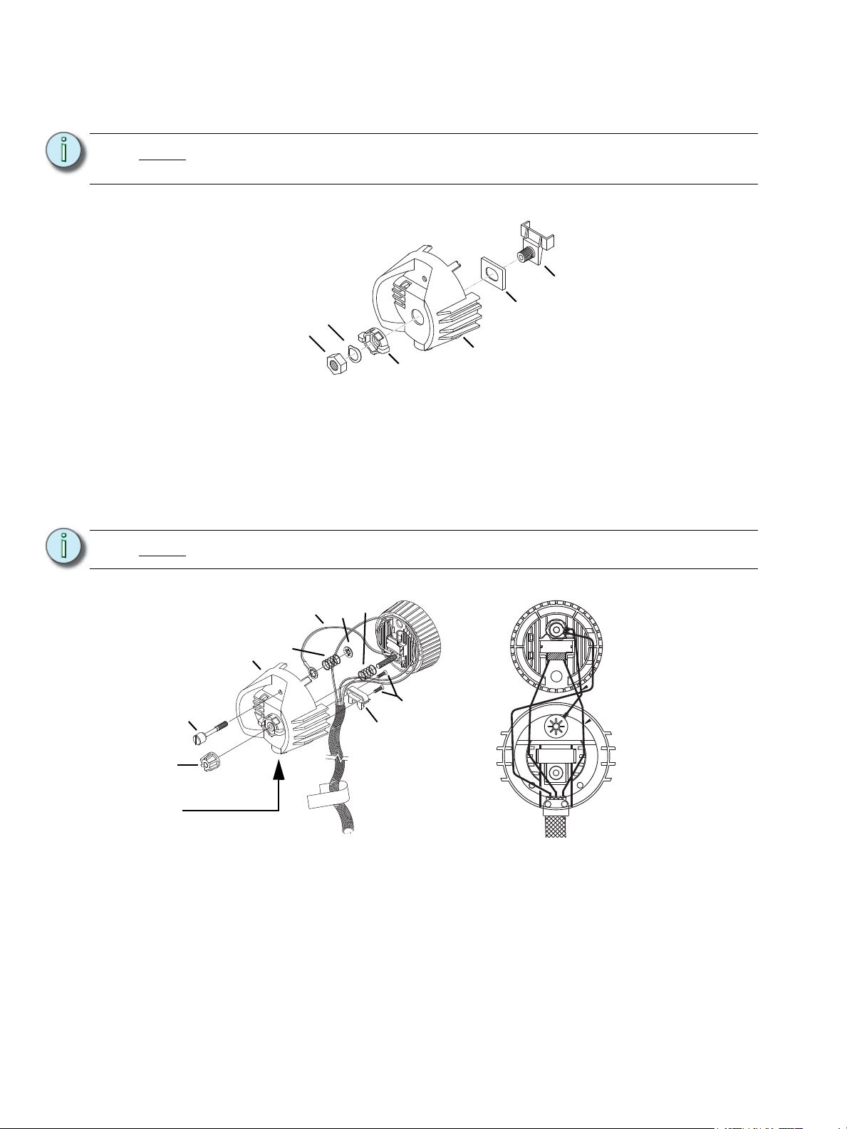
Step 15: Install the lamp retainer spring (7). The lamp retainer spring secures the socket.
5
1
6
14
13
3
Figure 6
11
15
1
222112
Cable Clamp in
Housing
16
8
4
Figure 7
Figure 8
Insert the spring one end at a time, making sure the rectangular slot in each side
of the spring seats on the corresponding tab in the casting.
Note:
Note:
If the spring does not seat correctly, coax it into place with a screwdriver or needlenose pliers.
Step 16: Install the bushing cup (5) into the housing socket casting (1) as shown in Figure
6. The cup should slide smoothly up and down, but not side to side.
Step 17: Insert the threaded end of the index hub (6) through the holes in the bushing cup
and the back of the housing socket casting (1).
Step 18: Slide the X-Y knob (3) over the exposed index hub bolt (6), then insert the wave
washer (14) on the bolt and secure with the 9/16 hex nut (13). Hand tighten the
X-Y knob (3).
Install the wave washer with the upward curve toward the hex nut.
Step 19: Insert the knurled head screw (11) through the housing socket casting (1) as
shown in Figure 7.
Step 20: Install the shorter green ground wire (22) onto the screw. The prongs on the
Step 21: Install the ground spring (21) onto the screw and secure it with the Southco flat
Lamp Socket Assembly 5
crimped connector should be toward the casting.
retaining ring (12). Install the Southco ring with its prongs away from the casting.
Page 8
Note:
Use pliers to straighten the Southco retaining ring (12) if it bends when you install
it on the bolt.
Step 22: Lay the leads in the bottom half of the cable clamp (located in the housing socket
casting [1]), making sure that the fiberglass sleeving extends slightly past the
screw holes in the housing socket casting. Install new sleeving if necessary.
Then, route the wires as shown in Figure 8.
CAUTION:
Step 23: Install the top half of the cable clamp (15) and secure it with the two screws (16).
Note:
Step 24: Using the four screws (24), attach the handle (23) to the lamp socket assembly.
Step 25: Place the compression spring (8) on the protrusion on the inside of the index hub
Step 26: Insert bolt (17) through spring (8) and through the index hub (6) of the housing
Step 27: Before proceeding, check again to make sure the wires are still positioned as
Step 28: Press the two castings together firmly so the bottom of the light baffle (2) sits on
You must follow the wire routing diagram to ensure that the socket leads do not
interfere with the lamp focus mechanism.
Tighten the screws alternately to ensure a solid connection.
To ensure that the clamp holds the cable tightly, flatten the cable, then fold over
the sleeving before you install the top half of the clamp. Make sure the top edge
of the cable clamp is even with the edge of the socket to prevent interference with
lamp focus movement. Make sure sleeving is not pinched.
See Figure 3.
(6).
socket (1), joining the two castings. Make sure wires are not pinched between
the two pieces.
indicated in Figure 6. Adjust if necessary.
top of the cable clamp (15), then install the X-Y lampset (3) and Z lamp knob (4).
Hand tighten the knob all the way to the right.
CAUTION:
6 Source Four Zoom Assembly Guide
You must install Z knob as described above to ensure proper lamp focus travel.
Page 9
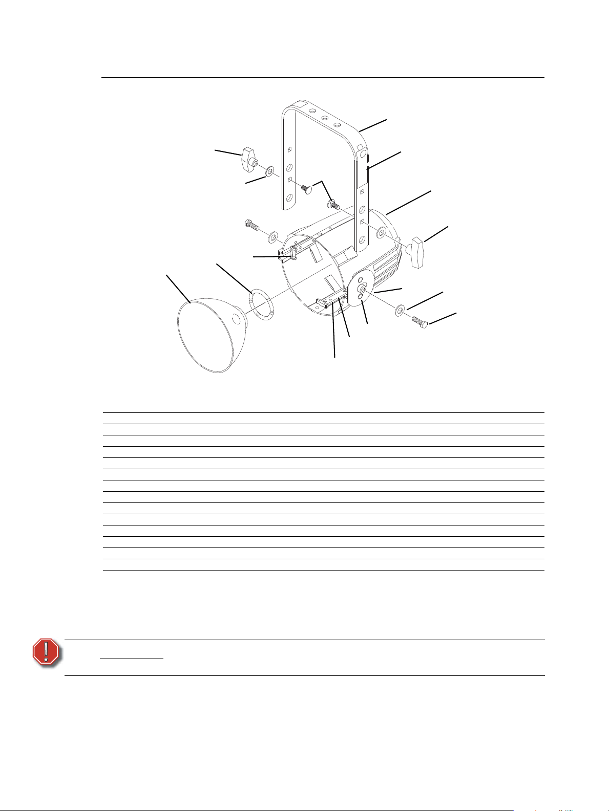
Reflector Housing Assembly
SOURCE FOUR
UL
Figure 9
7
1
8
10
4
11
9
6
5
12
3
2
13
(2 required)
(4 required)
(4 required)
(4 required)
14
8
10
Reference
Number
1 7060A3054 Housing, reflector casting, painted black 1
2 7060A3006 Clip, reflector retainer 4
3 7060A4010 Bushing, gate 4
4 7060A3016 Plate, clutch 1
5 7060A3019 Spring, reflector support 1
6 7060A4015 Reflector, molded glass, coated 1
7 7060A3058 Bracket, yoke, painted 1
8 HW8144 Handle, yoke knob, 5/16 - 18 2
9 HW753 Rivet, machine, 3/16 x.720, flat head, black zinc 2
10 HW5126 Washer, flat, 5/16, black zinc 4
11 HW5193 Bolt 5/16-18 x 3/4, black zinc 2
12 HW5125 Bolt, carriage, 5/16-18 x.75, black zinc 2
13 HW752 Rivet machine, 3/16 x 5/16, black zinc 4
14 7060A4088 Label, S4 750w UL 1
Part
Number
Removing reflector
Tools Required:
WARNING:
• Minimally padded work surface (cardboard, carpet, or rubber mat recommended)
This procedure may crack or break the reflector. Always wear gloves, safety
glasses, and a dust mask when performing this procedure.
Step 1: Place the reflector housing face down on your work surface so that the concave
reflector surface points downward.
Description Quantity
Required
Reflector Housing Assembly 7
Page 10
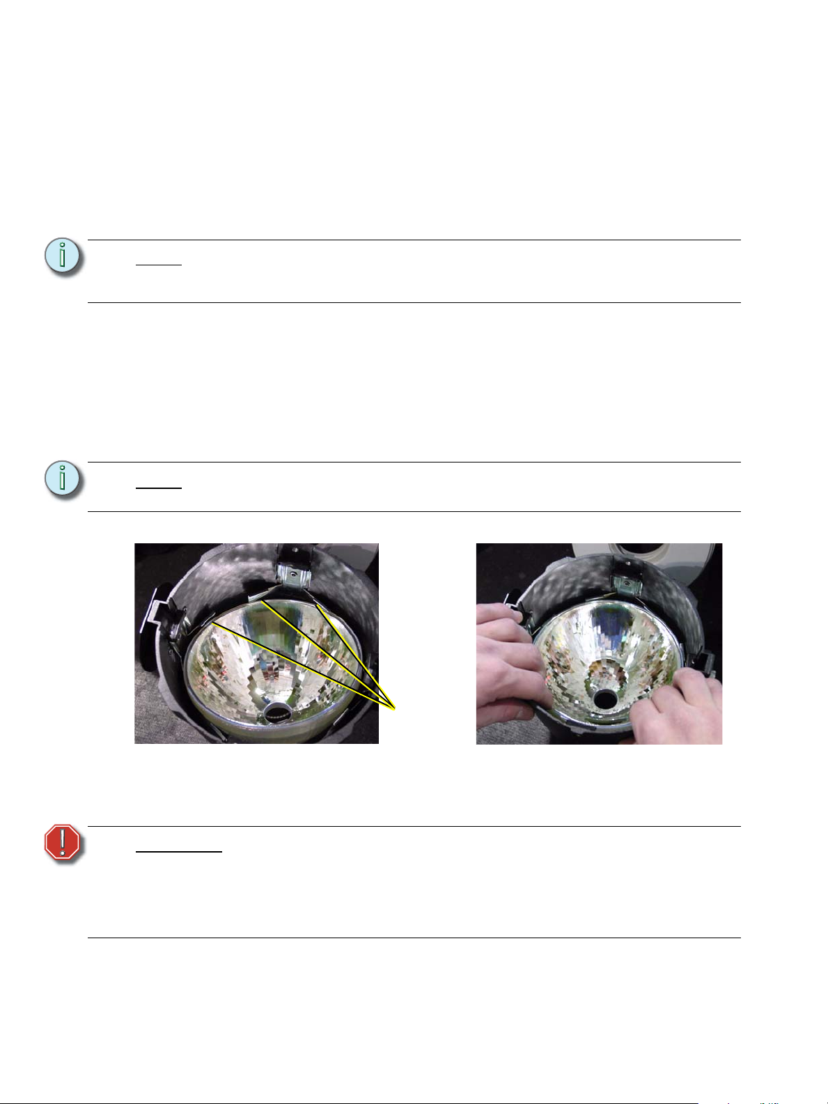
Step 2: Loosen the clutch and rotate the yoke so that it is perpendicular to the housing
Step 3 Step 4
Under three
adjacent clips.
at roughly a 90° angle. Tighten the clutch.
Step 3: Using the yoke as your handle, raise the housing assembly off of the work
surface a few inches and then firmly tap the housing on the work surface. This
should force the reflector out of its clips.
Step 4: Carefully lift the housing to see if the reflector is released. If it is not, repeat step
3 with slightly more force.
Installing reflector
Note:
Note:
The following assumes all four reflector retainer clips (2) have already been
riveted to the reflector housing casting (1) and the gate bushings (3) installed on
the retainer clips. See Figure 9.
Step 1: Place the reflector housing casting (1) on a flat work surface with the large
opening facing up.
Step 2: Install the reflector support spring (5) in the circular opening at the base of the
casting.
Step 3: Insert the reflector (6) at an angle, under any three adjacent legs of the reflector's
clips.
Step 4: Gently press down on the opposite side of the reflector until it snaps into place
under the remaining clips.
If the reflector does not snap in, turn the casting over. Gently pull on the side of
the reflector that has not snapped in until the rest of the reflector slides into place.
Cleaning reflector
WARNING:
Remove dust with a blast of oil-free air or wipe with a clean, lint-free cloth. Isopropyl alcohol,
distilled water or a 50%-50% mixture of each can be used to clean the glass surface.
8 Source Four Zoom Assembly Guide
Do not use ammonia-based or other harsh commercial cleaners. Clean
reflector only as directed.
Commercially available glass cleaning agents should be avoided as they
may contain ammonia, other harsh chemical detergents or abrasive agents.
These cleaners may damage the glass surface and the Anti-Reflective
coatings. Do not immerse or soak the glass in any cleaning solution.
Page 11
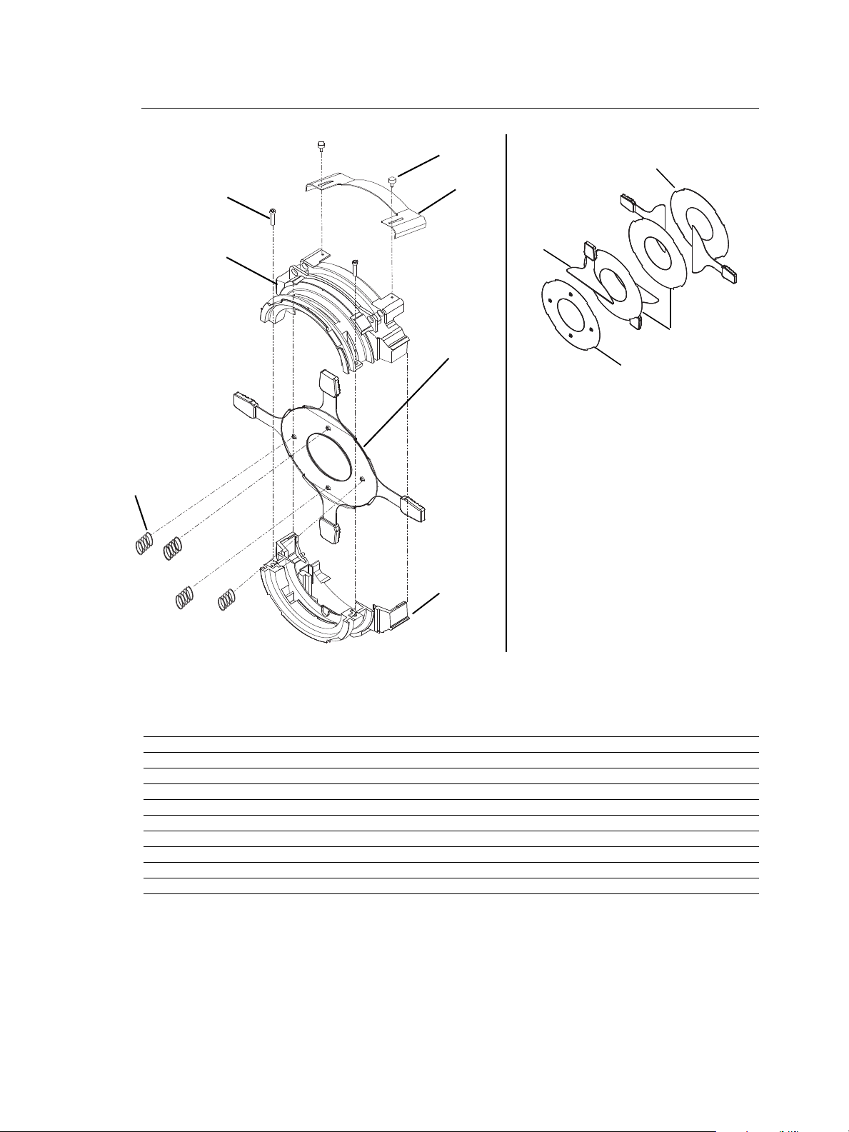
Front Barrel Assembly
Shutter Assembly: The bottom divider plate
(4) has four dimples punched into the surface;
the top plate (6) has none. The middle divider
plates (5) are noticeably thinner-gauge metal
than the other two.
See detail to
the right
3
5
6
4
Figure 10
Figure 11
10
9
8
7
1
2
3
4
5
6
Reference
Number
1 7060A3112 Front barrel, top casting, painted 1
2 7060A3113 Front barrel, bottom casting, painted 1
3 7060A2025 Shutter blade assembly, 22 gauge 4
4 7060A3001-01 Plate, divider with dimples (bottom) 1
5 7060A3003 Plate, gate (middle) 1
6 7060A3001-02 Plate, divider (top) 1
7 HW754 Shutter spring 4
8 HW3154 Screw, 8-32 x 5/8, PhPH, taptite, black zinc 2
9 7060A3099 Cover, iris slot 1
10 HW2177 Thumb Screw, 8-32 x 1/4, black zinc 2
Part
Number
Description Quantity
Required
Front Barrel Assembly 9
Page 12
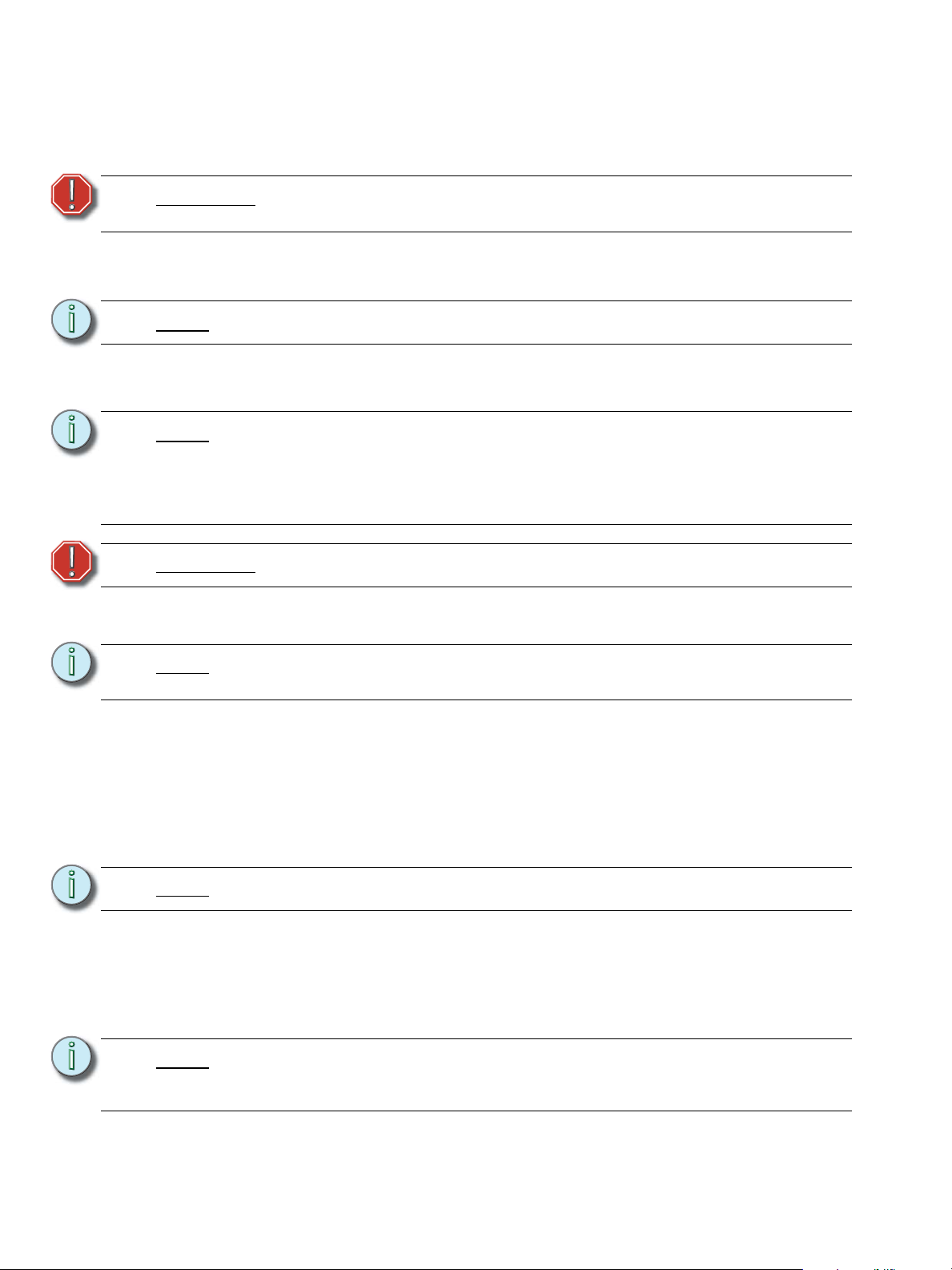
Assemble front barrel assembly
Tools Required:
• #2 Phillips head screwdriver
WARNING:
Step 1: See Figure 10. Stand the top and bottom front barrel castings (1 and 2) upright
Note:
Step 2: Slide the bottom divider plate (4) into its place in the bottom casting (2). The
Note:
WARNING:
Step 3: With the bottom barrel casting (2) to your left, place one shutter blade (3) on top
During assembly, the shutter springs can pop out of place. Always wear
protective eyewear during this procedure.
with the shutter end of the castings toward the bottom.
The top front barrel casting (1) contains the iris slot.
dimples on the divider plate must point down.
The bottom divider plate (4) has four dimples punched into the surface; the top
plate (6) has none. The middle divider plates (5) are noticeably thinner-gauge
metal than the other two.
The notches on the divider plates must fit against the flanges in the casting so the
plates do not move.
Divider plate edges are sharp. Handle with caution.
of dimpled divider plate (4) handle facing outward, up and down. (See Figure 11).
Note:
Note:
Note:
Install shutter blades with the rounded side facing up toward the front of the
casting.
Step 4: Place the middle gate plate (5) on top of the shutter blade.
Step 5: Place another shutter blade (3) on top of the divider plate and then place the
other divider plate on top.
Step 6: Place the two shutter blades on top of the divider. Pull the blade and plate
assembly slightly forward to allow the handle to slip through the slot in the bottom
casting.
Step 7: Place the top divider plate (6) on top of the two shutter blades.
Make sure no shutter assembly components are under the pattern holder guides.
Step 8: With both front barrel castings still standing upright, join the two halves, sliding
the handle of the top shutter blade through the slot in the top front barrel casting
(1).
Step 9: Connect the halves of the gate assembly using two PHMS screws (8). Hand
tighten only (25 inch pounds).
The tops of the two front barrel castings must be even. Adjust as necessary before
completely tightening the screws. Failure to do this could interfere with the barrel
rotation.
10 Source Four Zoom Assembly Guide
Page 13

Step 10: Turn the front barrel assembly over so that the narrower end is on your work
surface.
Step 11: Install the four shutter springs (7) between the four dimples in the shutter plate
and the tabs in the lip of the casting.
Note:
Install the springs at the joints in the castings on either of the tabs at the joint.
Step 12: Place iris slot cover (9) over the iris slot. Use two screws (10) to secure the cover.
Front Barrel Assembly 11
Page 14
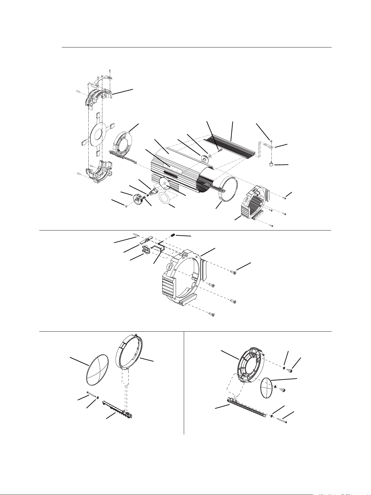
15°- 30° Lens Tube
Figure 12
15°-30° lens tube assembly
15°-30° Gel frame endcap assembly
15°-30° Front lens assembly
15°-30° Rear lens assembly
Figure 13
Figure 15
Figure 14
See Front Barrel Assembly, page 9
4
5
6
7
8
9
1
14
12
2
13
15
3
10
11
16
17
18
20
19
20
26
25
24
23
21
22
31
30
29
28
27
38
32
34
35
37
36
33
12 Source Four Zoom Assembly Guide
Page 15

15°- 30° Lens tube assembly
Reference
Number
1 7060A2030 15°-30° lens tube 1
2 7060A3139-01 Extrusion door 1
3 See below Front lens assembly 1
4 See below Rear lens assembly 1
5 HW5218 Nut, 1/4-20 metal lock Lowpro 1
6 7060A4056 Dial adjustment 1
7 7060A4066 Button, push, CAM lever 1
8 HW776 Spring, push-button 1
9 7060A4057 Lever, CAM 1
10 7060A4082 Zoom field angle label 1
11 7060A4054 Light baffle 1
12 7060A4058 Gear, spur 1
13 HW777 Wash spring 1
14 7060A4081 S4 Zoom angle label, 15-30 1
15 HW5224 Screw, 1/4-20 x 1-1/4, PHMS 1
16 HW8227 Retainer, 1/4 turn stud 1
17 7060A3114 Latch bracket 1
18 HW8225 Fastener, bail style 1
19 See below Gel frame endcap assembly 1
20 HW5217 Screw, 1/4-14 x 1, OHSL 1
Part
Number
Description Quantity
15°- 30° Gel frame endcap assembly
Reference
Number
20 HW5217 Screw, 1/4-14 x 1, OHSL 4
21 7060A3111 Endcap, gel frame, black 1
22 7060A3100 Gel clip 1
23 HW750 Spring retainer 1
24 HW8226 Receptacle, 1/4 turn stud 1
25 7060A3097 Plate, gel clip retainer 1
26 HW3185 Screw, 8-32 x 3/8, PHPH, Taptite 1
Part
Number
Description Quantity
Required
Required
15°- 30° Front lens assembly
Reference
Number
27 7060A4046 Front lens holder 1
28 7060A4050 Front gear rack 1
29 HW3118 Washer, flat #8, black 1
30 HW3114 Screw, 8-32 x 2, PHST, plastic 1
31 7060A4067 Front lens, glass 1
Part
Number
Description Quantity
Required
15°- 30° Rear lens assembly
Reference
Number
32 HW4117 Washer, flat, teflon 2
33 HW4112 Screw, #10-14 x 5/8, plastic 2
34 HW3118 Washer, flat #8, black 1
35 HW3114 Screw, 8-32 x 2, PHST, plastic 1
36 7060A4051 Rear gear rack 1
37 7060A4068 Rear lens glass 1
38 7060A4048 Rear lens holder 1
15°- 30° Lens Tube 13
Part
Number
Description Quantity
Required
Page 16
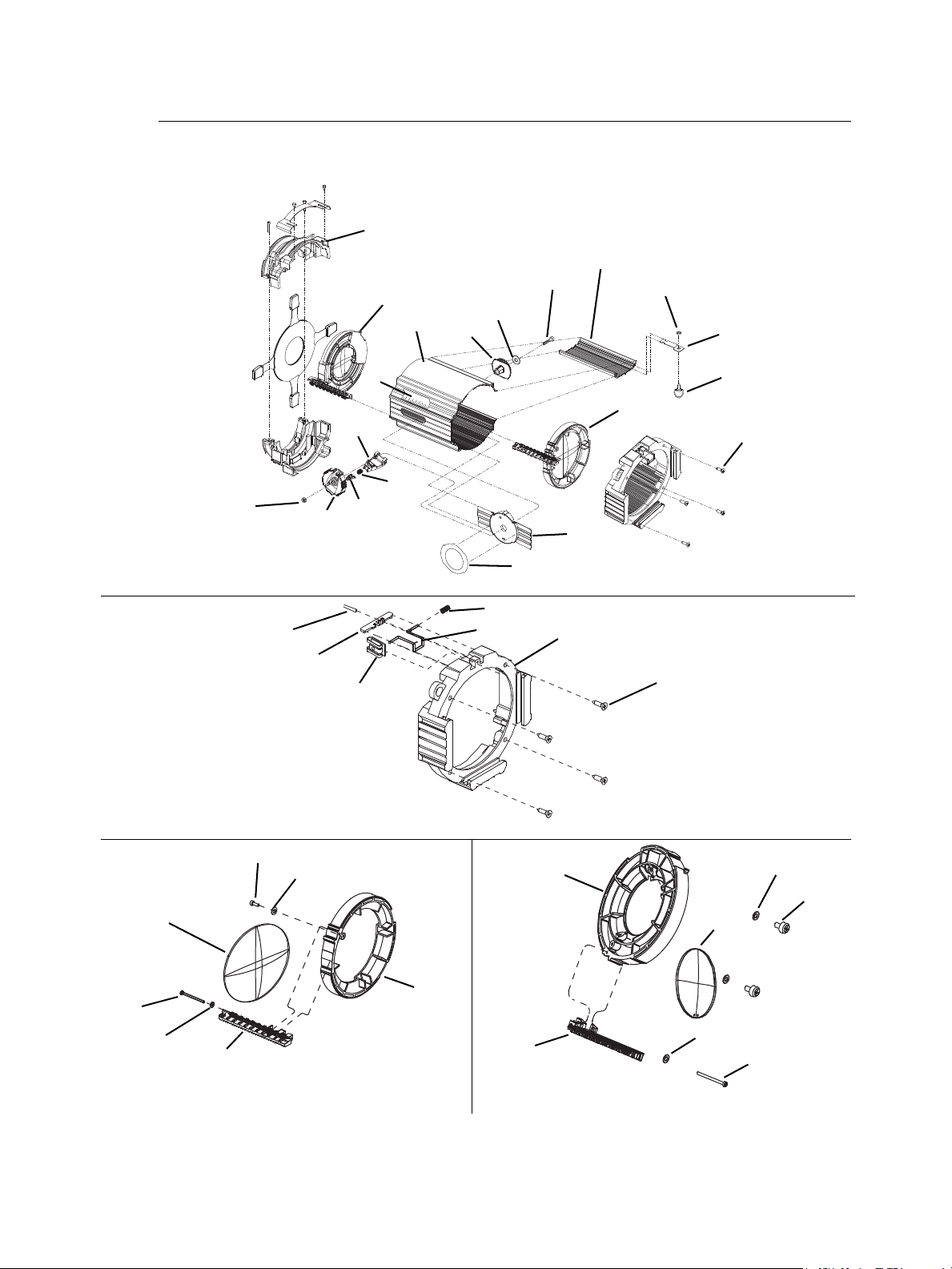
25°- 50° Lens Tube
Figure 16
25°-50° lens tube assembly
25°-50° Gel frame endcap assembly
25°-50° Front lens assembly
25°-50° Rear lens assembly
Figure 19
Figure 18
4
1
14
9
5
6
7
8
15
18
17
16
13
12
2
3
11
10
26
25
24
23
20
Figure 17
22
30
31
27
33
32
28
29
34
40
36
38
37
39
20
See Front Barrel Assembly, page 9
21
35
14 Source Four Zoom Assembly Guide
Page 17

25°-50° lens tube assembly
Reference
Number
1 7060A2032 25°-50° lens tube 1
2 7060A3139-02 Extrusion door 1
3 See below Front lens assembly 1
4 See below Rear lens assembly 1
5 HW5218 Nut, 1/4-20 metal lock Lowpro 1
6 7060A4056 Dial adjustment 1
7 7060A4066 Button, push, CAM lever 1
8 HW776 Spring, push-button 1
9 7060A4057 Lever, CAM 1
10 7060A4084 Zoom field angle label 1
11 7060A4055 Light baffle 1
12 7060A4058 Gear, spur 1
13 HW777 Wash spring 1
14 7060A4080 S4 Zoom angle label, 15-30 1
15 HW5224 Screw, 1/4-20 x 1-1/4, PHMS 1
16 HW8227 Retainer, 1/4 turn stud 1
17 7060A3114 Latch bracket 1
18 HW8225 Fastener, bail style 1
19 See below Gel frame endcap assembly 1
20 HW5217 Screw, 1/4-14 x 1, OHSL 1
Part
Number
Description Quantity
25°- 50° Gel frame endcap assembly
Reference
Number
20 HW5217 Screw, 1/4-14 x 1, OHSL 4
21 7060A3111 Endcap, gel frame, black 1
22 7060A3100 Gel clip 1
23 HW750 Spring retainer 1
24 HW8226 Receptacle, 1/4 turn stud 1
25 7060A3097 Plate, gel clip retainer 1
26 HW3185 Screw, 8-32 x 3/8, PHPH, Taptite 1
Part
Number
Description Quantity
Required
Required
25°- 50° Front lens assembly
Reference
Number
27 7060A4047 Front lens holder 1
28 7060A4052 Front gear rack 1
29 7060A4069 Front lens, glass 1
30 HW4112 Screw, #10-10 x 5/8, plastic 1
31 HW4117 Washer, flat, teflon 1
32 HW3118 Washer, flat #8, zinc 1
33 HW3114 Screw, 8-32, PHST, plastic 1
Part
Number
Description Quantity
Required
25°- 50° Rear lens assembly
Reference
Number
34 7060A4048 Rear lens holder 1
35 7060A4070 Rear lens glass 1
36 7060A4053 Rear gear rack 1
37 HW4117 Washer, flat, teflon 2
38 HW4112 Screw, #10 - 10 x 5/8, plastic 2
39 HW3116 Screw, 8-10 x 1-1/2 1
40 HW3118 Washer, flat #8, zinc 1
25°- 50° Lens Tube 15
Part
Number
Description Quantity
Required
Page 18
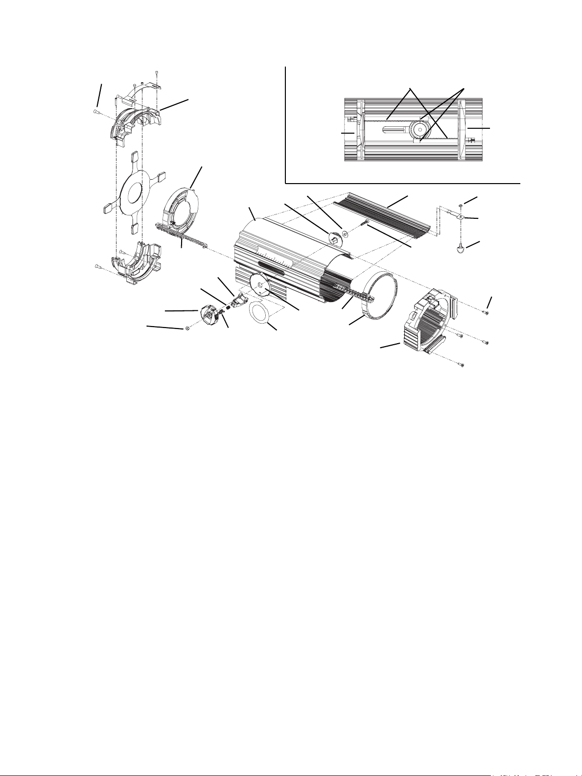
Assemble lens tube (15°-30° and 25°-50°)
Figure 21
Figure 20
Rear Lens
Aligned hash
marks
Gear teeth
Front
lens
Front barrel assembly
22
13
12
1
4
8
9
5
6
7
10
11
3
19
20
2
16
17
18
15
36
28
Tools Required:
• #2 Phillips head screwdriver
Step 1: Slide the front lens assembly (3) and rear lens assembly (4) into the lens tube (1)
as shown in Figure 20.
Step 2: Position the lens assembly gear teeth as shown in Figure 20.
Step 3: From inside the unit, place the gear spur (12) between the lens assemblies.
Make sure the vertical hash marks on the gear spur line up with the hash marks
on both the front and rear gear teeth. See Figure 20.
Step 4: Slide the light baffle (11) into the opening of the lens tube. See Figure 21.
Step 5: From inside the unit, pass the screw (15) through the washer (13), the hole on
the gear spur (12) and the light baffle (11).
Step 6: On the outside of the unit, place the adjustment dial (6) over the screw end (15)
and secure with the metal nut (5).
Step 7: Place the front barrel assembly onto the rear of the lens tube and secure with four
Step 8: With the extrusion door open, place the gel cap (19) on the front of the unit and
Step 9: Once the gel cap is in place, close the extrusion door and turn the fastener (18)
screws (22).
secure with four screws (20).
one-quarter turn clockwise to secure the baffle in place.
16 Source Four Zoom Assembly Guide
Page 19

Cleaning glass lens
WARNING:
Remove dust with a blast of oil-free air or wipe with a clean, lint-free cloth. Isopropyl alcohol,
distilled water or a 50%-50% mixture of each can be used to clean the glass surface.
Do not use ammonia-based or other harsh commercial cleaners. Clean lens
only as directed.
Commercially available glass cleaning agents should be avoided as they
may contain ammonia, other harsh chemical detergents or abrasive agents.
These cleaners may damage the glass surface and the Anti-Reflective
coatings. Do not immerse or soak the glass in any cleaning solution.
25°- 50° Lens Tube 17
Page 20

Corporate Headquarters
London, UK
Rome, IT
Unit 26-28, Victoria Industrial Estate, Victoria Road, London W3 6UU, UK Tel +44 (0)20 8896 1000 Fax +44 (0)20 8896 2000
Via Ennio Quirino Visconti, 11, 00193 Rome, Italy Tel +39 (06) 32 111 683 Fax +39 (06) 32 656 990
Holzkirchen, DE
3031 Pleasant View Road, P.O. Box 620979, Middleton, Wisconsin 53562-0979 USA Tel +608 831 4116 Fax +608 836 1736
Ohmstrasse 3, 83607 Holzkirchen, Germany Tel +49 (80 24) 47 00-0 Fax +49 (80 24) 47 00-3 00
Hong Kong Rm 1801, 18/F, Tower 1 Phase 1, Enterprise Square, 9 Sheung Yuet Road, Kowloon Bay, Kowloon, Hong Kong Tel +852 2799 1220 Fax +852 2799 9325
Service:
(Americas) [email protected]
Web:
www.etcconnect.com
7060M2550-06.01
Rev A Released 08/2007
Copyright © 2007 ETC. All Rights Reserved. Product information and specifications subject to change.
(UK) [email protected] (DE) [email protected]
(Asia) [email protected]
 Loading...