

Page 1
Source Four XT HID Zoom
15-30 and 25-50 Zoom
Installation Instructions
Unpacking
Remove the fixture from the carton and remove all packing materials. Remove the barrel to remove the
internal foam packing materials.
Removing and Installing the Barrel
WARN ING:
● Do not use this fixture with a damaged power lead. If the power lead (cordset)
is damaged, it must be replaced.
● Do not expose the interior of the fixture to moisture. Do not stand in water
while installing or servicing the fixture.
Failure to follow these warnings can result in serious injury or death.
CAUTION: Remove foam packing from internal lenses before connecting power
to the fixture.
Installation
WARN ING:
● Do not use this fixture if glass lens is deeply scratched or cracked. Damaged lenses must be
replaced.
● Do not mount the fixture on or near combustible surfaces.
Failure to follow these warnings can result in serious injury or death.
Install on a suitable, rigid permanent base with secured bolts. This can include poured concrete pads, factory-supplied
pole-top and wall-mount brackets, and other attachments which meet the published weight and wind-load requirements for
the fixture. For ground-mounting, reference the template and notes included on the reverse of these installation instructions.
● Weight: All weights are exclusive of accessories, color filters, and patterns.
15 -30: 39 pounds
25- 50: 34.5 pounds.
● Wind Load
15 -30: 1.4 square feet of effective projected area (EPA).
25- 50: 1.15 square feet of effective projected area (EPA).
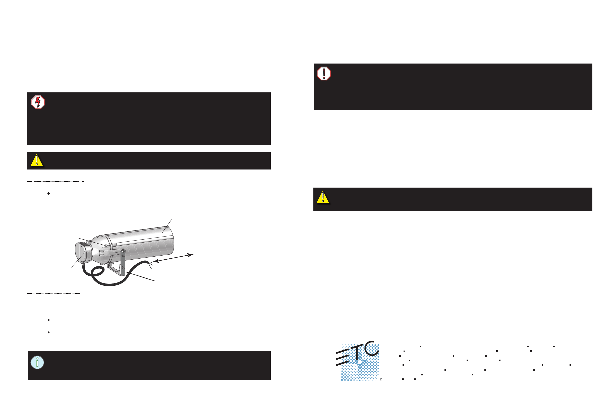
To remove the barrel:
Step 1: Loosen the three 4mm hex screws around the barrel.
There is a nylon retaining washer on each screw to prevent it from slipping out of the ballast
housing.
Step 2: Slide the barrel off the fixture.
Step 3: Hang the barrel on the yoke or set it safely aside.
4mm hex
screw (3)
Reflector
housing
Barrel
Remove or install barrel
Standard yoke
To install the barrel:
Step 1: Slide the barrel down over the lens rails, aligning the top ridges of the barrel with the top ridges of
the housing.
Step 2: Tighten the three 4mm hex screws around the barrel.
Partially tighten each screw, working progressively around the barrel until all have been
tight ened to 25in-lbs (2.82 Nm).
The nylon washer should be tightly sandwiched between the two flanges at each scew
connenction.
NOTE: Reference the Source Four XT HID Zoom User Manual for information
about lamp replacement, adjusting the light beam, and cleaning the fixture. The
User Manual is included in the carton and available for download at
www.etcconnect.com.
Page 1 of 2
Electrical
CAUTION: The fixture is sold for either 120V or 277V to match your power supply. Verify that
the lamp and ballast voltage requirements matches the power supply. Connecting the fixture to
the wrong voltage voids the warranty.
● The fixture must be installed by a qualified electrician.
● The fixture must be installed in accordance with national, state, and local electrical codes.
● The fixture must be grounded.
● An application-appropriate electrical junction box with cord grips are required.
● The junction box must not interfere with aiming or re-lamping the fixture.
● The fixture is completely pre-wired at the factory and there is no need for entry into the ballast housing.
● The lamp and ballast voltage must match the supply voltage.
● The fixture cannot be connected to a dimmer. Dimming will damage the ballast and void the warranty.
Lamp and Ballast Information
Acceptable voltage is either 120V or 220V - 277V (±10%) 50/60 Hz only, depending on the model purchased.
Refer to the User Manual for information about HID lamps.
● 120V (Nominal) Ballast:
- 120V ±10%, 60Hz
- 1.5 Amps operating current
● 220V, 230V (50Hz), 240V, 277V (Nominal) Ballast:
- 277V ±10%, 60Hz
- 220V, 230V, 240V ±10%, 50Hz/60Hz
- 0.61 Amps operating current at 277V
- 0.69 Amps operating current at 230V
Corporate Headquarters
London, UK
Rome, IT
Holzkirchen, DE
Hong Kong
Service:
Web:
7065M2100
Unit 26-28, Victoria Industrial Estate, Victoria Road, London W3 6UU, UK Tel +44 (0)20 8896 1000 Fax +44 (0)20 8896 2000
Via Pieve Torina, 48, 00156 Rome, Italy Tel +39 (06) 32 111 683 Fax +44 (0) 20 8752 8486
(Americas) service@etcconnect.com (UK) service@etceurope.com (DE) techserv-hoki@etcconnect.com (Asia) service@etcasia.com
www.etcconnect.com
3031 Pleasant View Road, P.O. Box 620979, Middleton, Wisconsin 53562-0979 USA Tel +608 831 4116 Fax +608 836 1736
Ohmstrasse 3, 83607 Holzkirchen, Germany Tel +49 (80 24) 47 00-0 Fax +49 (80 24) 47 00-3 00
Rm 1801, 18/F, Tower 1 Phase 1, Enterprise Square, 9 Sheung Yuet Road, Kowloon Bay, Kowloon, Hong Kong Tel +852 2799 1220 Fax +852 2799 9325
Copyright © 2013 ETC. All Rights Reserved. Product information and specifications subject to change.
Rev C Released 2013-10
Page 2
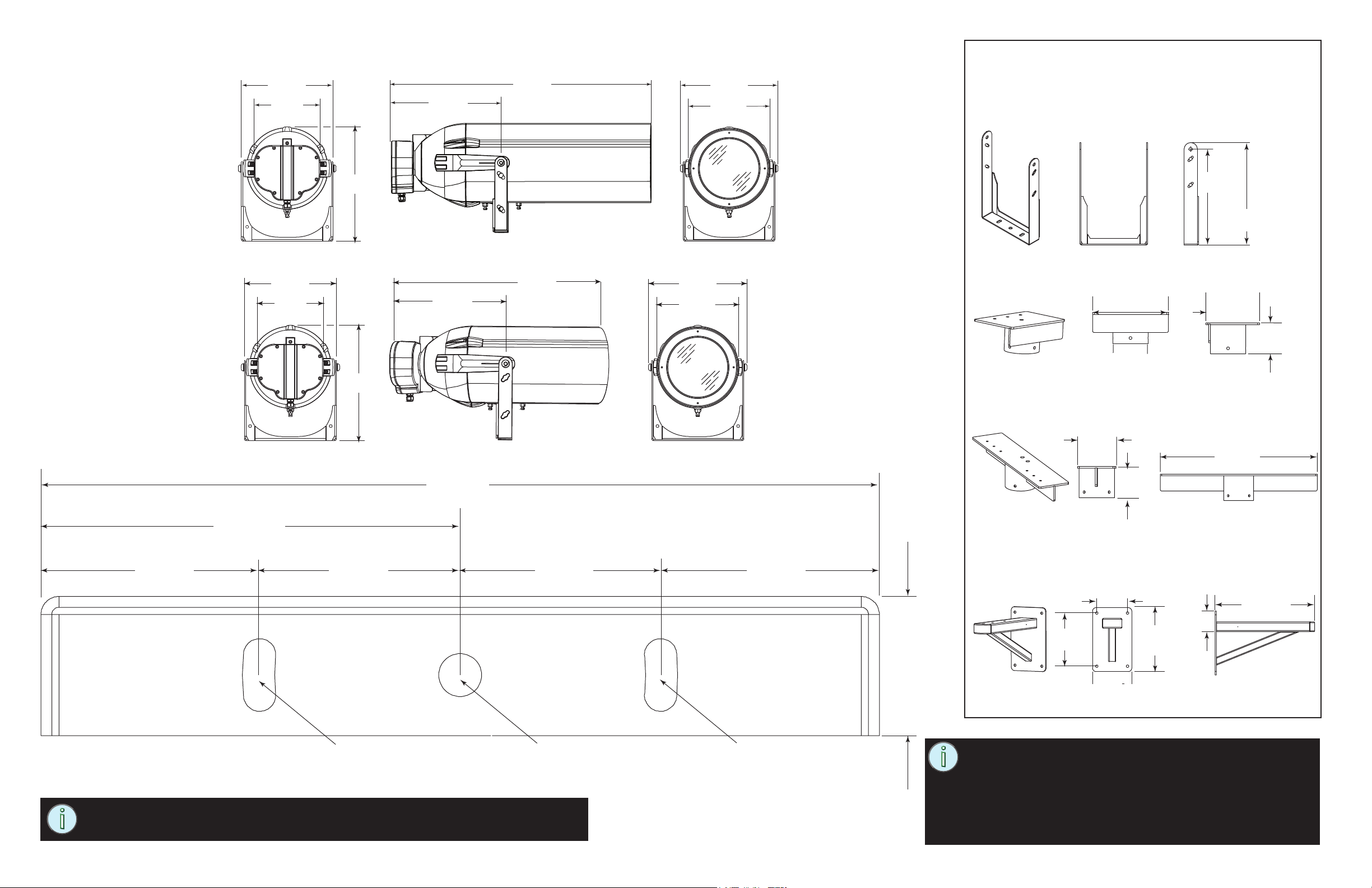
Fixture Dimensions
15-30
Rear view
10.4 inch
(264mm)
7.5 inch
(191mm)
13.11 inch
(333mm)
Side view
30.86 inch
(784mm)
Front view
11.1 inch
(282mm)
9.25 inch
(235mm)
Optional Mounting Adapters
Long Yoke
The mounting bolt pattern is the same as the standard yoke.
25-50
Mounting Template
5.2 inch
(132mm)
Rear view
10.4 inch
(264mm)
7.5 inch
(191mm)
13.0 inch
(330mm)
13.0 inch
(330mm)
13.11 inch
(333mm)
10.4 inch
(264mm)
Side view
24.42 inch
(620mm)
Front view
11.1 inch
(282mm)
9.25 inch
(235mm)
Single Pole Mount
10.25 inch
(260mm)
4.25 inch
(108mm)
(inside)
Twin Fixture Pole Top Mount
5.0 inch
(127mm)
4.1 inch
(104mm)
4.25 inch
(108mm)
(inside)
14.75 inch
(375mm)
15.75 inch
(400mm)
7.25 inch
(184mm)
4.1 inch
(104mm)
25.0 inch
(635mm)
2.7 inch
(68mm)
0.40 inch x 0.90 inch
(10mm x 23mm)
2.5 inch
(64mm)
2.5 inch
(64mm)
0.53 inch (13mm)
diameter hole
curved slot
NOTE: If printing this template from a PDF, it is important that you check the
dimensions to ensure the template is accurate.
0.40 inch x 0.90 inch
(10mm x 23mm)
curved slot
Page 2 of 2
2.7 inch
(68mm)
Wall or Square Pole Mount
1.7 inch (43mm)
NOTE: For ground mounting, use the full-sized template
shown here or download the template at www.etcconnect.com.
Use application appropriate bolts, nuts, and washers such as
hot-dipped zinc or stainless steel for wet locations.
Use only the center hole in the yoke if frequent aiming adjustments are needed. Use all three holes when the location is
fixed. The curved holes allow small aiming adjustments.
10.8 inch
(274mm)
6.25 inch
(159mm)
8.0 inch
(203mm)
13.0 inch
(330mm)
3.2 inch
(81mm)
20.25 inch
(514mm)
 Loading...