

Page 1

CE User Manual
Production Dates: September 2004 - Present
Copyright © 2008 Electronic Theatre Controls, Inc.
All Rights reserved.
Product information and specifications subject to change.
Part Number:
7061M1260-06.01
Released: June 2008
Picking# 7061M1009-B
Rev B
Page 2

Table of Contents
Declaration of conformity . . . . . . . . . . . . . . . . . . . . . . . . . . . . . . . . . .1
Source Four PARNel CE guidelines. . . . . . . . . . . . . . . . . . . . . . . . . .2
Basic assembly . . . . . . . . . . . . . . . . . . . . . . . . . . . . . . . . . . . . . . . . .3
Luminaire information . . . . . . . . . . . . . . . . . . . . . . . . . . . . . . . . .3
Colour frame holder . . . . . . . . . . . . . . . . . . . . . . . . . . . . . . . . . . .5
Replacing the HPL lamp . . . . . . . . . . . . . . . . . . . . . . . . . . . . . . .5
Focus knob positioning . . . . . . . . . . . . . . . . . . . . . . . . . . . . . . . .6
Lens identification . . . . . . . . . . . . . . . . . . . . . . . . . . . . . . . . . . . .7
Changing front lens . . . . . . . . . . . . . . . . . . . . . . . . . . . . . . . . . . .7
Cleaning glass lens . . . . . . . . . . . . . . . . . . . . . . . . . . . . . . . . . . .8
Cleaning the reflector. . . . . . . . . . . . . . . . . . . . . . . . . . . . . . . . . .8
Portable appliance test (PAT) guidelines. . . . . . . . . . . . . . . . . . .9
ETC®, Emphasis®, Expression®, Insight™, Imagine™, Focus™, Express™, Unison®, Obsession® II, ETCNet2™,
EDMX™, Source Four
of Electronic Theatre Controls, Inc. in the United States and other countries.
All other trademarks, both marked and not marked, are the property of their respective owners.
i Table of Contents
®
, Revolution®, Sensor®, and WYSILink™ are either registered trademarks or trademarks
Page 3

English
Declaration of conformity
We, Electronic Theatre Controls, Europe Ltd., declare under sole responsibility that the product:
Product name: Source Four PARNel CE
Product type/model: Source Four PARNel-EA
Lot: n/a
Batch/Serial number: n/a
Item numbers: one of each model
to which this declaration relates in conformity with the following standards:
EN60598-1:2000 Luminaires, General requirements and tests
EN60598-2-17:1990 Specification for luminaires for stage lighting, television, film, and
photographic studios (outside and indoor) - equiv. BS 4533-
102.17:1990
following the provisions of EU LV Directive(s) 73/23/EEC
London, United Kingdom
Mr. Adam Bennette
(Place of issue) (Name of authorised person)
(Date of issue) (signature of authorised person)
Electronic Theatre Controls Europe, Ltd. Registered office:
Unit 26-28, Victoria Industrial Estate, Grant Thornton House
Victoria Road, London W3 6UU U.K. Melton St., London NW1 28W, England
Telephone (+44) (0)20 896 1000 Registered in England No. 3057796
Fax (+44) (0)20 896 2000 VAT No. 6629487 90
1
Page 4

English
0.2m
Source Four PARNel CE guidelines
The Source Four PARNel CE is intended for professional use only. Read the entire User Guide
before using equipment.
WARNING:
• Do not mount the Source Four PARNel CE on or near a flammable surface.
• Use the Source Four PARNel CE in dry locations only, where humidity does not exceed 90 percent.
• The luminaire is for indoor use only and is not intended for outdoor use.
• For temporary installations, mount and support the Source Four PARNel CE only by the primary suspension yoke
holes. Suspend the luminaire from a hook clamp or a stand mount, using a securely tightened steel bolt (up to Ø
12 mm), flat washer and locking washer.
• In addition to primary suspension, attach a safety cable (ETC part #7060A1022) or chain to the secondary suspension point on the Source Four PARNel CE.
• If the external cable is damaged, it shall be replaced by ETC or our service agents.
• Always hang the Source Four PARNel CE with the colour frame held securely behind the retaining clip.
• Always replace the lamp if it becomes damaged or thermally deformed.
• Disconnect the unit from power before all cleaning and maintenance.
• The Source Four PARNel CE is suitable for indoor use with a maximum ambient temperature: T
• Maximum exterior surface temperature: T
• A multilingual label sheet is included with this manual. Affix the label of the appropriate language over the existing
warning label on the extension yoke. Do not cover ETC trademark or CE mark.
• The Source Four PARNel CE contains a CE safety screen that covers the lens to prevent injury from broken glass
die to lamp failure. Do not remove the safety screen.
• Keep the luminaire at least 2.7 meters away from any lit surface. Lighted objects at this distance or greater will not
exceed 90ºC temperature from projected light.
Please note the following safety precautions.
=242ºC
max
=45°C
a
2 Source FourPARNel CE User Manual
Page 5
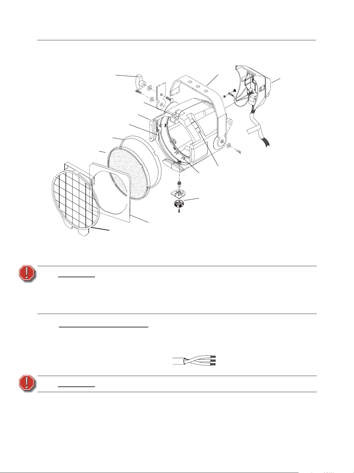
Basic assembly
WAR
NING
!
WAR
N
ING!
Figure 1
Yoke locking knob
Clear lens
Lamp housing
Yoke
Lens rotating ring
Color frame holder
Color frame
Lens catcher
Gel retaining clip
Tabs
Stippled lens
Focus knob
Safety screen
t 180 °c
English
Luminaire information
WARNING:
Wiring and power information
A plug of at least 2.5 amp (220/240V) rating should be attached to the luminaire’s mains lead. The
wires in the mains lead are 1.55mm
Green and Yellow: Earth
Blue: Neutral
Brown: Live
WARNING:
Current rating: 240V/2.5 amp maximum
Operating frequency: 50/60 Hz
Please note the following safety warnings before use:
Do not mount the luminaire on or near combustible surfaces.
Do not operate the luminaire without a lens installed.
Always hang the luminaire with the color frame retaining clip in the locked
position.
2
each and coloured in accordance with the following code:
This luminaire must be earthed.
3
Page 6
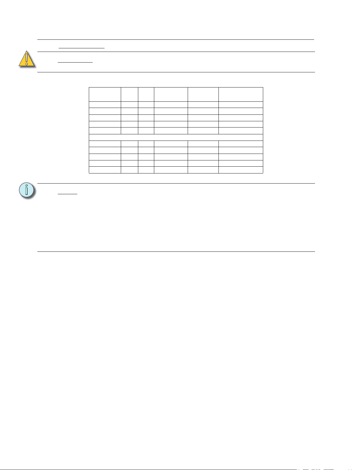
English
HPL lamp table
CAUTION:
Note:
Do not use lamps other than the HPL in Source Four fixtures. Use of lamps other
than HPL will void your warranty.
Lamp code Watts Volts Initial Lumen Colour
Average rated life
temp.
HPL 750/230 750 230 19,750 3,200°K 300 hours
HPL 750/230X 750 230 15,600 3,050°K 1500 hours
HPL 575/230 575 230 14,900 3,200°K 400 hours
HPL 575/230X 575 230 11,780 3,050°K 1500 hours
HPL 375/230 375 230 7,250 3,000°K 1000 hours
HPL 750/2240 750 240 19,750 3,200°K 300 hours
HPL 750/240X 750 240 15,600 3,050°K 1500 hours
HPL 575/240 575 240 14,900 3,050°K 400 hours
HPL 575/240X 575 240 11,780 3,050°K 1500 hours
HPL 375/240X 375 240 19,750 3,000°K 1000 hours
The performance of saturated colours may be less than desirable in any theatrical
lighting luminaire, especially when equipped with a 750w lamp. For best results,
always use high-quality colour media rated for high-temperature use.
ETC’s optional Gel Extender, part # PSF1029, will provide maximum colour media
life. The use of any gel extender accessory may limit the coverage of any wideangle lens or beam setting.
A variety of heat shield products is also available from many colour media
manufacturers. Follow the manufacturer’s instructions for the use of these
products.
4 Source FourPARNel CE User Manual
Page 7
English
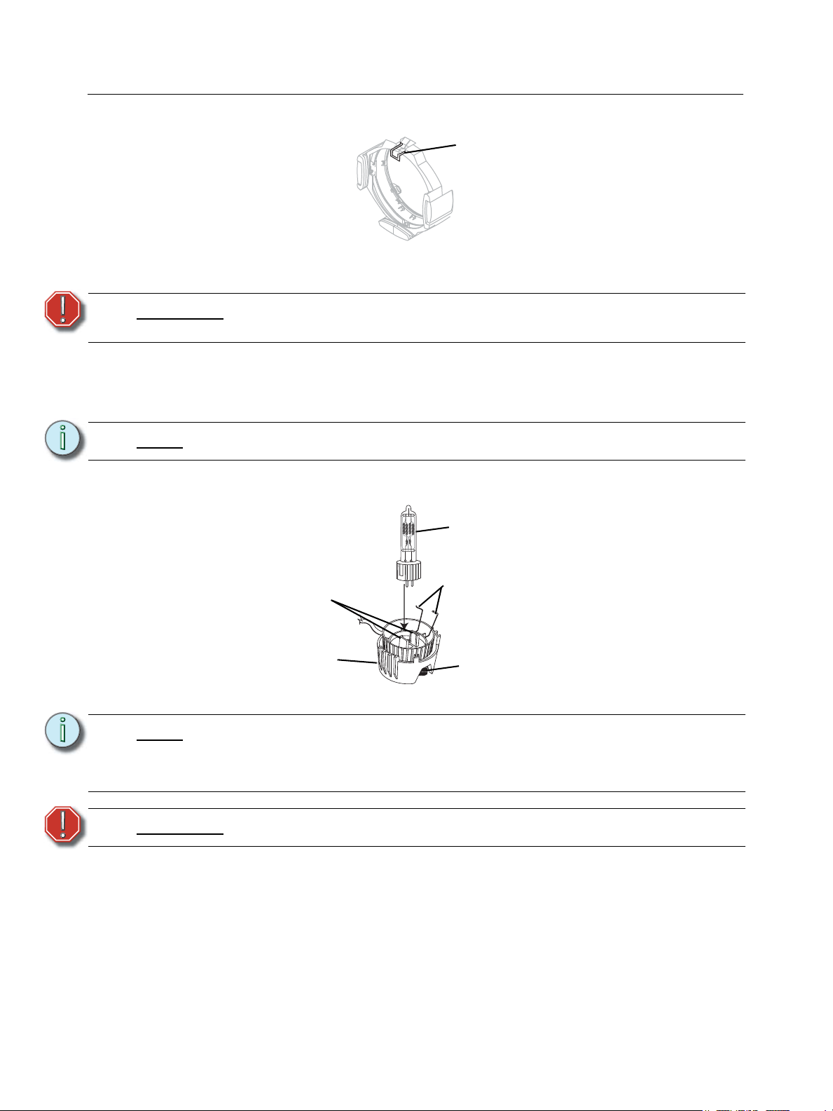
Figure 2
Retaining clip in the
locked position
HPL lamp
Lamp retention
brackets
Lamp housing
Figure 3
Knurled bolt
Lamp retaining clips
Colour frame holder
The colour frame holder is equipped with a spring-loaded retaining clip that prevents colour frames
and accessories from falling out. See Figure 2.
WARNING:
Step 1: Release the retaining clip by pushing it sideways while gently pulling backwards.
Step 2: Insert the colour frame.
Step 3: Lock the retaining clip by pushing sideways while gently pushing forward.
Note:
Make sure all colour frame accessories are locked in position with the
retaining clip before hanging the Source Four PARNel CE.
Use only colour frames or accessories with 19 cm mounting flange.
Replacing the HPL lamp
A lamp must be installed before you use the luminaire.
Note:
WARNING:
Step 1: Disconnect power to the Source Four PARNel CE before installing the lamp.
Step 2: Loosen the knurled bolt on the back of the lamp housing, disconnect the Earth continuity
cable and pull the housing out.
Verify that the HPL lamp you intend to install is suitable for your facility’s voltage;
115-, 120-, 230-, and 240-volt HPL lamps are available.
See HPL lamp table, page 4. Operating HPL lamps above their rated voltage
reduces lamp life and can cause premature lamp failure.
Let the lamp cool before replacing.
5
Page 8
English
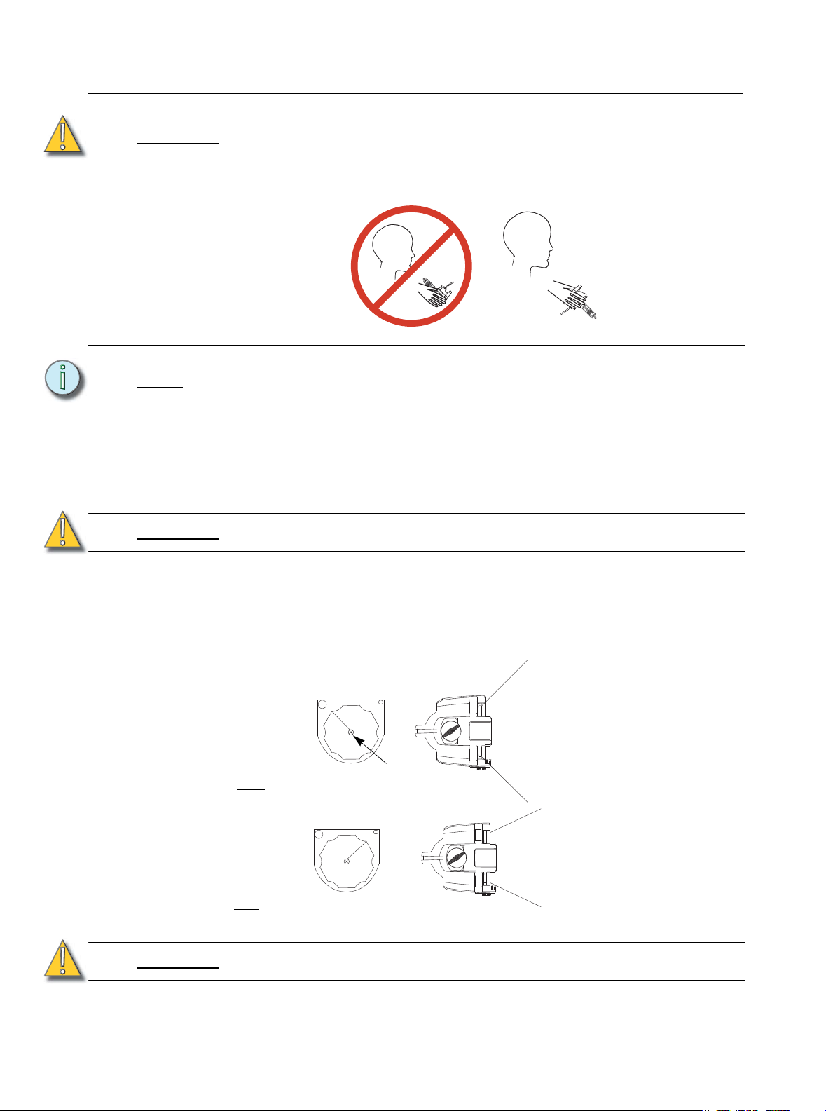
INCORRECT
CORRECT
Focus knob in
flood position
Figure 4
Focus knob in
spot
position
45° field angle
25° field angle
Focus knob
screw
Step 3: Holding by the base, remove the HPL lamp from its box.
CAUTION:
Note:
Step 4: Align the flat sides of the lamp base with the retention brackets on either side of the
socket as shown in Figure 3.
Step 5: Push down on the lamp base until the lamp seats firmly. When properly installed, the top
of the lamp’s base will be even with he top edges of the retention brackets.
CAUTION:
Use caution when installing or replacing any lamp.
When installing/replacing lamp, be sure to point the lamp away from your face and
away from others before inserting it firmly into the assembly.
This may prevent injuries if the lamp should break.
To avoid premature lamp failure, do not touch the lamp glass. If you do, clean it
carefully with isopropyl alcohol and a clean lint-free cloth. Allow to dry before
operation.
Improperly installed lamps cause premature lamp failure and socket problems.
Step 6: Press lamp retaining clip across lamp base to secure.
Step 7: Reconnect the Earth continuity cable. Reinstall the lamp housing by aligning the bolt hole
and tightening the knurled bolt.
Focus knob positioning
To adjust focus knob tension, loosen or tighten the focus knob screw. See Figure 4.
CAUTION:
Lens rotation knob does not rotate 360°. Do not attempt to exceed limit.
6 Source FourPARNel CE User Manual
Page 9
English
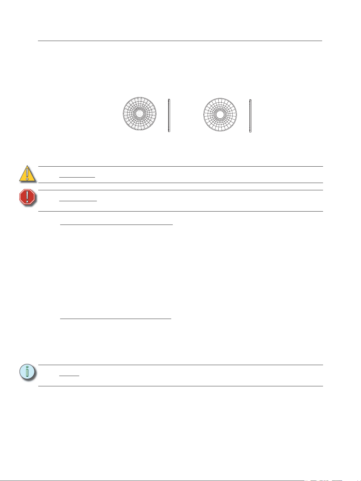
Figure 5
Wave/Stippled Lens (WS)
Wave/Clear Lens (WC)
Lens identification
Lenses for the Source Four PARNel come in two versions. The wave/clear lens is in a fixed position
in the rear of the luminaire. The wave/stippled lens is in the rotating ring at the front of the luminaire.
The wave surfaces face each other.
Changing front lens
Replace lens if it becomes cracked or badly scratched.
CAUTION:
WARNING:
Never operate the luminaire without a lens in place.
Unplug the luminaire and allow it to cool down before attempting to change
a lens.
Removing a wave/stippled front lens
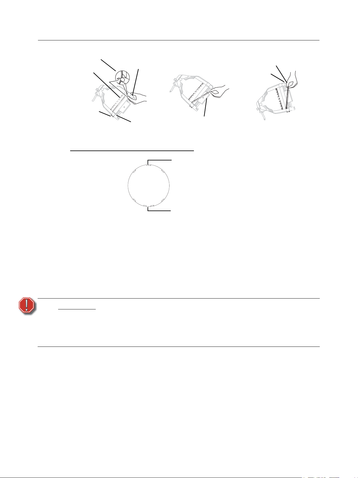
Step 1: Place the luminaire on a flat, stable work surface. Do Not remove or install lenses with
luminaire hanging.
Step 2: Rotate the focus knob to the full spot position.
Step 3: Tilt the front of the luminaire down at least 45°. See Figure 6.
Step 4: Press the spring clip with your finger to release the lens.
Step 5: Allow the lens to drop forward from under the clip.
Step 6: When the lens drops, remove your finger, allowing the lens to slide forward until it rests
on the lens catchers. See Figure 7.
Step 7: Carefully remove the lens.
Installing a wave/stippled front lens
Step 1: Position the luminaire with the front of the unit (lens side) facing you, and tilted slightly
upward. See Figure 8.
Step 2: Rotate the focus knob to the full spot position.
Step 3: Hold the lens by the edge and position it so the convex side faces the rear of the
luminaire.
Note:
Step 4: From the top of the luminaire, slide the lens behind the lens catchers and position it
behind the tabs on the bottom of the lens rotator ring.
Installing the front lens with the contoured side out will not impair the optics, but it
will make removing the lens difficult.
7
Page 10
English
Spring clip
Lens
Focus knob
Retaining clip
Tab
Lens catcher
Retaining clip
Spring clip
Figure 6
Figure 7
Figure 8
Top center notch
Bottom two center notches
Figure 9
Step 5: Gently push the top of the lens inward until it snaps behind the spring clip.
Positioning the wave/stippled front lens.
WARNING:
Step 1: There are seven notches cut into the stippled side of the lens. Position the lens
so the cluster of three notches is on top. The center notch of the cluster aligns
with the spring clip on the lens retainer ring. See Figure 9.
Step 2: The bottom of the lens has a cluster of four notches. Place the two center notches
behind the tabs at the bottom of the lens rotator ring.
Cleaning glass lens
Do not use ammonia-based or other harsh commercial cleaners. Clean lens
only as directed.
Commercially available glass cleaning agents should be avoided as they
may contain ammonia, other harsh chemical detergents or abrasive agents.
These cleaners may damage the glass surface and the Anti-Reflective
coatings. Do not immerse or soak the glass in any cleaning solution.
Replace lenses if they contain visible damage (cracks or deep scratches) that may impair their
effectiveness.
Remove dust with a blast of oil-free air or wipe with a clean, lint-free cloth. Isopropyl alcohol, distilled
water or a 50%-50% mixture of each can be used to clean the glass surface.
Cleaning the reflector
The reflector is located behind the rear, fixed position wave/clear lens and requires disassembly of
the luminaire to access it. See the Source Four ParNel Assembly Guide for instructions on luminaire
disassembly/assembly.
8 Source FourPARNel CE User Manual
Page 11
English
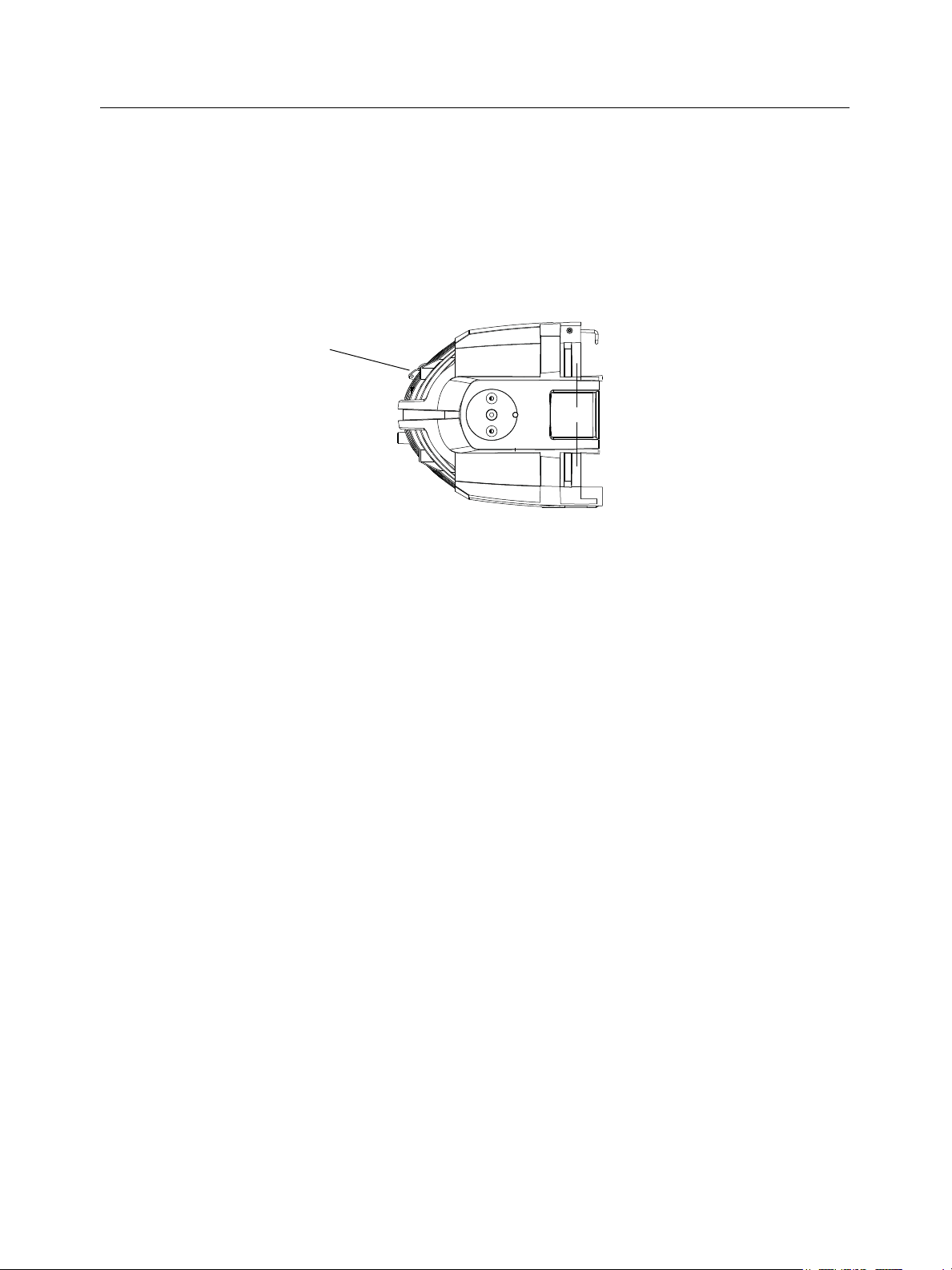
Figure 10
PAT connecting point
Portable appliance test (PAT) guidelines
The Portable Appliance Test is a set of tests that must be administered to electrical equipment in
the UK and some locations in Europe to ensure safety.The tests are typically carried out using a
small PAT device. The PAT device connects to a power source and then attaches to the product
via an electrical outlet and test probes. The PAT provides a simple pass or fail result, allowing rapid
testing of large inventories.
Source Four CE luminaires include a specific PAT point where the test clip is attached, as shown
in Figure 10. PAT tests should be performed by a qualified technician. Your local regulatory
authority has guidelines on the testing frequency.
9
Page 12

Corporate Headquarters
London, UK
Rome, IT
Unit 26-28, Victoria Industrial Estate, Victoria Road, London W3 6UU, UK Tel +44 (0)20 8896 1000 Fax +44 (0)20 8896 2000
Via Ennio Quirino Visconti, 11, 00193 Rome, Italy Tel +39 (06) 32 111 683 Fax +39 (06) 32 656 990
Holzkirchen, DE
3031 Pleasant View Road, P.O. Box 620979, Middleton, Wisconsin 53562-0979 USA Tel +608 831 4116 Fax +608 836 1736
Ohmstrasse 3, 83607 Holzkirchen, Germany Tel +49 (80 24) 47 00-0 Fax +49 (80 24) 47 00-3 00
Hong Kong Rm 1801, 18/F, Tower 1 Phase 1, Enterprise Square, 9 Sheung Yuet Road, Kowloon Bay, Kowloon, Hong Kong Tel +852 2799 1220 Fax +852 2799 9325
Service:
(Americas) [email protected]
Web:
www.etcconnect.com
7061M1260-06.01
Rev B Released 06/2008
Copyright © 2008 ETC. All Rights Reserved. Product information and specifications subject to change.
(UK) [email protected] (DE) [email protected]
(Asia) [email protected]
 Loading...