

Page 1

Express
24/48, 48/96, 72/144
Lighting control system
Version 3.03
Copyright 1999 Electronic Theatre Controls
Part Number: 4110M1006
Released: March 1999
Page 2

Page 3

Declaration of Conformity
Express two scene preset User Manual iii
Page 4

Limited warranty
Electronic Theatre Controls, Inc. (ETC) warrants
to the original owner or retail customer that for
a period of two years from date of delivery of a
portable system or energization of a
permanently installed system its products will
be free from defects in materials and
workmanship under normal use and service.
Warranty does not cover any product or part of
a product subject to accident, negligence,
alteration, abuse or misuse, or any accessories
or parts not supplied by ETC. Warranty does not
cover “consumable” parts such as fuses,
lamps, color media or components warranted
directly to the owner by the original
manufacturer. ETC’s warranty does not extend
to items not manufactured by us. Freight terms
on warranty repairs are FOB ETC factory or
designated repair facility. Collect shipments or
freight allowances will not be accepted.
ETC’s sole responsibility under this warranty
shall be to repair or replace at ETC’s option such
parts as shall be determined to be defective on
ETC’s inspection. ETC will not assume any
responsibility for any labor expended or
materials used to repair any equipment without
ETC’s prior written authorization. ETC shall not
be responsible for any incidental, general or
consequential damages, damages to property,
damages for loss of use, time, profits or
income, or any other damages.
The owner's obligations during the warranty
period under this warranty are to notify ETC at
ETC's address within one week of any
suspected defect, and to return the goods
prepaid to ETC at their factory or authorized
service center.
THIS WARRANTY IS CONTINGENT ON THE
CUSTOMER’S FULL AND TIMELY
COMPLIANCE WITH THE TERMS OF
PAYMENT SET FORTH IN THE “TERMS AND
CONDITIONS.” THIS WARRANTY IS
EXPRESSLY IN LIEU OF ANY AND ALL OTHER
WARRANTIES EXPRESSED OR IMPLIED,
INCLUDING THE WARRANTIES OF
MERCHANTABILITY AND FITNESS FOR A
PARTICULAR PURPOSE AND OF OTHER
OBLIGATIONS AND LIABILITIES ON OUR
PART. THE OWNER ACKNOWLEDGES THAT
NO OTHER REPRESENTATIONS WERE MADE
TO HIM OR RELIED UPON HIM WITH
RESPECT TO THE QUALITY AND FUNCTION
OF THE GOODS SOLD.
This written warranty is intended as a complete
and exclusive statement of the terms thereof.
Prior dealings or trade usage shall not be
relevant to modify, explain or vary this warranty.
Acceptance of, or acquiescing in, a course of
performance under this warranty shall not
modify the meaning of this agreement even
though either party has knowledge of the
performance and a chance to object.
Terms and Conditions
The following terms and conditions, and those
on the face hereof, shall control as to any order
accepted by Electronic Theatre Controls, Inc.
(ETC), notwithstanding any terms and
conditions that may be contained in any
purchase order or other document of Customer,
and ETC’s acceptance of any order is expressly
made conditional on Customer’s assent to such
terms and conditions. Such terms and
conditions will constitute the entire agreement
between the parties as to any order and will
supersede any prior understandings,
agreements, representations, or warranties.
Such terms and conditions will not be modified,
added to, superseded or otherwise altered
except by written document signed by an
authorized representative of ETC,
notwithstanding any terms and conditions
contained in the purchase order or other
document of Customer. ETC’s commencement
of performance and/or delivery shall not
constitute a waiver of such terms and
conditions or any acceptance of any terms and
conditions contained in the Customer’s order or
other documents. Acceptance of any product or
service by the Customer will be construed as
acceptance of ETC’s terms and conditions. Any
dispute or questions of construction with
respect to any order placed with ETC shall be
governed by the laws of the State of Wisconsin.
All prices are in US Dollars, FOB ETC’s factory
or warehouse. Prices, models and
specifications are subject to change without
notice. Orders must be in writing. Phone orders
will be accepted from established accounts
when followed by written confirmation. The
acceptance of any order does not imply
conformance with plans and specifications
unless the plans and specifications accompany
the order and are accepted as binding by ETC.
iv Limited warranty
Page 5

Equipment ordered which differs in any way
from our standard catalog items will require
drawings approved in writing by the Customer.
When drawings are approved, they shall take
precedence over all other written or verbal
instructions. Orders are effective only when
accepted and acknowledged by the factory.
Minimum order is $25.00 net, exclusive of
freight.
Price protection will be given on orders entered
for immediate shipment and for project orders
entered before the effective date of a price
increase. All other orders will be billed at price
at time of shipment. Quotations for custom
products are valid for thirty (30) days.
ETC shall not be liable for late delivery and/or
inability to perform due to unforeseen
circumstances or conditions, including our
ability to obtain supplies and raw materials,
government regulations, labor stoppages,
casualties, fire, and other causes beyond our
control. When such circumstances or
conditions have been remedied, ETC will make
and Customer will accept delivery/performance.
Equipment is shipped at the Customer’s risk
and our obligation to deliver equipment is
discharged upon their delivery in good condition
to the carrier. Shipments are FOB ETC factory
or warehouse. ETC prepay and bill freight on
UPS shipments. Freight and air are sent collect
unless specifically quoted otherwise. Unless
specifically prohibited, partial shipments will be
made. Federal, state and/or local taxes, duties
and other charges are the responsibility of the
purchaser.
If purchaser cancels any portion of a Purchase
Order prior to shipment, Purchaser shall be
liable to ETC for a cancellation charge equal to
ETC's actual costs incurred in connection with
that portion of the Purchase Order that is
cancelled, including, without limitation, labor
and materials.
Payment terms are net 30 days after date of
invoice. All payments are applied to the oldest
outstanding invoice. Accounts over thirty (30)
days are subject to a 1 1/2% (one and one-half
percent) per month late payment penalty. ETC
will have the option of withholding performance
under any and all orders from the Customer if an
invoice remains unpaid after 30 days. All
disputes otherwise unresolved between ETC
and Customer shall be resolved in a court of
competent jurisdiction for the location of ETC's
offices, Dane County, Wisconsin. If suit or
action is instituted by ETC to enforce payment
or performance by the Customer, the Customer
agrees to pay all costs and attorney's fees
incurred.
Claims for shortage or damaged must be made
within ten (10) days. Equipment is carefully
packed and delivered in good condition to the
carrier. All claims for loss or damage in transit
must be made by the consignee directly to the
carrier. ETC will render every aid and assistance
in the presentation and enforcement of such
claims without waiver of our rights to have
compliance with the terms of payment of our
invoices.
Equipment returned without ETC’s written
permission will not be accepted. Equipment
returned for credit must be in accordance with
established RMA procedures. Equipment must
be unused, in original cartons and in saleable
condition, subject to ETC’s quality control and
test inspection. Restocking charges of $25.00
or 25% (whichever is greater) plus any
repacking or reconditioning costs will be
deducted. Returns for warranty work will be via
warranty procedures. In no case will permission
be granted to return specially-modified or
custom equipment, or merchandise invoiced
more than six (6) months prior to date of
Customer’s return request.
Express two scene preset User Manual v
Page 6

Page 7

Table of Contents
Declaration of Conformity
Limited warranty
. . . . . . . . . . . . . . . . . . . . . . . . . . . . . . . . . . . . . . . . . . iv
. . . . . . . . . . . . . . . . . . . . . . . . . . . . . . . . . . . iii
Chapter 1
Introduction
Using this manual . . . . . . . . . . . . . . . . . . . . . . . . . . . . . . . . . . . . . . 2
Keyboard Help . . . . . . . . . . . . . . . . . . . . . . . . . . . . . . . . . . . . . . . . . 2
Text conventions . . . . . . . . . . . . . . . . . . . . . . . . . . . . . . . . . . . . . . . 2
Navigation and visual feedback . . . . . . . . . . . . . . . . . . . . . . . . . . . . 3
Output level conventions . . . . . . . . . . . . . . . . . . . . . . . . . . . . . . . . 4
Moving light concepts and terms . . . . . . . . . . . . . . . . . . . . . . . . . . 7
The Only command . . . . . . . . . . . . . . . . . . . . . . . . . . . . . . . . . . . . . 8
Using the trackpad . . . . . . . . . . . . . . . . . . . . . . . . . . . . . . . . . . . . . 9
Electronic backup maintenance . . . . . . . . . . . . . . . . . . . . . . . . . . . 10
Troubleshooting . . . . . . . . . . . . . . . . . . . . . . . . . . . . . . . . . . . . . . 10
How to reach ETC . . . . . . . . . . . . . . . . . . . . . . . . . . . . . . . . . . . . . 11
. . . . . . . . . . . . . . . . . . . . . . . . . . . . . . . . . . . . . . . . . . . . . . 1
Setting up the console . . . . . . . . . . . . . . . . . . . . . . . . . . . . . . . 2
New users . . . . . . . . . . . . . . . . . . . . . . . . . . . . . . . . . . . . . . . . 2
HTP channels . . . . . . . . . . . . . . . . . . . . . . . . . . . . . . . . . . . . . . 4
LTP Channels . . . . . . . . . . . . . . . . . . . . . . . . . . . . . . . . . . . . . . 4
Enabling LTP . . . . . . . . . . . . . . . . . . . . . . . . . . . . . . . . . . . . . . . 5
Working with LTP channels . . . . . . . . . . . . . . . . . . . . . . . . . . . 5
Fixtures . . . . . . . . . . . . . . . . . . . . . . . . . . . . . . . . . . . . . . . . . . . 7
Fixture attributes . . . . . . . . . . . . . . . . . . . . . . . . . . . . . . . . . . . . 7
Categories . . . . . . . . . . . . . . . . . . . . . . . . . . . . . . . . . . . . . . . . . 7
Personalities . . . . . . . . . . . . . . . . . . . . . . . . . . . . . . . . . . . . . . . 7
When working with fixtures . . . . . . . . . . . . . . . . . . . . . . . . . . . 8
When updating . . . . . . . . . . . . . . . . . . . . . . . . . . . . . . . . . . . . . 8
When recalling channels . . . . . . . . . . . . . . . . . . . . . . . . . . . . . . 8
Trackpad notes: . . . . . . . . . . . . . . . . . . . . . . . . . . . . . . . . . . . . 9
Sensitivity . . . . . . . . . . . . . . . . . . . . . . . . . . . . . . . . . . . . . . . . . 9
Chapter 2
Monitor displays
Colors in displays . . . . . . . . . . . . . . . . . . . . . . . . . . . . . . . . . . . . . . 14
Display features . . . . . . . . . . . . . . . . . . . . . . . . . . . . . . . . . . . . . . . 15
Flexichannel . . . . . . . . . . . . . . . . . . . . . . . . . . . . . . . . . . . . . . . . . 18
Patch . . . . . . . . . . . . . . . . . . . . . . . . . . . . . . . . . . . . . . . . . . . . . . . 19
Express two scene preset User Manual vii
. . . . . . . . . . . . . . . . . . . . . . . . . . . . . . . . . . . . . . . . . 13
Channel numbers/Standard patch . . . . . . . . . . . . . . . . . . . . . . 14
Channel numbers/Fixture patch . . . . . . . . . . . . . . . . . . . . . . . 14
Channel output levels . . . . . . . . . . . . . . . . . . . . . . . . . . . . . . . 14
Changing pages . . . . . . . . . . . . . . . . . . . . . . . . . . . . . . . . . . . 14
Stage . . . . . . . . . . . . . . . . . . . . . . . . . . . . . . . . . . . . . . . . . . . . 16
Blind . . . . . . . . . . . . . . . . . . . . . . . . . . . . . . . . . . . . . . . . . . . . 16
Fader . . . . . . . . . . . . . . . . . . . . . . . . . . . . . . . . . . . . . . . . . . . . 17
Updating Flexichannel . . . . . . . . . . . . . . . . . . . . . . . . . . . . . . . 18
Page 8

Chapter 3
System settings
Setting the number of dimmers . . . . . . . . . . . . . . . . . . . . . . . . . . 22
Setting the number of channels . . . . . . . . . . . . . . . . . . . . . . . . . . 23
Setting default fade times . . . . . . . . . . . . . . . . . . . . . . . . . . . . . . . 24
Setting default Level key . . . . . . . . . . . . . . . . . . . . . . . . . . . . . . . . 25
Setting default fader clear time . . . . . . . . . . . . . . . . . . . . . . . . . . . 25
Setting default sneak time . . . . . . . . . . . . . . . . . . . . . . . . . . . . . . 26
Enable / disable Blackout key . . . . . . . . . . . . . . . . . . . . . . . . . . . . 27
Enable / disable Flexichannel . . . . . . . . . . . . . . . . . . . . . . . . . . . . 27
Set grandmaster type . . . . . . . . . . . . . . . . . . . . . . . . . . . . . . . . . . 28
Set channels / submasters 1-to-1 . . . . . . . . . . . . . . . . . . . . . . . . . 28
Record lockout . . . . . . . . . . . . . . . . . . . . . . . . . . . . . . . . . . . . . . . 29
Enable / disable bump buttons . . . . . . . . . . . . . . . . . . . . . . . . . . . 29
Scene mode . . . . . . . . . . . . . . . . . . . . . . . . . . . . . . . . . . . . . . . . . 30
Setting the clock . . . . . . . . . . . . . . . . . . . . . . . . . . . . . . . . . . . . . . 31
Clock functions display . . . . . . . . . . . . . . . . . . . . . . . . . . . . . . 31
Daylight Savings Time . . . . . . . . . . . . . . . . . . . . . . . . . . . . . . 32
Set time/date . . . . . . . . . . . . . . . . . . . . . . . . . . . . . . . . . . . . . 32
12/24 hour clock . . . . . . . . . . . . . . . . . . . . . . . . . . . . . . . . . . . 32
Latitude, longitude, time zone . . . . . . . . . . . . . . . . . . . . . . . . 33
About Show . . . . . . . . . . . . . . . . . . . . . . . . . . . . . . . . . . . . . . . . . . 34
. . . . . . . . . . . . . . . . . . . . . . . . . . . . . . . . . . . . . . . . . . 21
Chapter 4
Patching channels
Selecting one-to-one patch . . . . . . . . . . . . . . . . . . . . . . . . . . . . . 36
Creating a custom patch . . . . . . . . . . . . . . . . . . . . . . . . . . . . . . . . 37
Proportional patching . . . . . . . . . . . . . . . . . . . . . . . . . . . . . . . . . . . 38
Unpatching individual dimmers . . . . . . . . . . . . . . . . . . . . . . . . . . . 39
Show labels . . . . . . . . . . . . . . . . . . . . . . . . . . . . . . . . . . . . . . . . . . 39
Dimmer profiles . . . . . . . . . . . . . . . . . . . . . . . . . . . . . . . . . . . . . . . 40
Pre-defined profiles . . . . . . . . . . . . . . . . . . . . . . . . . . . . . . . . . 40
Assigning a profile to a dimmer . . . . . . . . . . . . . . . . . . . . . . . 41
Profiles display . . . . . . . . . . . . . . . . . . . . . . . . . . . . . . . . . . . . 41
Creating or editing a profile . . . . . . . . . . . . . . . . . . . . . . . . . . . 42
Copying to another profile . . . . . . . . . . . . . . . . . . . . . . . . . . . 42
Clear All . . . . . . . . . . . . . . . . . . . . . . . . . . . . . . . . . . . . . . . . . . 43
Clear to End . . . . . . . . . . . . . . . . . . . . . . . . . . . . . . . . . . . . . . 43
Fill Between . . . . . . . . . . . . . . . . . . . . . . . . . . . . . . . . . . . . . . 43
Resetting a profile . . . . . . . . . . . . . . . . . . . . . . . . . . . . . . . . . . 43
Captured channels in Patch . . . . . . . . . . . . . . . . . . . . . . . . . . . . . . 44
Dimmer check . . . . . . . . . . . . . . . . . . . . . . . . . . . . . . . . . . . . . . . . 45
About Dimmer . . . . . . . . . . . . . . . . . . . . . . . . . . . . . . . . . . . . . . . . 46
About Dimmer with ETCLink . . . . . . . . . . . . . . . . . . . . . . . . . . . . . 47
Setting dimmers to Dimmer Doubling . . . . . . . . . . . . . . . . . . . . . 48
Patching to a Strand CD80 dimmer rack . . . . . . . . . . . . . . . . . . . . 49
. . . . . . . . . . . . . . . . . . . . . . . . . . . . . . . . . . . . . . . . 35
Chapter 5
Setting channel levels
Channel modes . . . . . . . . . . . . . . . . . . . . . . . . . . . . . . . . . . . . . . . 52
Selected channels . . . . . . . . . . . . . . . . . . . . . . . . . . . . . . . . . . 52
Captured channels . . . . . . . . . . . . . . . . . . . . . . . . . . . . . . . . . 52
Recorded channels . . . . . . . . . . . . . . . . . . . . . . . . . . . . . . . . . 52
Moving channels . . . . . . . . . . . . . . . . . . . . . . . . . . . . . . . . . . . 52
. . . . . . . . . . . . . . . . . . . . . . . . . . . . . . . . . . . . . 51
viii Table of Contents
Page 9

Tracked channels . . . . . . . . . . . . . . . . . . . . . . . . . . . . . . . . . . 52
Channel Attributes display . . . . . . . . . . . . . . . . . . . . . . . . . . . . . . . 53
Editing in the Channel Attributes display . . . . . . . . . . . . . . . . 54
Independent channels . . . . . . . . . . . . . . . . . . . . . . . . . . . . . . 54
Flipped channels . . . . . . . . . . . . . . . . . . . . . . . . . . . . . . . . . . . 54
Channel data type . . . . . . . . . . . . . . . . . . . . . . . . . . . . . . . . . . 55
Channel convention . . . . . . . . . . . . . . . . . . . . . . . . . . . . . . . . 55
Selecting channels . . . . . . . . . . . . . . . . . . . . . . . . . . . . . . . . . . . . 56
Selecting channels in Flexichannel mode . . . . . . . . . . . . . . . . . . . 56
Setting channel levels . . . . . . . . . . . . . . . . . . . . . . . . . . . . . . . . . . 57
Channel sliders . . . . . . . . . . . . . . . . . . . . . . . . . . . . . . . . . . . . 57
Trackpad . . . . . . . . . . . . . . . . . . . . . . . . . . . . . . . . . . . . . . . . . 57
Full . . . . . . . . . . . . . . . . . . . . . . . . . . . . . . . . . . . . . . . . . . . . . 57
Level key . . . . . . . . . . . . . . . . . . . . . . . . . . . . . . . . . . . . . . . . . 57
Flash . . . . . . . . . . . . . . . . . . . . . . . . . . . . . . . . . . . . . . . . . . . . 57
Sneak . . . . . . . . . . . . . . . . . . . . . . . . . . . . . . . . . . . . . . . . . . . . . . 58
Channel check . . . . . . . . . . . . . . . . . . . . . . . . . . . . . . . . . . . . . . . . 59
About Channel . . . . . . . . . . . . . . . . . . . . . . . . . . . . . . . . . . . . . . . . 60
Features of the display . . . . . . . . . . . . . . . . . . . . . . . . . . . . . . 60
Chapter 6
Adding moving lights to the show
Moving Light Functions menu . . . . . . . . . . . . . . . . . . . . . . . . . . . 64
Personality Setup . . . . . . . . . . . . . . . . . . . . . . . . . . . . . . . . . . . . . 65
Go to the Personality Setup display . . . . . . . . . . . . . . . . . . . . 65
Loading personalities into the console . . . . . . . . . . . . . . . . . . 66
Viewing a personality . . . . . . . . . . . . . . . . . . . . . . . . . . . . . . . 67
Deleting personalities . . . . . . . . . . . . . . . . . . . . . . . . . . . . . . . 67
Resetting defaults . . . . . . . . . . . . . . . . . . . . . . . . . . . . . . . . . . 67
Patching moving lights . . . . . . . . . . . . . . . . . . . . . . . . . . . . . . . . . 68
Go to the Fixture Patch display . . . . . . . . . . . . . . . . . . . . . . . . 68
Patching one fixture or a fixture range . . . . . . . . . . . . . . . . . . 69
Editing the fixture list . . . . . . . . . . . . . . . . . . . . . . . . . . . . . . . 70
Attribute Setup . . . . . . . . . . . . . . . . . . . . . . . . . . . . . . . . . . . . . . . 71
Go to the Attribute Setup display . . . . . . . . . . . . . . . . . . . . . . 72
Encoder Setup . . . . . . . . . . . . . . . . . . . . . . . . . . . . . . . . . . . . . . . . 73
Go to the Encoder Setup display . . . . . . . . . . . . . . . . . . . . . . 73
Changing assignments . . . . . . . . . . . . . . . . . . . . . . . . . . . . . . 74
Working with moving lights . . . . . . . . . . . . . . . . . . . . . . . . . . . . . . 75
Moving lights displays . . . . . . . . . . . . . . . . . . . . . . . . . . . . . . 75
Go to the Fixture Box window . . . . . . . . . . . . . . . . . . . . . . . . 75
Working with fixtures . . . . . . . . . . . . . . . . . . . . . . . . . . . . . . . 76
Setting levels in the Fixture Box . . . . . . . . . . . . . . . . . . . . . . . 77
Fixture focus with Solo . . . . . . . . . . . . . . . . . . . . . . . . . . . . . . 78
. . . . . . . . . . . . . . . . . . . . . . . . . . . . 63
Chapter 7
Cues
. . . . . . . . . . . . . . . . . . . . . . . . . . . . . . . . . . . . . . . . . . . . . . . . . . . 79
Cue types . . . . . . . . . . . . . . . . . . . . . . . . . . . . . . . . . . . . . . . . . . . 80
Recording functions . . . . . . . . . . . . . . . . . . . . . . . . . . . . . . . . . . . 81
Viewing cues . . . . . . . . . . . . . . . . . . . . . . . . . . . . . . . . . . . . . . . . . 81
Express two scene preset User Manual ix
Crossfade . . . . . . . . . . . . . . . . . . . . . . . . . . . . . . . . . . . . . . . . 80
Allfade . . . . . . . . . . . . . . . . . . . . . . . . . . . . . . . . . . . . . . . . . . . 80
Effect . . . . . . . . . . . . . . . . . . . . . . . . . . . . . . . . . . . . . . . . . . . 80
Blocking . . . . . . . . . . . . . . . . . . . . . . . . . . . . . . . . . . . . . . . . . 80
Subroutine . . . . . . . . . . . . . . . . . . . . . . . . . . . . . . . . . . . . . . . 80
Page 10

The oversized show . . . . . . . . . . . . . . . . . . . . . . . . . . . . . . . . . . . 82
Creating the oversized show . . . . . . . . . . . . . . . . . . . . . . . . . 82
Playing back an oversized show . . . . . . . . . . . . . . . . . . . . . . . 82
Working with cues in Stage . . . . . . . . . . . . . . . . . . . . . . . . . . . . . 83
Recording a cue in Stage . . . . . . . . . . . . . . . . . . . . . . . . . . . . . . . 83
Working with cues in Blind . . . . . . . . . . . . . . . . . . . . . . . . . . . . . . 84
Recording a cue in Blind . . . . . . . . . . . . . . . . . . . . . . . . . . . . . 84
Recording a cue with a single fade time . . . . . . . . . . . . . . . . . . . . 85
Recording a cue with split fade times . . . . . . . . . . . . . . . . . . . . . . 86
Recording a cue with a wait time . . . . . . . . . . . . . . . . . . . . . . . . . 87
Recording cues with Link and Follow . . . . . . . . . . . . . . . . . . . . . . 88
Link . . . . . . . . . . . . . . . . . . . . . . . . . . . . . . . . . . . . . . . . . . . . . 88
Follow . . . . . . . . . . . . . . . . . . . . . . . . . . . . . . . . . . . . . . . . . . . 89
Create playback loops with Link and Follow . . . . . . . . . . . . . . 90
Linking a macro to a cue . . . . . . . . . . . . . . . . . . . . . . . . . . . . . 91
Recording a cue using Solo . . . . . . . . . . . . . . . . . . . . . . . . . . . . . . 92
Labeling cues . . . . . . . . . . . . . . . . . . . . . . . . . . . . . . . . . . . . . . . . 93
Modifying a recorded cue live . . . . . . . . . . . . . . . . . . . . . . . . . . . . 94
Modifying channels in a cue . . . . . . . . . . . . . . . . . . . . . . . . . . 94
Modifying cue attributes . . . . . . . . . . . . . . . . . . . . . . . . . . . . . 95
Updating cues . . . . . . . . . . . . . . . . . . . . . . . . . . . . . . . . . . . . . 96
Using Update to modify fade rate . . . . . . . . . . . . . . . . . . . . . . . . . 98
Deleting cues . . . . . . . . . . . . . . . . . . . . . . . . . . . . . . . . . . . . . . . . 98
Copying cues . . . . . . . . . . . . . . . . . . . . . . . . . . . . . . . . . . . . . . . . . 99
Inserting cues . . . . . . . . . . . . . . . . . . . . . . . . . . . . . . . . . . . . . . . 100
Chapter 8
Track
. . . . . . . . . . . . . . . . . . . . . . . . . . . . . . . . . . . . . . . . . . . . . . . . . 101
Track record . . . . . . . . . . . . . . . . . . . . . . . . . . . . . . . . . . . . . . . . . 102
Using record to create tracks . . . . . . . . . . . . . . . . . . . . . . . . 102
Recording modified cues . . . . . . . . . . . . . . . . . . . . . . . . . . . 103
Inserting cues . . . . . . . . . . . . . . . . . . . . . . . . . . . . . . . . . . . . 105
Blackout cues and tracking . . . . . . . . . . . . . . . . . . . . . . . . . . 108
Chapter 9
Multipart cues
Recording a multipart cue . . . . . . . . . . . . . . . . . . . . . . . . . . . . . . 112
Converting a standard cue to a multipart cue . . . . . . . . . . . . . . . 113
Wait times in multipart cues . . . . . . . . . . . . . . . . . . . . . . . . . . . . 114
Editing a multipart cue . . . . . . . . . . . . . . . . . . . . . . . . . . . . . . . . . 115
. . . . . . . . . . . . . . . . . . . . . . . . . . . . . . . . . . . . . . . . . . 111
Deleting a part from a multipart cue . . . . . . . . . . . . . . . . . . . 115
Adding, deleting and modifying channels . . . . . . . . . . . . . . . 116
Using Update . . . . . . . . . . . . . . . . . . . . . . . . . . . . . . . . . . . . 116
Modifying fade and wait times . . . . . . . . . . . . . . . . . . . . . . . 117
Chapter 10
Playing back cues
Fader keys . . . . . . . . . . . . . . . . . . . . . . . . . . . . . . . . . . . . . . . . . . 121
Clear . . . . . . . . . . . . . . . . . . . . . . . . . . . . . . . . . . . . . . . . . . . 121
Go . . . . . . . . . . . . . . . . . . . . . . . . . . . . . . . . . . . . . . . . . . . . . 121
Hold . . . . . . . . . . . . . . . . . . . . . . . . . . . . . . . . . . . . . . . . . . . 121
Back . . . . . . . . . . . . . . . . . . . . . . . . . . . . . . . . . . . . . . . . . . . 121
Cue List . . . . . . . . . . . . . . . . . . . . . . . . . . . . . . . . . . . . . . . . . . . . 122
Fader Status display . . . . . . . . . . . . . . . . . . . . . . . . . . . . . . . . . . 123
Selecting cues . . . . . . . . . . . . . . . . . . . . . . . . . . . . . . . . . . . . . . . 123
. . . . . . . . . . . . . . . . . . . . . . . . . . . . . . . . . . . . . . . 119
x Table of Contents
Page 11

Playing a cue . . . . . . . . . . . . . . . . . . . . . . . . . . . . . . . . . . . . . . . . 124
Go to a different cue . . . . . . . . . . . . . . . . . . . . . . . . . . . . . . . . . . 124
Controlling fades manually . . . . . . . . . . . . . . . . . . . . . . . . . . . . . 125
Manual override . . . . . . . . . . . . . . . . . . . . . . . . . . . . . . . . . . 125
Rate override . . . . . . . . . . . . . . . . . . . . . . . . . . . . . . . . . . . . 126
Quickstep . . . . . . . . . . . . . . . . . . . . . . . . . . . . . . . . . . . . . . . . . . 127
Chapter 11
Groups
. . . . . . . . . . . . . . . . . . . . . . . . . . . . . . . . . . . . . . . . . . . . . . . . 129
Creating groups . . . . . . . . . . . . . . . . . . . . . . . . . . . . . . . . . . . . . . 130
Creating a group in Stage . . . . . . . . . . . . . . . . . . . . . . . . . . . 130
Creating a group from a look on stage . . . . . . . . . . . . . . . . . 130
Creating a group using Solo . . . . . . . . . . . . . . . . . . . . . . . . . 131
Working with groups in Blind . . . . . . . . . . . . . . . . . . . . . . . . . . . 132
Group mode . . . . . . . . . . . . . . . . . . . . . . . . . . . . . . . . . . . . . 132
Group Editing mode in Blind . . . . . . . . . . . . . . . . . . . . . . . . . 133
Working with groups in Stage . . . . . . . . . . . . . . . . . . . . . . . . . . . 134
Displaying a group . . . . . . . . . . . . . . . . . . . . . . . . . . . . . . . . 134
Modifying a group . . . . . . . . . . . . . . . . . . . . . . . . . . . . . . . . . 134
Updating groups . . . . . . . . . . . . . . . . . . . . . . . . . . . . . . . . . . 135
Labeling groups . . . . . . . . . . . . . . . . . . . . . . . . . . . . . . . . . . . . . . 137
Deleting groups . . . . . . . . . . . . . . . . . . . . . . . . . . . . . . . . . . . . . . 138
Copying groups . . . . . . . . . . . . . . . . . . . . . . . . . . . . . . . . . . . . . . 138
Using cues and submasters as groups . . . . . . . . . . . . . . . . . . . . 139
Modifying cues or submasters . . . . . . . . . . . . . . . . . . . . . . . . . . 140
Chapter 12
Focus points
Creating a focus point . . . . . . . . . . . . . . . . . . . . . . . . . . . . . . . . . 142
Working with focus points in Stage . . . . . . . . . . . . . . . . . . . . . . 144
Editing a focus point in Blind . . . . . . . . . . . . . . . . . . . . . . . . . . . . 147
Labeling focus points . . . . . . . . . . . . . . . . . . . . . . . . . . . . . . . . . 148
Deleting focus points . . . . . . . . . . . . . . . . . . . . . . . . . . . . . . . . . 149
Copying focus points . . . . . . . . . . . . . . . . . . . . . . . . . . . . . . . . . . 149
Setting levels with focus points . . . . . . . . . . . . . . . . . . . . . . . . . 150
. . . . . . . . . . . . . . . . . . . . . . . . . . . . . . . . . . . . . . . . . . . . 141
Creating a focus point in Stage . . . . . . . . . . . . . . . . . . . . . . . 142
Creating a focus point from a look on stage . . . . . . . . . . . . . 142
Creating a focus point using Solo . . . . . . . . . . . . . . . . . . . . . 143
Placing a focus point on stage . . . . . . . . . . . . . . . . . . . . . . . 144
Modifying a focus point . . . . . . . . . . . . . . . . . . . . . . . . . . . . 144
Updating focus points . . . . . . . . . . . . . . . . . . . . . . . . . . . . . . 145
Chapter 13
Submasters
Submaster types . . . . . . . . . . . . . . . . . . . . . . . . . . . . . . . . . . . . 152
Changing type . . . . . . . . . . . . . . . . . . . . . . . . . . . . . . . . . . . . . . 153
Submaster pages . . . . . . . . . . . . . . . . . . . . . . . . . . . . . . . . . . . . 154
Submaster bump buttons . . . . . . . . . . . . . . . . . . . . . . . . . . . . . . 155
Submaster LEDs . . . . . . . . . . . . . . . . . . . . . . . . . . . . . . . . . . . . . 156
Recording submasters . . . . . . . . . . . . . . . . . . . . . . . . . . . . . . . . 157
. . . . . . . . . . . . . . . . . . . . . . . . . . . . . . . . . . . . . . . . . . . . 151
Pile-on submaster . . . . . . . . . . . . . . . . . . . . . . . . . . . . . . . . . 152
Inhibitive submaster . . . . . . . . . . . . . . . . . . . . . . . . . . . . . . . 152
Effect submaster . . . . . . . . . . . . . . . . . . . . . . . . . . . . . . . . . 152
Bump button status . . . . . . . . . . . . . . . . . . . . . . . . . . . . . . . 155
Fade and dwell times for submasters . . . . . . . . . . . . . . . . . 157
Express two scene preset User Manual xi
Page 12

Adding a rate to a submaster . . . . . . . . . . . . . . . . . . . . . . . . 160
Specifying a submaster’s page . . . . . . . . . . . . . . . . . . . . . . . 161
Using Except to record a submaster . . . . . . . . . . . . . . . . . . 161
Inhibitive submasters . . . . . . . . . . . . . . . . . . . . . . . . . . . . . . . . . 162
Creating . . . . . . . . . . . . . . . . . . . . . . . . . . . . . . . . . . . . . . . . 162
Adding channels . . . . . . . . . . . . . . . . . . . . . . . . . . . . . . . . . . 163
Deleting channels . . . . . . . . . . . . . . . . . . . . . . . . . . . . . . . . . 163
Modifying submasters in Blind . . . . . . . . . . . . . . . . . . . . . . . . . . 164
Modifying submasters in Stage . . . . . . . . . . . . . . . . . . . . . . . . . . 164
Re-recording submasters . . . . . . . . . . . . . . . . . . . . . . . . . . . 164
Updating submasters . . . . . . . . . . . . . . . . . . . . . . . . . . . . . . 165
Live control of a submaster’s rate . . . . . . . . . . . . . . . . . . . . . . . . 167
Controlling submaster fades manually . . . . . . . . . . . . . . . . . . . . 167
Labeling submasters . . . . . . . . . . . . . . . . . . . . . . . . . . . . . . . . . . 168
Copying submasters . . . . . . . . . . . . . . . . . . . . . . . . . . . . . . . . . . 169
Loading cues or groups to submasters . . . . . . . . . . . . . . . . . . . . 169
Copying cues or groups to submasters . . . . . . . . . . . . . . . . . . . . 170
Clearing submasters . . . . . . . . . . . . . . . . . . . . . . . . . . . . . . . . . . 170
Chapter 14
Lists and spreadsheets
Cue List . . . . . . . . . . . . . . . . . . . . . . . . . . . . . . . . . . . . . . . . . . . . 172
Editing cues . . . . . . . . . . . . . . . . . . . . . . . . . . . . . . . . . . . . . 172
Submaster List . . . . . . . . . . . . . . . . . . . . . . . . . . . . . . . . . . . . . . 173
Editing submasters . . . . . . . . . . . . . . . . . . . . . . . . . . . . . . . . 174
Deleting submasters . . . . . . . . . . . . . . . . . . . . . . . . . . . . . . . 175
Group List . . . . . . . . . . . . . . . . . . . . . . . . . . . . . . . . . . . . . . . . . . 176
Labeling a group . . . . . . . . . . . . . . . . . . . . . . . . . . . . . . . . . . 176
Deleting a group . . . . . . . . . . . . . . . . . . . . . . . . . . . . . . . . . . 177
Focus Point List . . . . . . . . . . . . . . . . . . . . . . . . . . . . . . . . . . . . . . 177
Labeling a focus point . . . . . . . . . . . . . . . . . . . . . . . . . . . . . . 178
Deleting a focus point . . . . . . . . . . . . . . . . . . . . . . . . . . . . . . 178
Working in spreadsheets . . . . . . . . . . . . . . . . . . . . . . . . . . . . . . . 179
Cue spreadsheet . . . . . . . . . . . . . . . . . . . . . . . . . . . . . . . . . . 179
Submaster spreadsheet . . . . . . . . . . . . . . . . . . . . . . . . . . . . 182
Group spreadsheet . . . . . . . . . . . . . . . . . . . . . . . . . . . . . . . . 184
Focus point spreadsheet . . . . . . . . . . . . . . . . . . . . . . . . . . . . . . . 186
. . . . . . . . . . . . . . . . . . . . . . . . . . . . . . . . . . . . 171
Chapter 15
Park
. . . . . . . . . . . . . . . . . . . . . . . . . . . . . . . . . . . . . . . . . . . . . . . . . . 189
Using the Park display . . . . . . . . . . . . . . . . . . . . . . . . . . . . . . . . . 190
Parking dimmers . . . . . . . . . . . . . . . . . . . . . . . . . . . . . . . . . . . . . 190
Unparking dimmers . . . . . . . . . . . . . . . . . . . . . . . . . . . . . . . . . . . 191
Parking channels . . . . . . . . . . . . . . . . . . . . . . . . . . . . . . . . . . . . . 192
Unparking channels . . . . . . . . . . . . . . . . . . . . . . . . . . . . . . . . . . . 193
Parking recorded channels . . . . . . . . . . . . . . . . . . . . . . . . . . . . . 194
Unparking recorded channels . . . . . . . . . . . . . . . . . . . . . . . . . . . 194
Parking fixtures . . . . . . . . . . . . . . . . . . . . . . . . . . . . . . . . . . . . . . 195
xii Table of Contents
Unparking one dimmer . . . . . . . . . . . . . . . . . . . . . . . . . . . . . 191
Unparking all dimmers . . . . . . . . . . . . . . . . . . . . . . . . . . . . . 191
Using the keyboard . . . . . . . . . . . . . . . . . . . . . . . . . . . . . . . . 192
Parking at a focus point . . . . . . . . . . . . . . . . . . . . . . . . . . . . 192
Unparking one channel . . . . . . . . . . . . . . . . . . . . . . . . . . . . . 193
Unparking all channels . . . . . . . . . . . . . . . . . . . . . . . . . . . . . 193
After setting attribute levels from the keypad . . . . . . . . . . . 195
Page 13

After setting attribute levels at a focus point . . . . . . . . . . . . 195
Unparking fixtures . . . . . . . . . . . . . . . . . . . . . . . . . . . . . . . . . . . . 196
Chapter 16
Effects
. . . . . . . . . . . . . . . . . . . . . . . . . . . . . . . . . . . . . . . . . . . . . . . . 197
Blind Effects display . . . . . . . . . . . . . . . . . . . . . . . . . . . . . . . . . . 198
Features . . . . . . . . . . . . . . . . . . . . . . . . . . . . . . . . . . . . . . . . 198
Effects in Stage . . . . . . . . . . . . . . . . . . . . . . . . . . . . . . . . . . 199
Creating an effect in Blind . . . . . . . . . . . . . . . . . . . . . . . . . . . . . . 200
Notes on working with steps in Blind . . . . . . . . . . . . . . . . . . 201
Adding channels directly . . . . . . . . . . . . . . . . . . . . . . . . . . . . 201
Adding groups or focus points . . . . . . . . . . . . . . . . . . . . . . . 202
Adding grouped channels . . . . . . . . . . . . . . . . . . . . . . . . . . . 203
Creating an effect in Stage . . . . . . . . . . . . . . . . . . . . . . . . . . . . . 204
Notes on working with steps in Stage . . . . . . . . . . . . . . . . . 204
Adding channels directly . . . . . . . . . . . . . . . . . . . . . . . . . . . . 204
Adding groups or focus points . . . . . . . . . . . . . . . . . . . . . . . 205
Adding grouped channels . . . . . . . . . . . . . . . . . . . . . . . . . . . 206
Modifying the effect . . . . . . . . . . . . . . . . . . . . . . . . . . . . . . . . . . 207
Using Update . . . . . . . . . . . . . . . . . . . . . . . . . . . . . . . . . . . . 207
Editing channel levels . . . . . . . . . . . . . . . . . . . . . . . . . . . . . . 208
Adding channels . . . . . . . . . . . . . . . . . . . . . . . . . . . . . . . . . . 208
Deleting channels . . . . . . . . . . . . . . . . . . . . . . . . . . . . . . . . . 209
Inserting steps . . . . . . . . . . . . . . . . . . . . . . . . . . . . . . . . . . . 210
Deleting steps . . . . . . . . . . . . . . . . . . . . . . . . . . . . . . . . . . . . 211
Modifying effect attributes . . . . . . . . . . . . . . . . . . . . . . . . . . . . . 212
Modifying step timing and levels . . . . . . . . . . . . . . . . . . . . . . . . 213
Effect fade times . . . . . . . . . . . . . . . . . . . . . . . . . . . . . . . . . . . . . 214
Changing upfade, dwell and downfade . . . . . . . . . . . . . . . . 215
Changing upfade only . . . . . . . . . . . . . . . . . . . . . . . . . . . . . . 215
Changing downfade only . . . . . . . . . . . . . . . . . . . . . . . . . . . 215
Changing dwell only . . . . . . . . . . . . . . . . . . . . . . . . . . . . . . . 216
Resetting hold dwell time . . . . . . . . . . . . . . . . . . . . . . . . . . . 216
Setting a random effect rate . . . . . . . . . . . . . . . . . . . . . . . . . . . . 217
Running an effect cue . . . . . . . . . . . . . . . . . . . . . . . . . . . . . . . . . 217
Using an effect submaster . . . . . . . . . . . . . . . . . . . . . . . . . . . . . 217
Chapter 17
Subroutines
Steps . . . . . . . . . . . . . . . . . . . . . . . . . . . . . . . . . . . . . . . . . . . . . . 220
Cue steps . . . . . . . . . . . . . . . . . . . . . . . . . . . . . . . . . . . . . . . . . . 220
Style steps . . . . . . . . . . . . . . . . . . . . . . . . . . . . . . . . . . . . . . . . . . 221
Subroutine attributes . . . . . . . . . . . . . . . . . . . . . . . . . . . . . . . . . . 221
Creating subroutines . . . . . . . . . . . . . . . . . . . . . . . . . . . . . . . . . . 222
Editing a subroutine . . . . . . . . . . . . . . . . . . . . . . . . . . . . . . . . . . . 224
Deleting a step . . . . . . . . . . . . . . . . . . . . . . . . . . . . . . . . . . . . . . 224
Inserting a step . . . . . . . . . . . . . . . . . . . . . . . . . . . . . . . . . . . . . . 224
Chapter 18
Macros
Creating macros . . . . . . . . . . . . . . . . . . . . . . . . . . . . . . . . . . . . . 226
Express two scene preset User Manual xiii
. . . . . . . . . . . . . . . . . . . . . . . . . . . . . . . . . . . . . . . . . . . . 219
. . . . . . . . . . . . . . . . . . . . . . . . . . . . . . . . . . . . . . . . . . . . . . . . 225
Using Learn . . . . . . . . . . . . . . . . . . . . . . . . . . . . . . . . . . . . . . 226
Using Macro Editing . . . . . . . . . . . . . . . . . . . . . . . . . . . . . . . 228
Macro wait . . . . . . . . . . . . . . . . . . . . . . . . . . . . . . . . . . . . . . 229
Linking macros . . . . . . . . . . . . . . . . . . . . . . . . . . . . . . . . . . . 230
Page 14

Using submasters in macros . . . . . . . . . . . . . . . . . . . . . . . . 231
Playing macros . . . . . . . . . . . . . . . . . . . . . . . . . . . . . . . . . . . . . . 232
Canceling a macro . . . . . . . . . . . . . . . . . . . . . . . . . . . . . . . . 232
Powerup macro . . . . . . . . . . . . . . . . . . . . . . . . . . . . . . . . . . . . . . 232
Modifying macros . . . . . . . . . . . . . . . . . . . . . . . . . . . . . . . . . . . . 233
Clearing macros . . . . . . . . . . . . . . . . . . . . . . . . . . . . . . . . . . . . . . 233
Copying macros . . . . . . . . . . . . . . . . . . . . . . . . . . . . . . . . . . . . . 234
Sample macros . . . . . . . . . . . . . . . . . . . . . . . . . . . . . . . . . . . . . . 234
Chapter 19
Link lists
. . . . . . . . . . . . . . . . . . . . . . . . . . . . . . . . . . . . . . . . . . . . . . . 237
Link List overview . . . . . . . . . . . . . . . . . . . . . . . . . . . . . . . . . . . . 238
Setting up a link . . . . . . . . . . . . . . . . . . . . . . . . . . . . . . . . . . . . . . 239
Inserting a link . . . . . . . . . . . . . . . . . . . . . . . . . . . . . . . . . . . . . . . 240
Moving a link . . . . . . . . . . . . . . . . . . . . . . . . . . . . . . . . . . . . . . . . 241
Merging two links . . . . . . . . . . . . . . . . . . . . . . . . . . . . . . . . . . . . 241
Deleting a link . . . . . . . . . . . . . . . . . . . . . . . . . . . . . . . . . . . . . . . 242
Using a link . . . . . . . . . . . . . . . . . . . . . . . . . . . . . . . . . . . . . . . . . 242
Chapter 20
Diskette functions
Diskette management . . . . . . . . . . . . . . . . . . . . . . . . . . . . . . . . . 244
Formatting diskettes . . . . . . . . . . . . . . . . . . . . . . . . . . . . . . . . . . 244
Contents of the showfile . . . . . . . . . . . . . . . . . . . . . . . . . . . . . . . 245
Writing to diskette . . . . . . . . . . . . . . . . . . . . . . . . . . . . . . . . . . . . 245
Reading from diskette . . . . . . . . . . . . . . . . . . . . . . . . . . . . . . . . . 246
Read show and configuration . . . . . . . . . . . . . . . . . . . . . . . . 246
Read show components only . . . . . . . . . . . . . . . . . . . . . . . . 247
Read system configuration components only . . . . . . . . . . . 247
. . . . . . . . . . . . . . . . . . . . . . . . . . . . . . . . . . . . . . . 243
Chapter 21
Printing
. . . . . . . . . . . . . . . . . . . . . . . . . . . . . . . . . . . . . . . . . . . . . . . 249
Printer options . . . . . . . . . . . . . . . . . . . . . . . . . . . . . . . . . . . . . . . 250
Printing procedure . . . . . . . . . . . . . . . . . . . . . . . . . . . . . . . . . . . . 250
Printouts available . . . . . . . . . . . . . . . . . . . . . . . . . . . . . . . . . . . . 251
Moving lights . . . . . . . . . . . . . . . . . . . . . . . . . . . . . . . . . . . . 251
Chapter 22
Clear functions
Clear functions . . . . . . . . . . . . . . . . . . . . . . . . . . . . . . . . . . . . . . 254
Clear and reset procedure . . . . . . . . . . . . . . . . . . . . . . . . . . . . . . 254
Clear and reset options . . . . . . . . . . . . . . . . . . . . . . . . . . . . . . . . 255
. . . . . . . . . . . . . . . . . . . . . . . . . . . . . . . . . . . . . . . . . . 253
Chapter 23
Two scene preset
Enabling two scene mode . . . . . . . . . . . . . . . . . . . . . . . . . . . . . . 258
Express 24/48 . . . . . . . . . . . . . . . . . . . . . . . . . . . . . . . . . . . . 258
Express 48/96 and 72/144 . . . . . . . . . . . . . . . . . . . . . . . . . . 258
The two scene faders . . . . . . . . . . . . . . . . . . . . . . . . . . . . . . . . . 259
Two scene status display . . . . . . . . . . . . . . . . . . . . . . . . . . . . . . 260
Manual crossfades . . . . . . . . . . . . . . . . . . . . . . . . . . . . . . . . . . . 261
Flash a scene . . . . . . . . . . . . . . . . . . . . . . . . . . . . . . . . . . . . 261
Timed crossfades . . . . . . . . . . . . . . . . . . . . . . . . . . . . . . . . . . . . 262
Pause a timed crossfade . . . . . . . . . . . . . . . . . . . . . . . . . . . 262
. . . . . . . . . . . . . . . . . . . . . . . . . . . . . . . . . . . . . . . . 257
xiv Table of Contents
Page 15

Chapter 24
Dimmer monitoring
ETCLink functions . . . . . . . . . . . . . . . . . . . . . . . . . . . . . . . . . . . . 264
Enabling ETCLink . . . . . . . . . . . . . . . . . . . . . . . . . . . . . . . . . . . . 264
Error messages . . . . . . . . . . . . . . . . . . . . . . . . . . . . . . . . . . . . . . 265
How to enable / disable ETCLink error messages . . . . . . . . 266
ETCLink displays . . . . . . . . . . . . . . . . . . . . . . . . . . . . . . . . . . . . . 267
Dimming system status . . . . . . . . . . . . . . . . . . . . . . . . . . . . 267
Dimmer rack status . . . . . . . . . . . . . . . . . . . . . . . . . . . . . . . 268
Dimmer status . . . . . . . . . . . . . . . . . . . . . . . . . . . . . . . . . . . 269
Monitoring dimmers . . . . . . . . . . . . . . . . . . . . . . . . . . . . . . . . . . 270
Load Management display . . . . . . . . . . . . . . . . . . . . . . . . . . 270
Record Loads procedure . . . . . . . . . . . . . . . . . . . . . . . . . . . . . . . 271
Load Check procedure . . . . . . . . . . . . . . . . . . . . . . . . . . . . . 272
Clear Loads procedure . . . . . . . . . . . . . . . . . . . . . . . . . . . . . 273
Setting and unsetting dimmers . . . . . . . . . . . . . . . . . . . . . . . . . . 274
Setting a dimmer . . . . . . . . . . . . . . . . . . . . . . . . . . . . . . . . . 274
Unsetting a dimmer . . . . . . . . . . . . . . . . . . . . . . . . . . . . . . . 274
Working with Sensor backup looks . . . . . . . . . . . . . . . . . . . . . . . 275
Recording a backup look . . . . . . . . . . . . . . . . . . . . . . . . . . . . 275
Playing a backup look . . . . . . . . . . . . . . . . . . . . . . . . . . . . . . 276
. . . . . . . . . . . . . . . . . . . . . . . . . . . . . . . . . . . . . . 263
Chapter 25
Control interfaces
MIDI . . . . . . . . . . . . . . . . . . . . . . . . . . . . . . . . . . . . . . . . . . . . . . 278
ETC MIDI . . . . . . . . . . . . . . . . . . . . . . . . . . . . . . . . . . . . . . . 278
MIDI Show Control (MSC) . . . . . . . . . . . . . . . . . . . . . . . . . . 281
Real time programs . . . . . . . . . . . . . . . . . . . . . . . . . . . . . . . . . . . 284
Go to the Real Time Programs display . . . . . . . . . . . . . . . . . 284
Enabling / disabling real time programs . . . . . . . . . . . . . . . . 285
Creating real time programs . . . . . . . . . . . . . . . . . . . . . . . . . 286
Editing real time programs . . . . . . . . . . . . . . . . . . . . . . . . . . 288
Deleting real time programs . . . . . . . . . . . . . . . . . . . . . . . . . 288
Inserting real time programs . . . . . . . . . . . . . . . . . . . . . . . . . 288
Copying real time programs . . . . . . . . . . . . . . . . . . . . . . . . . 289
Moving real time programs . . . . . . . . . . . . . . . . . . . . . . . . . . 289
Sorting real time programs . . . . . . . . . . . . . . . . . . . . . . . . . . 289
Time Code . . . . . . . . . . . . . . . . . . . . . . . . . . . . . . . . . . . . . . . . . . 290
Creating time code programs . . . . . . . . . . . . . . . . . . . . . . . . 291
Reset loop time . . . . . . . . . . . . . . . . . . . . . . . . . . . . . . . . . . 294
Editing time code programs . . . . . . . . . . . . . . . . . . . . . . . . . 295
Deleting time code events . . . . . . . . . . . . . . . . . . . . . . . . . . 295
Inserting time code events . . . . . . . . . . . . . . . . . . . . . . . . . . 296
Copying time code events . . . . . . . . . . . . . . . . . . . . . . . . . . 297
Moving time code events . . . . . . . . . . . . . . . . . . . . . . . . . . . 298
Editing events . . . . . . . . . . . . . . . . . . . . . . . . . . . . . . . . . . . . 299
Setting time code frame rate . . . . . . . . . . . . . . . . . . . . . . . . 300
Running a time code program . . . . . . . . . . . . . . . . . . . . . . . 301
Remote macros . . . . . . . . . . . . . . . . . . . . . . . . . . . . . . . . . . . . . . 304
Remote trigger . . . . . . . . . . . . . . . . . . . . . . . . . . . . . . . . . . . . . . 305
. . . . . . . . . . . . . . . . . . . . . . . . . . . . . . . . . . . . . . . . 277
Express two scene preset User Manual xv
Page 16

Chapter 26
Accessories
Remote Focus Unit (RFU) . . . . . . . . . . . . . . . . . . . . . . . . . . . . . . 308
Alphanumeric keyboard . . . . . . . . . . . . . . . . . . . . . . . . . . . . . . . . 309
Console lights . . . . . . . . . . . . . . . . . . . . . . . . . . . . . . . . . . . . . . . 310
Expression Off-Line . . . . . . . . . . . . . . . . . . . . . . . . . . . . . . . . . . . 310
. . . . . . . . . . . . . . . . . . . . . . . . . . . . . . . . . . . . . . . . . . . . 307
Appendix A
Installation
Console’s back panel . . . . . . . . . . . . . . . . . . . . . . . . . . . . . . . . . 312
Installing the console and monitor . . . . . . . . . . . . . . . . . . . . . . . 313
Installing ETCNet . . . . . . . . . . . . . . . . . . . . . . . . . . . . . . . . . . . . . 314
Connecting dimmers to console . . . . . . . . . . . . . . . . . . . . . . . . . 315
Configuring DMX512 . . . . . . . . . . . . . . . . . . . . . . . . . . . . . . . . . . 316
Installing remote interfaces . . . . . . . . . . . . . . . . . . . . . . . . . . . . . 318
Installing an alphanumeric keyboard . . . . . . . . . . . . . . . . . . . . . . 323
Installing a printer . . . . . . . . . . . . . . . . . . . . . . . . . . . . . . . . . . . . 324
Installing Remote Focus Unit . . . . . . . . . . . . . . . . . . . . . . . . . . . 324
Installing MIDI . . . . . . . . . . . . . . . . . . . . . . . . . . . . . . . . . . . . . . . 325
Installing console lights . . . . . . . . . . . . . . . . . . . . . . . . . . . . . . . . 325
Installing remote macros . . . . . . . . . . . . . . . . . . . . . . . . . . . . . . . 326
Upgrading software . . . . . . . . . . . . . . . . . . . . . . . . . . . . . . . . . . . 328
. . . . . . . . . . . . . . . . . . . . . . . . . . . . . . . . . . . . . . . . . . . . . 311
External device fuse . . . . . . . . . . . . . . . . . . . . . . . . . . . . . . . 312
VGA monitor connections . . . . . . . . . . . . . . . . . . . . . . . . . . . 313
Port starting DMX512 numbers . . . . . . . . . . . . . . . . . . . . . . 316
Setting the port to Dimmer Doubling . . . . . . . . . . . . . . . . . . 317
Setting DMX512 speed . . . . . . . . . . . . . . . . . . . . . . . . . . . . 317
Installing jumpers . . . . . . . . . . . . . . . . . . . . . . . . . . . . . . . . . 318
Remote Interface Unit (RIU) . . . . . . . . . . . . . . . . . . . . . . . . . 318
Remote Video Interface (RVI) . . . . . . . . . . . . . . . . . . . . . . . . 320
Installing remote video monitors . . . . . . . . . . . . . . . . . . . . . 322
Wiring remote macros . . . . . . . . . . . . . . . . . . . . . . . . . . . . . 327
Console software upgrades . . . . . . . . . . . . . . . . . . . . . . . . . 328
Upgrading remote unit software . . . . . . . . . . . . . . . . . . . . . . 328
Appendix B
Error messages
Diskette error messages . . . . . . . . . . . . . . . . . . . . . . . . . . . . . . . 331
Other error messages . . . . . . . . . . . . . . . . . . . . . . . . . . . . . . . . . 331
ETCLink errors . . . . . . . . . . . . . . . . . . . . . . . . . . . . . . . . . . . . . . . 332
Fatal messages . . . . . . . . . . . . . . . . . . . . . . . . . . . . . . . . . . . 332
Secondary Messages . . . . . . . . . . . . . . . . . . . . . . . . . . . . . . 333
. . . . . . . . . . . . . . . . . . . . . . . . . . . . . . . . . . . . . . . . . . 331
Appendix C
Showfile
. . . . . . . . . . . . . . . . . . . . . . . . . . . . . . . . . . . . . . . . . . . . . . . 335
Show contents . . . . . . . . . . . . . . . . . . . . . . . . . . . . . . . . . . . . . . 335
Configuration contents . . . . . . . . . . . . . . . . . . . . . . . . . . . . . . . . 336
Appendix D
Softkeys
xvi Table of Contents
. . . . . . . . . . . . . . . . . . . . . . . . . . . . . . . . . . . . . . . . . . . . . . . 337
Stage . . . . . . . . . . . . . . . . . . . . . . . . . . . . . . . . . . . . . . . . . . . . . . 337
Stage . . . . . . . . . . . . . . . . . . . . . . . . . . . . . . . . . . . . . . . . . . . . . . 337
Blind/Cue . . . . . . . . . . . . . . . . . . . . . . . . . . . . . . . . . . . . . . . . . . . 337
Blind/Cue . . . . . . . . . . . . . . . . . . . . . . . . . . . . . . . . . . . . . . . . . . . 337
Page 17

Blind/Group . . . . . . . . . . . . . . . . . . . . . . . . . . . . . . . . . . . . . . . . . 338
Blind/Focus . . . . . . . . . . . . . . . . . . . . . . . . . . . . . . . . . . . . . . . . . 338
Blind/Submaster . . . . . . . . . . . . . . . . . . . . . . . . . . . . . . . . . . . . . 338
Blind/Submaster . . . . . . . . . . . . . . . . . . . . . . . . . . . . . . . . . . . . . 339
Blind/Cue/Effect . . . . . . . . . . . . . . . . . . . . . . . . . . . . . . . . . . . . . 339
Blind/(Cue or Sub)/Effect . . . . . . . . . . . . . . . . . . . . . . . . . . . . . . . 339
Blind/Submaster/Effect . . . . . . . . . . . . . . . . . . . . . . . . . . . . . . . . 339
Blind/Subroutine . . . . . . . . . . . . . . . . . . . . . . . . . . . . . . . . . . . . . 340
Stage/Fader . . . . . . . . . . . . . . . . . . . . . . . . . . . . . . . . . . . . . . . . . 340
Stage/Park . . . . . . . . . . . . . . . . . . . . . . . . . . . . . . . . . . . . . . . . . . 340
Patch . . . . . . . . . . . . . . . . . . . . . . . . . . . . . . . . . . . . . . . . . . . . . . 340
Setup - System Settings (1), Output Config (2) and Clear (4) . . . 341
Setup - Print (5) and Options (6) . . . . . . . . . . . . . . . . . . . . . . . . . 341
Setup - Macro Editing (8) . . . . . . . . . . . . . . . . . . . . . . . . . . . . . . . 341
Setup - ETC Link Functions (9) . . . . . . . . . . . . . . . . . . . . . . . . . . 341
Setup - ETC Link Functions (9) . . . . . . . . . . . . . . . . . . . . . . . . . . 342
Setup - Profiles (10), Channel Attributes (11) . . . . . . . . . . . . . . . 342
Setup - Real Time Programs (12) . . . . . . . . . . . . . . . . . . . . . . . . . 342
Setup - Time Code (13) . . . . . . . . . . . . . . . . . . . . . . . . . . . . . . . . 342
Setup - Moving Light Functions (15) . . . . . . . . . . . . . . . . . . . . . . 343
Setup - Moving Light Functions (15) . . . . . . . . . . . . . . . . . . . . . . 343
Appendix E
Time and location
United States . . . . . . . . . . . . . . . . . . . . . . . . . . . . . . . . . . . . . . . . 345
Outside the United States . . . . . . . . . . . . . . . . . . . . . . . . . . . . . . 346
. . . . . . . . . . . . . . . . . . . . . . . . . . . . . . . . . . . . . . . 345
Appendix F
Specifications
Index
. . . . . . . . . . . . . . . . . . . . . . . . . . . . . . . . . . . . . . . . . . . . . . . . . 353
. . . . . . . . . . . . . . . . . . . . . . . . . . . . . . . . . . . . . . . . . . . 347
Express two scene preset User Manual xvii
Page 18

xviii Table of Contents
Page 19

Chapter 1
Introduction
This manual covers the installation and operation of lighting systems
containing ETC’s Express 24/48, Express 48/96 and Express 72/144
control consoles operating with version 3.03 system software. The
differences between these consoles is shown under
Specifications
referred to as Express unless a distinction is necessary.
Chapter one includes information to orient you to the console and the
manual
• Using this manual
• Using Help
• Text conventions
• Navigation and visual feedback
• Output level conventions
• Moving light concepts and terms
• The Only command
• Using the trackpad
• Electronic backup maintenance
• Troubleshooting
, page 347. Throughout the manual, all three consoles are
.
It includes the following sections:
Appendix F
Express two scene preset User Manual 1
Page 20

Using this manual
This manual provides instructions for using the console’s features and
optional accessories.
Setting up the console
If you are setting up the system for the first time, see
Installation
information about setting up your system. If the system is already in place,
you may not need to refer to these chapters.
, page 311, and
New users
If you are new to lighting systems or to ETC’s consoles, read chapters 4
through 13 for instructions about patching conventional lights and moving
light fixtures, setting levels and using cues, groups, and submasters.
These are the building blocks for creating and running any show. Once you
are comfortable with these functions, chapters 16 through 19 provide
more advanced information on effects, subroutines, macros and link lists.
Keyboard Help
Chapter 3 System settings
Appendix A
, page 21, for
Help screens are available for all console keys, including softkeys and
wheels
console.
.
To display help screens, press [Help], then press any key on the
Text conventions
In this manual, console keys and softkeys are indicated by square
brackets, such as [Enter] and [S1]
display are printed in boldface, such as Select channel
other sections of the manual are printed in italics, such as
Introduction
.
.
Messages appearing on a console
.
References to
Chapter 1
2 Chapter 1 Introduction
Page 21
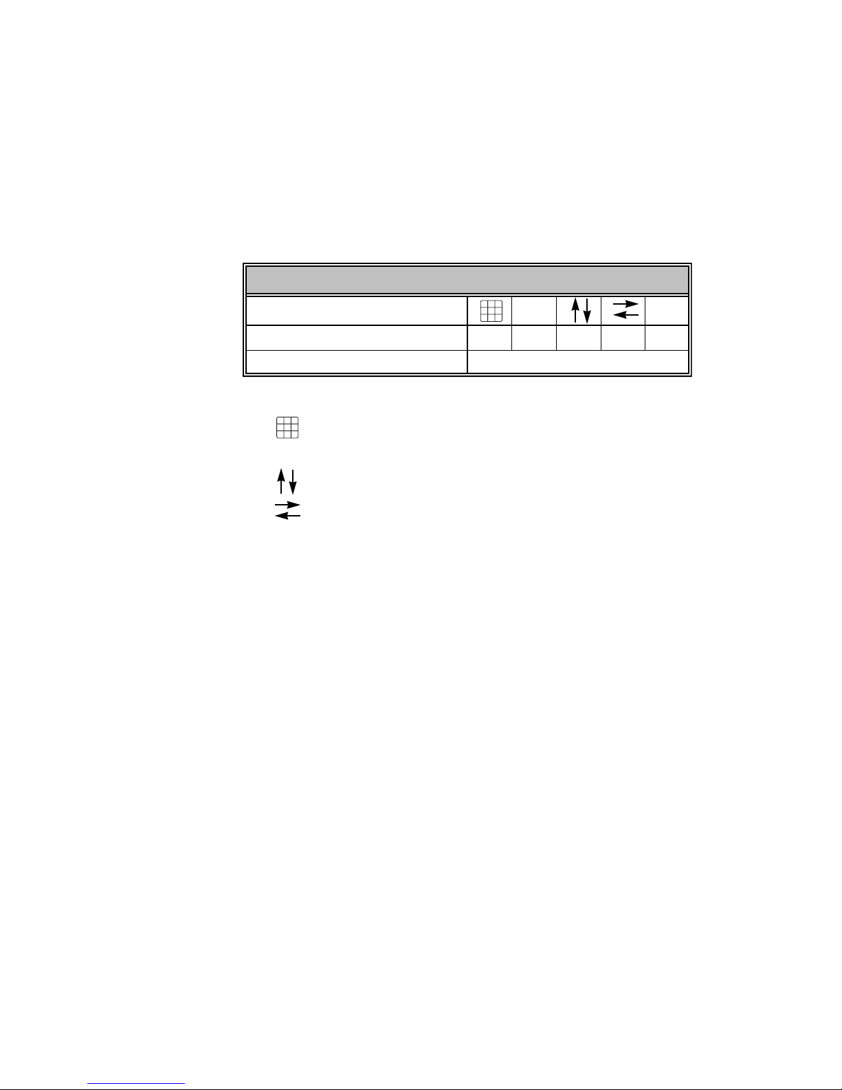
Navigation and visual feedback
Move through console menus and displays in the ways that work best for
you. The console offers alternative navigational techniques and visual
feedback that confirms your choices all along the way.
Note how navigation and feedback information is collected in the table
below. Tables like this are used throughout this User Manual to help you
use console displays. When alternative navigational techniques perform
the same function, examples in the text illustrate the technique that many
find the most convenient or efficient to use.
Navigation and Feedback - Console menus
7
1
Select a menu item XXX
Highlighted characters Item selected
In these Navigation and Feedback tables,
9
8
7
564
represents the keypad,
23
1
represents the softkeys,
[S]
9
8
564
[S] ±
23
represent the up and down keyboard arrows,
represent the right and left keyboard arrows, and
±
represent the plus and minus keys.
Express two scene preset User Manual 3
Page 22

Output level conventions
The console uses both a highest level, or pile-on, convention and a last
action convention to determine levels for channels affected by more than
one control
HTP channels
The behavior of a pile-on channel is defined by the Highest Takes
Precedence (HTP) rule. The console reads all output levels it receives for
an HTP channel and sets that channel to the highest of them
controlled by a submaster always obeys the HTP rule, but the Blackout
key, Grandmaster control and parked channels all have priority over levels
set from the keypad.
.
Channels may be defined to operate with either convention.
.
A channel
For example, if an HTP channel is included in both a submaster
that has played back and is in a fader, the console sets the channel at the
higher of the two levels. Or, you may use the keypad to select that
channel and set it to any level, regardless of the levels set either by the
cue or the submaster.
HTP channels in the console are called “normal” channels.
LTP Channels
Channels may also be defined in the console to follow the Latest Takes
Precedence (LTP) rule. An LTP channel obeys the latest command to set
its level. When the command is to fade to a level, an LTP channel can fade
either in a physical fader (in the foreground) or in a background fader. Each
LTP channel has its own background fader.
An LTP channel fades in the foreground if its level moves to a new level
in the next cue. When a channel is fading in the foreground and no change
in that channel is commanded by the next cue, the fade continues in the
background. A cue stops running in the background when the last of its
channels stops fading in the background. Up to 600 cues may run in the
background at once.
For example, consider three cues recorded for channels Chan 1, Chan 2
and Chan 3, all of which are set as LTP channels. The cues contain
percentage levels for these three channels as follows:
• When Cue 1 starts, channel Chan 1 starts fading to level 25 with Cue
1 timing.
• If Cue 2 starts before Cue 1 ends, channel Chan 1 continues fading in
the background with Cue 1 timing and channel Chan 2 starts fading in
the foreground to level 50 with Cue 2 timing.
• If Cue 3 starts before Cue 2 ends, channels Chan 1 and Chan 3 start
fading in the foreground to level 50 with Cue 3 timing; channel Chan
2 continues fading in the background with Cue 2 timing.
Chan 1 Chan 2 Chan 3
Cue 1 25 0 0
Cue 2 25 50 0
Cue 3 50 50 50
and a cue
4 Chapter 1 Introduction
Page 23

Enabling LTP
You can set a channel’s status to LTP or HTP as long as the channel is not
used in Fixture Patch. If the channel is patched to a fixture, the personality
controls the HTP/LTP status. All attributes (channels) are set to LTP by a
personality except the intensity attribute. All channels not patched to a
fixture default to HTP (considered “normal”).
Set channels to HTP or LTP, either singly or in ranges, in the Channel
Attributes display using the following procedures.
Keystrokes:
1. Press [Setup] [1][1] [Enter].
2. Press [1] [Thru] [1][0]
[Enter].
3. Press [ → ] [ → ] [ → ] [ →].
4. Press [1].
Working with LTP channels
Background overrides
Cues running in the background can be stopped, adjusted or otherwise
controlled with background overrides.
shown in the table below.
Background Override Operations
1. Clear Cue(s)
2. Cancel Cue(s)
3. Finish Cue(s)
4. Master Cue(s)
on X-Wheel
5. Alter Rate of Cue(s)
on X-Wheel
Action:
Selects the channel attributes display
Specifies channels 1 through 10
Move to LTP field
Sets channels to LTP
1
There are five override options, as
Clears cue levels.
Stops the fade or effect.
Takes cue channels to their completed
levels immediately.
Takes proportional control of cue
levels immediately.
Adjusts cue timing.
Control background overrides as follows:
Keystrokes: Action:
1. Press [Stage] [S3],
Background Overrides.
2. Press [5] [Enter].
3. Press [#] [Enter].
a. Press [0] in this step to apply an override operation to all cues.
1.
Identify which cue contains a particular channel from the About
Channel display, covered under About Channel, page 60.
Express two scene preset User Manual 5
Selects the Background Overrides list
a
Specifies cue 5
Specifies the override operation you
want performed
Page 24

Effects
LTP channels may be used to preserve an effect in certain channels
regardless of levels in the effect. Also, multiple effects can run
simultaneously, and other looks can be provided concurrently with
effects.
These features are available in the console when you use LTP channels.
When an effect cue is sandwiched between two other cues, LTP channel
levels in the effect cue are ignored when determining which control takes
precedence. A cue that runs after an effect skips over the previous effect
cue to determine what happens to levels. If there is a move in the current
cue with respect to the same channel in the cue before the effect, the
channel fades in the current cue and is “stolen” from the effect. If no
move, the channel continues in the effect.
Blocking cue
A cue running in the background ends when its last fading channel has
finished or a background override ends the cue prematurely. Sometimes,
however, you would like to end a background cue prematurely.
The way to do that is to follow the background cue with a blocking cue.
A blocking cue does to timing what an allfade cue does to level. As soon
as an allfade cue is started, all unused channels are forced to zero.
Similarly, when a blocking cue starts, all channels running in background
cues are faded to completion in the blocking cue’s timing. A blocking cue
ends all background cues.
Aside from its initial effect on background cues, the blocking cue runs
from that point on just like any other cue, including the possibility that it
could be forced to the background itself by the next cue.
6 Chapter 1 Introduction
Page 25

Moving light concepts and terms
Fixtures
Conventional lights, sometimes called fixtures, are single attribute
devices whose intensity can be controlled by a console connected to a
dimmer. In this User Manual, however, the term
refer to multi-attribute devices such as moving lights to distinguish them
from conventional lights. The programming methods in this manual apply
to any multi-attribute device controlled by DMX512 as to moving lights.
Fixture attributes
Every fixture has a set of attributes that you use to control it. For instance,
a basic moving light might have only three attributes: intensity, pan and
tilt. You control the fixture’s brightness by adjusting the level of a DMX512
channel that controls a dimmer assigned to the fixture. Similarly, you
control the fixture’s horizontal and vertical movements by adjusting the
levels of DMX512 channels assigned to the fixture’s pan and tilt
attributes. This simple fixture would require three channels to fully control
it. Other, more complicated fixtures could have additional attributes such
as color, focus or gobo, and each additional attribute would require an
additional DMX512 channel to control it.
In contrast, a standard ellipsoidal spotlight needs only one DMX512
channel to fully control it, namely the one that controls the dimmer
assigned to the spotlight. Only the spotlight’s intensity can be controlled
by changing the channel level. It has no other attributes.
fixture
is often used to
Categories
Most attributes can be naturally categorized as affecting the beam, the
image, the color or the position. All attributes are initially assigned to one
of these four categories or to a fifth one called None. Beam attributes
include Intensity, Zoom, Focus, Iris, and Frost. Image attributes include
Gobo and F/X. Color attributes include Color, Cyan, Magenta, and Yellow.
Position attributes include Pan and Tilt. You can customize the
assignment of attributes to categories, including assigning an attribute to
multiple categories and assigning as many attributes as you want to a
single category.
Personalities
Every fixture has an electronic personality that describes how it can be
controlled. The personality specifies the attributes for the fixture and the
order in which these attributes are presented to DMX512 channels.
Assigning a personality to a fixture makes channel patching quick and
easy. All you need to do is define which console channels and DMX512
addresses are first—the personality directs the rest of the assignment.
Many personalities are included with the console software. Other
personalities for leading moving light fixtures on the market are being
developed by ETC. As additional personalities become available, these are
made available to dealers and placed on the ETC website for downloading.
Also available from dealers and at the website is a program called the
Expression Personality Editor which enables you to create and edit
fixture personalities on an IBM-compatible computer. For further
information about these options, call ETC Technical Services at
800-775-4382 or visit the ETC website at www.etcconnect.com.
Express two scene preset User Manual 7
Page 26

The Only command
Only is a particularly powerful console command. Use Only to restrict a
selection while programming or creating a look on stage.
When working with fixtures
Use Only to restrict the selection of fixture attributes by category, such as
when you are creating or modifying a cue, submaster, group or focus
point. For example, press [S8], Fixture, [8] [S4], Only, [Position] to place
the pan and tilt attributes on the trackpad.
When updating
Following is a list of things you can select when using Only after the
Update command in Stage. If you make selections and change your mind,
press [Channel] [0] to reselect all non-zero channels.
Channels...................... Example: Press [S4], Only, [Channel] [1] [Thru]
Fixtures........................ Example: Press [S4], Only, [S8], Fixture, [1]
Fixture attributes........ Example: Pressing [S8], Fixture, [1] [S4], Only,
Fixture categories....... Example: Pressing [S8], Fixture, [1] [S4], Only,
Cues ............................. Example: Pressing [S4], Only, [Cue] [5] selects all
Submasters ................ Example: Pressing [S4], Only, [Sub] [6] selects all
Groups ......................... Example: Pressing [S4], Only, [Group] [7] selects
Focus Points................ Example: Pressing [S4], Only, [Focus Point] [8]
[5].
[And] [2].
[S6], Attribute, [6] selects attribute 6 of fixture 1.
[Beam] selects all attributes in the Beam category for fixture 1.
channels in cue 5 (not for effect cues).
channels in submaster 6 (not for effect
submasters).
all channels in Group 7.
selects all channels in Focus Point 8.
When recalling channels
Use to restrict a selection from among the channels, fixtures and
attributes on stage.
The use of Only after the Update command is illustrated with the
following examples:
• Press [Group] [1] [S4], Only, [Channel] [5] [Thru] [1][0] to select channels in group 1 that lie in the range 5 through 10.
• Press [Group] [1] [S4], Only, [Cue] [6] to select channels in Group 1
that are also in cue 6.
8 Chapter 1 Introduction
Page 27

Using the trackpad
Use the Express trackpad to set rates and levels. The trackpad operates
in three modes, single mode, double mode, and XY mode, described
below. You can also set the trackpad’s sensitivity.
Most of the time the trackpad is in single mode. If the
Single
mode
Double
mode
XY
mode
console prompts you for a rate or a level, moving your
finger up on the trackpad increases the rate or level.
Moving it down decreases the rate or level.
If you use the Link List function to link two or more
channels and then select any linked channel, the
trackpad automatically switches into double mode. In
double mode the trackpad is divided into two regions,
The left side controls channels in the X half of the link
(colored gold on the display). The right side controls
channels in the Y half of the link (colored yellow on the
display). Move your finger up or down on either side to
control channel levels in the corresponding link.
If you use the Link List function to link two or more
channels and set the link’s position attribute for XY
position, then select any linked channel with that
attribute, the trackpad automatically switches into XY
mode. In XY mode move your finger right or left on the
trackpad to control channels in the X half of the link
(colored gold on the display). Move your finger up or
down to control channels in the Y half of the link (colored
yellow on the display).
Trackpad notes:
• If you have channels selected from both kinds of link, the trackpad
defaults to double mode.
• In double mode you may only set one side at a time.
Sensitivity
To the left of the trackpad you will find two buttons that control trackpad
sensitivity. The top button has a rough texture. Press this to set the
trackpad for low sensitivity. The lower button has a smooth texture. Press
this to set the trackpad for high sensitivity. Use high sensitivity for precise
level or rate adjustments. Use low sensitivity for faster, less precise
adjustments.
Express two scene preset User Manual 9
Page 28

Electronic backup maintenance
Information in console memory is preserved by an electronic backup
system for approximately 28 days. Within the limits of this system, if
power should fail or if you shut down and then re-power, all programmed
elements should be the same as they were. For additional security, ETC
recommends that you routinely save to diskette as you go along and
before shutting down.
CAUTION
recharged periodically to function as intended. You must have the
processor on for at least seven hours every 28 days to maintain the
necessary charge.
: The electronic backup maintenance system must be
Troubleshooting
If you have problems using your console, please refer to this manual’s
index or to the console’s Help2 function for additional information.
If you do not find the answer in the manual, please call your local dealer
or ETC Technical Services. Have the following information available before
you call:
• Console model and serial number (located on back panel)
• Software version (displayed in the lower right corner of the Setup
menu)
• Options installed
• Dimmer installation type
• Dimmer manufacturer
2.
See Keyboard Help, page 2.
10 Chapter 1 Introduction
Page 29

How to reach ETC
To reach the ETC Technical Services department, call one of the numbers
shown below. After hours and weekend calls are answered electronically
and forwarded to a service representative. You can also reach ETC in the
United States via email using the address given below.
United States
Electronic Theatre Controls, Inc.
Technical Services Department
3030 Laura Lane
Middleton, WI 53562
Monday through Friday, 8:00 AM to 6:00 PM CST
800-775-4382
(608) 831-4116
Email: service@etcconnect.com
Europe
ETC Europe Ltd.
Technical Services Department
5 Victoria Industrial Estate
Victoria Road,
London W3 6UU England
(+44) 181 896 2000
Asia
ETC Asia, Ltd.
Technical Services Department
Room 605-606
Tower III, Enterprise Square
9 Sheung Yuet Road
Kowloon Bay, Kowloon, Hong Kong
(+852) 2799 1220
Express two scene preset User Manual 11
Page 30

12 Chapter 1 Introduction
Page 31

Chapter 2
Monitor displays
Express operates with one color video monitor. This monitor provides
information regarding your show, including a cue list, the current status of
the console’s two fader pairs and a variety of user selectable displays.
These displays allow you to create and run shows and to configure your
console and your lighting system.
If your system includes ETCNet, additional monitors may be installed at
other locations, such as backstage or in the sound booth. These remote
monitors show the same displays as the console’s monitor. To install
remote monitors, see
Chapter two includes descriptions of the following displays:
• Stage
• Blind
• Flexichannel
• Patch
Installing remote video monitors
, page 322.
Express two scene preset User Manual 13
Page 32

Colors in displays
The colors in which channel numbers and output levels are displayed on
screen provide information about the channels. The following list shows
the meaning of colors in Stage and Blind displays.
Channel numbers/Standard patch
Gray........................Unselected channel.
White......................Channel not selected by Only function.
Yellow....................Selected channel. Controlled by the level (Y) wheel.
Channel numbers/Fixture patch
Gray bar.................Surrounds all channels of one fixture.
Light gray ..............Low channels for 16-bit data types.
Gold .......................Channels linked through the link list or fixtures.
Yellow ...................Selected channels of selected fixtures.3
Channel output levels
White on Red.........Channel level when it is being changed.
Yellow....................In Stage, a channel in yellow was set by a submaster.
White......................In Stage, a channel in white was set by an effect. In
Blind, a channel in white was set by a submaster,
group, focus point or an allfade cue.
Gray........................Channel was recorded into a multipart cue, but not in
the currently displayed part (Blind only).
Red .........................In Stage, captured channels are in red. In Blind,
channels not recorded are in red.
Green .....................Channel output level is changed from what it was in
the previous cue. In Blind only, channel output is
lower than it was in the previous cue.
Purple.....................Channel output level is the same as it was in the
previous cue (tracking).
Blue ........................In Blind only, channel output level is higher than it
was in the previous cue.
3
Changing pages
Channels are displayed on several pages in the Stage and Blind displays.
Use [S4], Previous Page, and [S5], Next Page, to switch from page to
page. Also, pressing [←] takes you to the first page, pressing [↑] takes you
to the previous page (last page if currently on the first page), pressing [↓]
takes you to the next page, and pressing [→] takes you to the final page.
3.
Only High channels for 16-bit data types.
14 Chapter 2 Monitor displays
Page 33

Display features
Three of the console displays—Stage, Blind and Patch—share many
features, such as a channel display area, command line and softkeys. This
chapter’s illustrations of these displays are all labeled with these common
features, and the explanations are given directly below. If some common
features differ slightly for a particular illustration, such as the profile
assignment in Patch, that information and other unique information for the
display is given with the illustration.
Display name
Identifies the display shown and the current time.
Keypad corner
Indicates how the console will interpret the next number entered from the
keypad. For example, when the Keypad corner displays “Chan” the next
number you press will be taken as a channel number. If you enter a range,
such as with the [Thru], [And] or [Except] keys, each number is displayed
in turn but only the last number in the range remains.
Channel area
Shows channels, their levels and focus point references, if any, in
selected cues, submasters, groups or focus points. Below each channel
number is its level, if set. Below each level is the reference to the focus
point, if any, used to set the level.
Prompt area
Shows a prompt or information display related to your next or justcompleted action.
Attribute bar
Shows current settings for the selection, such as a cue, group or
submaster.
Softkeys
Shows additional functions available by pressing console keys [S1]
through [S8].
Express two scene preset User Manual 15
Page 34

Stage
The Stage display shows you the current levels of all active channels. Up
to 100 channels appear on the display at a time.
Global
settings
Channel
area
Fader Status
Attribute bar
Softkeys
Display name
Keypad corner
Cue /
Time Code
List
Global settings
Current settings for Grandmaster, Blackout and submaster page.
Fader Status
Shows current status of both fader pairs, including which cues are
running, their fade times, percentage of completion and follow time.
Cue / Time Code List
Normally, this displays a cue list, but it can be toggled to show a Time
Code list. The Cue List shows all cues along with their attributes. The last
cue that ran in the faders is highlighted in yellow, and the next cue in
sequence is highlighted in white (can be changed from Stage mode, but
not from Blind). The Time Code List is a comprehensive listing of all time
code events in the show. See
information.
To toggle between the lists:
1. Press [Setup].
2. Choose 6 - Option Settings from the Setup menu, then press [Enter].
3. Choose 7 - Display Cue/Time Code List from the Option Settings
menu, then press [Enter].
4. Follow prompt to toggle the display.
Blind
The Blind display lets you work on cues, groups and submasters without
affecting the look on stage. It looks exactly like the Stage display, pictured
above, except some of the softkeys are different4 and it has Blind for the
Display Name.
4.
See Appendix D Softkeys, page 337 for a complete tabulation of
console softkeys.
Time Code
, page 290, for further
16 Chapter 2 Monitor displays
Page 35

Fader
Express has a special Fader display that allows you to isolate channels in
the display according to whether they come from the A/B or C/D fader
pairs. You may also separately display channels in background faders.
Enter the Fader display from the Stage display as follows:
1. Press [S7], More Softkeys, until Fader appears at softkey S4.
2. Press [S4], Fader.
Upon entering the Fader display, you are prompted to select a display
from the four options listed below. You can re-select the display at any
time by pressing [S1], Select Fader.
1. A/B Fader
2. C/D Fader
3. Both Faders
4. Background Channels
Express two scene preset User Manual 17
Page 36

Flexichannel
When you enable Flexichannel,5 only channels used somewhere in the
show will appear on the display screens, subject to the following rules:
• Flexichannel displays channels whose levels are set, whether
recorded somewhere in the show or not.
• Flexichannel does not display channels whose attributes are changed
unless their levels are also set.
• Flexichannel shows the channels for all fixtures patched in the show.
• Flexichannel shows all channels on link lists.
• Flexichannel shows focus point links, if applicable (see focus point
links to the right of the levels in the illustration below).
By only displaying channels used in the show, you can reduce the amount
of time you spend moving from page to page to find channels. All other
screen elements are unchanged.
Working with Flexichannel active differs from working without
Flexichannel in only one respect, selecting channels. See
channels in Flexichannel mode
Note: In Patch mode, channels are highlighted if they appear in the
Flexichannel list; they are grayed out if they do not.
, page 56 for more information.
Selecting
Updating Flexichannel
When channels that were used in a show are removed from the show,
they remain in channel displays until Flexichannel is updated. Press
[Setup] [1] [Enter] [S1], Purge Flexi, to update Flexichannel. This update
follows the same rules for Flexichannel that are given above.
You also update Flexichannel displays when you load another show from
diskette or when you cycle the console’s power off and on.
5.
See Enable / disable Flexichannel, page 27, for information about
enabling Flexichannel.
18 Chapter 2 Monitor displays
Page 37

Patch
Patch
area
Prompt area
Softkeys
The Patch display allows you to create and modify your patch. Patch
moving lights in Fixture Patch, covered under
fixture range
, page 69.
Display name Keypad corner
Patching one fixture or a
Level assigned
Profile assigned
Patch area
Lists channels in the first column, dimmers patched to channels in the
second and subsequent columns, and the levels and/or profiles assigned
to those dimmers. In Flexichannel mode, channels that are used are
highlighted.
Profile assigned
Displays the profiles assigned to dimmers.
Level assigned
Shows the levels assigned to dimmers.
Express two scene preset User Manual 19
Page 38

20 Chapter 2 Monitor displays
Page 39

Chapter 3
System settings
System settings allow you to customize the console for the number of
dimmers and channels in your system, set system modes and screen
formats, and choose default settings for a variety of console functions.
The following illustration shows default settings.
Chapter three includes the following sections:
• Setting number of dimmers
• Setting number of channels
• Setting default fade times
• Setting default Level
• Setting default fader clear times
• Setting default Sneak time
• Blackout key
• Selecting Flexichannel mode
• Master Type
• Set Channels / Submasters 1-to-1
• Record Lockout
• Bump keys
• Scene mode
• Setting the clock
• About Show
Express two scene preset User Manual 21
Page 40

Setting the number of dimmers
Your console is set by default to provide 1,024 DMX512 outputs from
its 2 DMX512 ports, where each port provides up to 512 DMX512
outputs. All DMX512 outputs are represented in the Patch display as
dimmers. You may reduce the dimmer count to save clutter in the
Patch display, but many prefer to leave the dimmer count at the
default setting.
If you decide to reduce the dimmer count, you need to take into
consideration a number of factors, including how many dimmers are
actually in your system, whether you are doubling dimmers and
whether you are patching moving lights. The following three rules can
help you determine a comfortable dimmer count on a port-by-port
basis to arrive at an optimal setting for your circumstances.
1. If the port is doubled, make allowance for the B-components of
doubled dimmers that start at DMX512 address 257. ETC
recommends that you use the full capacity when a port is doubled.
2. If a moving light is patched to a port, make allowance for all the
channels in the fixture’s personality even when no external dimmer is
required. For instance, a Cyberlight contains its own dimmer and
needs 20 channels to control all the fixture’s attributes, so 20
DMX512 outputs are required. When one or more moving lights are
patched to a port, you can either total the channels needed for all
moving and conventional lights on that port, or you can play it safe and
use the port’s full capacity.
3. If the port is neither doubled nor used for moving lights, the port’s
dimmer count can be the actual number of dimmers connected to it.
Example: Suppose you have 96 dimmers connected to each of your 2
ports, with port 1 doubled and port 2 used for moving lights. An
optimal dimmer setting would be unchanged from the default at 1,024
dimmers (512+512).
If you increase the number of dimmers, the additional dimmers are initially
patched to channel zero. From there, you can assign them to the channel
of your choice.
Follow these steps to set the dimmer count for your console:
Keystrokes: Action:
1. Press [Setup].
2. Select [1], System
Settings, and press
[Enter].
3. Select [1], Number of
Dimmers, and press
[Enter].
4. Press [8][0][0] to enter the
desired number of
dimmers.
5. Press [Enter].
Selects Setup display
Selects System Settings menu
Prompt reads:
Select number of dimmers, then
press ENTER
(Note: Fixtures require one dimmer
for every control channel)
Corner reads:
Dim 800
Number of dimmers is set to 800
22 Chapter 3 System settings
Page 41

Setting the number of channels
You may find that in some circumstances you don’t need all the channels
available in your console. The system default is the maximum number of
channels the console can address. By reducing the channel count below
this maximum, you can significantly reduce processing time and free
console memory for other purposes.
If you plan to reduce the number of channels, note that when patching
fixtures you need one channel for every attribute in a fixture’s personality
(two channels for each 16-bit attribute). For example, a fixture’s
personality might require the assignment of 20 channels for the mix of
attributes and data types used by that fixture. If you patched five of those
fixtures, your console would need to provide 100 channels.
Follow these steps to set the channel count for your console:
Keystrokes: Action:
1. Press [Setup]. Selects Setup display
2. Select [1], System
Settings, and press
[Enter].
3. Select [2], Number of
Channels, and press
[Enter].
4. Press [1][0][0] to enter the
desired number of
channels.
5. Press [Enter]. Number of channels is set to 100
Selects System Settings menu
Prompt reads:
Select number of channels, then
press ENTER
Note: Fixtures require one channel
for every control output)
Corner reads:
Chan 100
Express two scene preset User Manual 23
Page 42

Setting default fade times
The console assumes default values for upfade and downfade times, but
you can change them. Change all fade times at once by changing the
default values, as explained below. You can also change fade times
individually as explained under
page 85, and also under
Fade times may be programmed from 0.1 seconds to 99:59 minutes. The
number may be entered in normal time format or in decimal format. When
entered with a decimal point, the number must be less than one minute
(0.1 to 59.9 seconds) to be accepted. When entered without a decimal
point, a 2-digit number will be treated as seconds if less than 60 and as a
calculated value of minutes and seconds if between 60 and 99. For
example, if you enter 70, the time will display as 1:10. If you enter either
a 3-digit or a 4-digit number, the last two digits, up to 59, are interpreted
as seconds. For example, if you enter 9930, the time will display as 99:30.
Follow these steps to assign new default fade times.
Keystrokes: Action:
1. Press [Setup]. Selects Setup display
Recording a cue with split fade times
Recording a cue with a single fade time
, page 86.6
,
2. Select [1], System
Settings, and press
[Enter].
3. Select [3], Default Fade
Time, and press [Enter].
4. Press [6] to enter a six
second upfade time.
5. Press [Enter]. Prompt reads:
6. Press [3] to enter a three
second downfade time.
7. Press [Enter]. Fade times are reset
Selects System Settings menu
Prompt reads:
Enter default up fadetime
Corner reads:
UpTime 6
Enter default down fadetime
Corner reads:
a
DnTime 3
a. If you want the upfade and downfade times to be the same,
skip steps 6 and 7. The downfade would take whatever value
you assigned to the upfade time in step 4.
6.
The factory-set default fade time is five seconds.
24 Chapter 3 System settings
Page 43

Setting default Level key
The console allows you to assign a value to the [Level] key. The default
value is 100 percent. You may assign [Level] any value between zero and
100.
Follow these steps to assign a value to [Level]:
Keystrokes: Action:
1. Press [Setup].
2. Select [1], System
Settings, and press
[Enter].
3. Select [4], Default Level,
and press [Enter].
4. Use the keypad to enter
the two-digit number
(00-99).
a. To enter a level between one and nine percent, you must
a
precede the number with a zero. You may also press [Level]
or [Full] for the assignment.
Selects Setup display
Selects System Settings menu
Prompt reads:
Enter default level
(Press FULL button for 100%)
New default for [Level] is set
Setting default fader clear time
The default fader clear time determines the fade time for both [Clear]
keys. Pressing the [Clear] key above one of the fader pairs clears the cue
from the fader, fading all channels in that fader to zero. Channels black out
immediately when clear time is zero.
Fader clear times can be programmed from 0.1 second to 99:59 minutes.
See
Setting default fade times
the time value.
Follow these steps to set a new default fade time.
Keystrokes: Action:
1. Press [Setup].
2. Select [1], System
Settings, and press
[Enter].
3. Select [5], Default Fader
Clear Time, and press
[Enter].
4. Press [9] to enter the time
value you wish to assign.
5. Press [Enter].
, page 24, for information about entering
Selects Setup display
Selects System Settings menu
Prompt reads:
Enter default fader clear time
Corner reads:
Time 9
New default time is set to nine
seconds
7
7.
The factory-set default fader clear time is zero seconds.
Express two scene preset User Manual 25
Page 44

Setting default sneak time
The sneak function allows you to fade or restore channel levels on
stage in a specified time.
The console allows you to assign a default Sneak time.
information about the Sneak function, see page 58.
Follow these steps to set a new Sneak time:
8
For more
Keystrokes:
1. Press [Setup].
2. Select [1], System
Settings, and press
[Enter].
3. Select [6], Default Sneak
Time, and press [Enter].
4. Enter the time you wish to
assign as the Sneak time
and press [Enter].
Action:
Selects Setup display
Selects System Settings menu
Prompt reads:
Enter default sneak time
Sets the new default Sneak time
8.
The factory-set default sneak time is five seconds.
26 Chapter 3 System settings
Page 45

Enable / disable Blackout key
The console’s [Blackout] key may be enabled or disabled. The default
condition is enabled.
Follow these steps to enable or disable [Blackout]:
Keystrokes: Action:
1. Press [Setup]. Selects Setup display
2. Select [1], System
Settings, and press
[Enter].
3. Select [8], Blackout Key,
and press [Enter].
4. Press [1] or [0]. Corner reads:
5. Press [Enter]. [Blackout] is enabled or disabled
Selects System Settings menu
Prompt reads:
Enable/disable blackout key
(1 = Enable, 0 = Disable)
Black 1
Or...
Black 0
Enable / disable Flexichannel
The console’s Command display can be set to operate in full display mode
or in Flexichannel mode. In full display mode, channel displays show all
channels and their current status. In Flexichannel mode, only channels
with a recorded level or that are on the Link List appear. The console
defaults to full channel display.
Follow these steps to enable or disable Flexichannel:
Keystrokes: Action:
1. Press [Setup]. Selects Setup display
2. Select [1], System
Settings, and press [Enter].
3. Select [9], Flexichannel,
and press [Enter].
4. Press [1] or [0]. Corner reads:
5. Press [Enter]. Flexichannel mode is enabled or
Express two scene preset User Manual 27
Selects System Settings menu
Prompt reads:
Enable/disable flexichannel
(1 = Enable, 0 = Disable)
Flexi 1
Or...
Flexi 0
disabled
Page 46

Set grandmaster type
You may set the Master slider to one of four control options.
• Disabled Master slider does nothing.
• Grandmaster Master slider controls all levels on stage
• Sub Grandmaster Master slider controls all levels on stage
• Scenemaster Master slider controls all levels on stage
To configure your Grandmaster, follow these steps:
Keystrokes: Action:
1. Press [Setup].
2. Press [1], System Settings,
[Enter].
3. Press [1][0], Master Type,
[Enter].
4. Press [1] [Enter].
except parked channels and independent
channels.
set by submasters.
set by the channel sliders.
Displays Setup menu
Displays System Settings
menu
Prompt reads:
Select master type and
press ENTER (0 = Disabled,
1 = Grandmaster,
2 = Sub Grandmaster,
3 = Scenemaster)
Master is set as Grandmaster
Set channels / submasters 1-to-1
Set Channels / Submasters 1-to-1 sets your console’s channels to a oneto-one match with your submasters. Thus, channel 1 is patched to
submaster 1, channel 2 to submaster 2, and so on. Channel levels are set
to Full and up/dwell/down times are set to 0/Manual/0.
To reset your channels and submasters, follow these steps:
Keystrokes: Action:
1. Press [Setup].
2. Press [1], System Settings,
[Enter].
3. Press [1][1], Set Channels/
Submasters 1-to-1, [Enter].
4. Press [Enter].
Displays Setup menu
Displays System Settings
menu
Prompt reads:
Select page to default, then
press ENTER (0 = All pages)
Channels are assigned to
submasters. The display
returns to Setup menu
28 Chapter 3 System settings
Page 47

Record lockout
You may set the console to disable the Record function. This protects a
finished show from inadvertent changes.
To disable the Record function in your system, follow these steps:
Keystrokes: Action:
1. Press [Setup]. Selects Setup display
2. Press [1], System
Settings, [Enter].
3. Press [1][3], Record
Lockout, [Enter].
4. Press [1] to lock out the
record function.
Selects System Settings menu.
Menu indicates current status of
Record Lockout
Prompt reads:
Enable/Disable record lockout
(1 = Enable, 0 = Disable)
Record is locked out. If you
attempt to record anything, the
prompt reads:
Record is locked out
(Press CLEAR to continue)
Enable / disable bump buttons
The console’s submaster bump buttons (also known as bump keys) may
be enabled or disabled. The default condition is enabled.
9
Follow these steps to enable or disable all submaster bump buttons:
Keystrokes: Action:
1. Press [Setup]. Selects Setup display
2. Select [1], System
Settings, and press
[Enter].
3. Select [1][4], Bump keys,
and press [Enter].
4. Press [1] or [0]. Corner reads:
5. Press [Enter]. Submaster bump buttons are
9.
As always, the best way to safeguard your show is to make backups.
Selects System Settings menu
Prompt reads:
Enable/disable bump keys
(1 = Enable, 0 = Disable)
BpStat 1
Or...
BpStat 0
enabled or disabled
See Chapter 20 Diskette functions, page 243, for instructions on
backing up a show to diskette.
Express two scene preset User Manual 29
Page 48

Scene mode
The console’s operating mode may be one scene or two scene. The
default condition is two scene. See
257, for more information about two scene mode.
Follow these steps to put the console in the desired operating mode.
Keystrokes: Action:
1. Press [Setup] [1] [Enter]. Selects System Settings menu
2. Press [15] [Enter].
3. Press [1] [Enter]. Two scene mode is enabled
a. If your console is an Express 24/48, the prompt that
Chapter 23 Two scene preset
a
Prompt reads:*
Select scene mode, then press
ENTER
(0 = One scene, 1 = Two scene)
appears at step 2 reads Select scene mode, then
press ENTER (1 = Two scene, 2 = One scene without
subs, 3 = One scene with subs). Selection 3 sets the
bottom row of sliders to submasters rather than
channel sliders when you are in the one scene mode.
, page
30 Chapter 3 System settings
Page 49

Setting the clock
The console has an astronomical clock that can be set not only for the time
and date but also for the latitude and longitude. With an astronomical
clock, not only can your console control external devices at any time or day
of the week, it can also control in relation to sunrise or sunset. For
example, you might program the exterior lights to turn on 10 minutes
before sunset and off 10 minutes after sunrise on Monday and
Wednesday. Or, you might warm the filaments of studio instruments 15
minutes prior to a news program.
Clock functions display
Before running real time programs you must set the clock. The six options
available to set the clock are shown in the Clock Functions display. Go to
the Clock Functions display as follows.
Keystrokes:
1. Press [Setup].
2. Press [1][4] [Enter].
Action:
Selects Setup display
Selects Clock Functions menu
Set the clock functions using one or more of the procedures below.
Express two scene preset User Manual 31
Page 50

Daylight Savings Time
Keystrokes:
1. Press [1] [Enter].
2. Press [1] [Enter].
a. The clock does not automatically adjust for changes between
daylight and standard times. These must be re-set manually.
Set time/date
In the following procedure, press [Enter] to scroll through the fields on the
screen
.
Keystrokes:
Press [2] [Enter].
• Enter the current time in hours and minutes. (In 24- hour format,
• Enter the day of the month (1-31). Press [Enter].
• Enter the month (1-12). Press [Enter].
• Enter the year (00-99). Press [Enter].
• Enter the day of the week (1= Monday thru 7= Sunday). Press
• Press [Record] to reset Real Time Clock with the new settings.
Action:
Prompt reads:
Select Daylight Savings Time
(1 = daylight time,
0 = standard time)
Enables Daylight Savings Time.
Action:
Prompt reads:
Enter current standard time (12
hour clock). (To start clock, press
[Record] - to cancel, press [Clear]
930 = 9:30 AM, 1625 = 4:25 PM) (In 12-hour format, use [+] to
select AM or PM. Press [Enter].
[Enter].
a
12/24 hour clock
Keystrokes:
1. Press [3] [Enter].
2. Press [0] [Enter].
32 Chapter 3 System settings
Action:
Prompt reads:
Enter 12 or 24 hour clock
(0 = 12 hour, 1 = 24 hour)
Sets 12 hour clock.
Page 51

Latitude, longitude, time zone
Choose the latitude, longitude and time reference data from Appendix E
for the city closest to you.The example below is for Middleton, Wisconsin
at 43° 04´ N latitude, 89° 23´ W longitude and 6 time zones west of
Greenwich, England.
Keystrokes: Action:
1. Press [4] [Enter].
2. Press [4][3][+] [Enter].
3. Press [0][4][Enter].
4. Press [5] [Enter].
5. Press [8][9][+] [Enter].
6. Press [2][3][Enter].
7. Press [6] [Enter].
8. Press [6][0][0][+] [Enter].
a
Prompt reads: Enter latitude in
degrees, then press + for North,
or press – for South
Enters 43 degrees North
Prompt reads:
Enter minutes of latitude
Enters 4 minutes.
Prompt reads:
Enter longitude in degrees, then
press + for West, or press – for
East
Enters 89 degrees West.
Prompt reads:
Enter minutes of longitude
Enters 23 minutes.
Prompt reads:
Enter time offset from
Greenwich Mean Time in
hours/minutes, then press + for
West, or press – for East
b
Enters 6 hours West.
a. The + used in this step and the others in this procedure may
be optional. Latitude defaults to North, longitude defaults to
West and time zone defaults to West.
b. Three digits are used for time zones to allow for fractional
zones.
Express two scene preset User Manual 33
Page 52

About Show
About Show provides you with information about the currently loaded
show. It tells you how many channels and dimmers your show is
configured for and your utilization of recordable entities such as cues,
submasters, groups, focus points, macros and time code events. This is
important because not enough memory is available to store the maximum
number of all recordable entities at the same time.
Use About Show to monitor your memory usage as the complexity of your
show increases. If you fill the available memory, reclaim some of it by
clearing recorded entities that you are no longer using, for example by
reducing how many channels and dimmers are patched.
Press [About] [Enter] to go to the About Show display.
• Label The show may be named with
Expression Off-Line. See
Line
, page 310.
• Number of channels Shows the setting for the maximum
number of channels for your console.
• Number of dimmers Shows the setting for the maximum
number of dimmers for your console.
• Recorded Shows how many of each item in the
first column that have been recorded.
• % Memory Shows what percentage of console
memory is consumed for each item in
the Recorded column.
• Remaining Shows how many more of each item in
the first column may be recorded before
reaching the console maximum.
• System setup Shows how much console memory is
used for your setup and configuration
settings.
• Memory left Shows what percentage of console
memory is remaining for your show.
Expression Off-
34 Chapter 3 System settings
Page 53

Chapter 4
Patching channels
Before you begin creating cues for a show you should first create your
patch. The patch assigns individual dimmers to control channel numbers.
The console’s Patch display allows you to assign any of the dimmers
available to any of the control channels your console can address.
You can use the console's default one-to-one patch, or you may create a
custom patch. In addition, the console's proportional patching capability
allows you to set dimmer output levels and assign one of 33 output
profiles to dimmers.
If you are patching dimmers in a Strand CD80 dimmer rack, see page 49
for special instructions.
Before patching, make certain that your dimmer and channel settings are
the way you want them. See
and
Setting the number of channels
the dimmer and channel counts. Setting these counts configures the
Patch display for your specific needs and, when channel count is reduced,
reduces memory utilization and speeds processing.
Chapter four includes the following sections:
• Selecting one-to-one patch
• Creating custom patch
• Proportional patching
• Labeling dimmers
• Assigning a profile to a dimmer
• Capturing channels in patch
• Dimmer check
• About Dimmer
• Setting dimmers to dimmer doubling
• Patching to a Strand CD80 dimmer rack
Setting the number of dimmers
, page 22,
, page 23, for information on setting
Express two scene preset User Manual 35
Page 54

Selecting one-to-one patch
The one-to-one patch assigns dimmer 1 to channel 1, dimmer 2 to channel
2 and so on. If there are more dimmers than channels, the one-to-one
patch assigns the first extra dimmer to channel 1, the second extra
dimmer to channel 2, and so on.
NOTE: Selecting the one-to-one patch unpatches all moving light fixtures.
Follow these steps to select the console's default one-to-one patch.
Keystrokes: Action:
1. Press [Setup] to display
the Setup menu.
2. Press [4], Clear Functions
[Enter].
3. Press [9], Reset Patch
1 to 1 [Enter].
4. Press [Enter] to confirm
your selection of one-toone default patch, or press
[Clear] to cancel the
operation.
Selects Setup display
Prompt reads:
Select function number, then
press ENTER
Prompt reads:
To reset patch, press ENTER
To cancel, press CLEAR
Sets patch to default one-toone patch
36 Chapter 4 Patching channels
Page 55

Creating a custom patch
The console's custom patching capability allows you to create virtually any
dimmer to channel configuration you like. (Groups of dimmers may be
assigned to single channels, but only one channel may be patched to a
dimmer.)
Hint: If you use the same patch for several shows, create the patch, and
record it on a disk before you record any cues. Label the disk Standard
patch. When you start your next show, read the Standard patch show into
the console, then begin writing cues to avoid reentering the patch.
Follow these steps to patch dimmers to control channels.
Keystrokes: Action:
1. Press [Patch]. Selects Patch display
2. Press [Dim]. (If the LED in
the [Dim] key is lit, you
may omit this step.)
3. Use the keypad to enter
the numbers of the
dimmers you want to
patch. Use [And], [Thru] or
[Except] for multiple
selections.a
4. Press [Enter] or [Channel]. Prompt reads:
5. Enter the channel number
to which you want to patch
the selected dimmers and
press [Enter].
6. Repeat steps 2 through 4
to patch additional
dimmers.
Prompt reads:
Select dimmer numbers, then press
ENTER to assign to a channel, or
press AT to assign a proportion, or
press PROFILE to assign a profile
To assign dimmers, select channel
number, then press ENTER
To delete dimmers, press UNPATCH
Dimmer(s) are patched to the channel
a. For a dimmer set to Dimmer Double, press [S2], A, or [S3], B,
after entering the dimmer number. If you select a doubled
dimmer without specifying A or B, the selection defaults to A.
Express two scene preset User Manual 37
Page 56

Proportional patching
Normally, dimmers output with a linear profile at 100 percent unless you
scale them to a lower level.10 The console allows you to proportionally
scale the output of an individual dimmer in the Patch display.11 For
example, if you enter a dimmer proportional level of 60 in Patch and set
that channel to full in a cue or submaster, the dimmer will output at 60
percent.
Follow these steps to assign a proportional dimmer output level:
Keystrokes: Action:
1. Press [Patch]. Selects Patch display
2. If the [Dim] LED is unlit,
press [Dim] to indicate that
the next number entered
will be a dimmer.
Prompt reads:
Select dimmer numbers, then press
ENTER to assign to a channel, or
press AT to assign a proportion, or
press PROFILE to assign a profile
3. Use the keypad to enter
the desired dimmer
number(s). Use [And],
[Thru] or [Except] for
multiple selections.
a
4. Press [At] Prompt reads:
Select dimmer proportion
5. Use the keypad to enter
Dimmer’s proportional level is set
the desired maximum
output level for the
dimmer(s). Full is displayed
until a new level is entered.
Enter a zero before singledigit levels (i.e., 08).
12
a. If a dimmer is doubled (see Setting dimmers to Dimmer
Doubling, page 48, for an explanation) Use [S2], A, and [S3],
B, along with the numeric keypad, to enter dimmer numbers
as you create your patch. If you select a doubled dimmer
without specifying A or B, the system defaults to A.
10.
See Dimmer profiles, page 40, to alter a dimmer’s profile. The profile
takes effect after the dimmer proportion, if any, is first applied.
11.
Available only for 8-bit channels—applying dimmer scaling to 16-bit
channels will yield unexpected results.
12.
Note: If the dimmer’s level is highlighted (white on red), you may use
[+] and [–] to adjust the level. Press [Enter] to record the edited level.
38 Chapter 4 Patching channels
Page 57

Unpatching individual dimmers
When you unpatch dimmers, they are assigned to channel zero. Channel
zero functions as a holding area in which you may store dimmers not
included in your patch. It is not an actual control channel.
Before you begin creating a custom patch, you may find it helpful to assign
all dimmers to channel zero. Then when you begin patching, you can
select dimmers from channel zero and patch them to channels as you like.
Dimmers assigned to channel zero are listed at the end of the channel list
in the Patch display as “- -.” These dimmers are not assigned to any
channel but remain on the patch screen.
Follow these steps to assign dimmers to channel zero.
Keystrokes: Action:
1. Press [Patch].
2. If the [Dim] LED is unlit,
press [Dim] to indicate that
the next number entered
will be a dimmer.
Selects Patch display
Prompt reads: Select dimmer
numbers, then press ENTER to
assign to a channel, or press AT to
assign a level, or press PROFILE to
assign a profile
3. Use the keypad to enter
the desired dimmer
number(s) Use [And],
[Thru] or [Except] for
multiple selections.
4. Press [S6], Unpatch.
Show labels
Express allows you to show or hide labels assigned to dimmers.13 Hiding
labels provides additional space in the Patch display to show additional
dimmers. In the Patch display, press [S8], Show/Hide Labels, to toggle
between these two conditions.
Selected dimmers are unpatched and
assigned to channel zero (- -)
13.
Labeling for Express can be done in Expression Off-Line. See
Expression Off-Line, page 310.
Express two scene preset User Manual 39
Page 58

Dimmer profiles
A dimmer profile is a variable level sent to a dimmer during a fade that is
related in some way to the percentage of fade completion. By varying the
dimmer profile, you can compensate for nonlinear characteristics or other
time-dependent variations in lighting instruments as well as warm
filaments more slowly to increase lamp life. Dimmer profiles are not
available for 16-bit channels, only for 8-bit channels.
A dimmer may have both a proportional level assigned to it as well as a
dimmer profile.14 In the control sequence for a particular channel, the
channel’s level is first modified by the dimmer scaling, if different from
100%. Then the resulting dimmer level is modified during the channel’s
fade by the dimmer profile, if different from a linear profile, to yield the
dimmer’s final output.
The console has 33 dimmer profiles, of which 32 are editable. Profile 0,
the default profile, is a linear profile
through 9 have preset, nonlinear profiles and are all editable. Profiles 10
through 32 default to linear profiles and are all editable.
Pre-defined profiles
0 - Linear (not editable)
1 - IES square
2 - Slow bottom
3 - Fast bottom
4 - Slow top
5 - Fast top
6 - Full at 1%
7 - Preheat at 5%
8 - Preheat at 10%
9 - Hot patch
15
and is not editable. Profiles 1
14.
See Proportional patching, page 38, for information about how to
make the dimmer output proportional to a scaling factor.
15.
A linear profile is one that has an intensity level directly proportional to
the fade time at all points in the fade time. Thus, when the fade is
50% complete, the intensity level is 50% of the full value.
40 Chapter 4 Patching channels
Page 59

Assigning a profile to a dimmer
You may assign one of the 32 alternative profiles to a dimmer. If you
assign none, the console sets the dimmer to default profile 0, the
uneditable linear profile. Following is the procedure for assigning a profile
to a dimmer.16
Keystrokes:
1. Press [Patch].
2. Enter the number of the
dimmer to assign on the
keypad.
3. Press [S7], More
Softkeys, [S6], Profile.
4. Enter the number of the
desired profile.
5. Press [Enter].
a. Press [Dim] if the dimmer LED is not lit.
Profiles display
Press [Setup] [1][0], Profiles, [Enter] to go to the Profiles display.
Action:
a
Prompt reads:
Select dimmer numbers, then press
[Enter] to assign to a channel, or
press [At] to assign a proportion, or
press Profile to assign a profile
Prompt reads:
Select dimmer profile number
The Profiles display contains a bar chart, with the total time for completion
of the fade broken down into 40 equally spaced bars. The height of each
bar represents the percentage of the full fade level defined as intensity.
Twenty of these bars are editable for intensity and are called fade points.
In between the 20 editable fade points are the remaining 20 bars, and
these indicate the calculated intensity levels between fade points.
16.
See Proportional patching, page 38, if you want to use this procedure
to assign a proportional level to the dimmer.
Express two scene preset User Manual 41
Page 60

Also, the Profiles display contains the following information:
• The profile’s number and name (if labeled - see Labeling Profiles
below).
• For each fade point, the percent of the fade complete at that point.
Each fade point contributes 5% to the total fade.
• For each fade point, the intensity at that point.
Navigation and Feedback - Profiles display
Select a fade point XX X
Change the intensity XXX
Yellow numbers Fade point percentage
Yellow bar Fade percent point selected
Note: Use [At] to set the level with the keyboard or use [At] [+] or [At] [–]
to bump the level by one.
Creating or editing a profile
9
8
7
564
[S] ±
23
1
and intensity values
If you need a profile that is different from any of the ten provided, you can
either edit one of those that already exists (but not default profile 0) or
create a new one. As you edit, the profile changes to display the results.
Edit intensities in the Profiles display as follows:
Keystrokes:
1. Press [S1], Profile, [1][2]
[Enter].
2. Press [S2], Percent, and
enter a fade point number.
3. Enter a new intensity on
the keypad.
4. Press [Enter] if finished or
go back to step 2.
Copying to another profile
One convenient way to create a new profile is to copy one of the existing
ones to a new profile number and edit the new one. Use softkey [S6],
Copy to Profile, in the Profile display to copy a profile.
Action:
Selects profile 12
Prompt reads:
Select percentage, then press [At]
to select level (Or, use right/left
arrows for percentage, up/down
arrows for level)
Selects a fade point
Selects an intensity for the face point
42 Chapter 4 Patching channels
Page 61

Clear All
For a selected profile, Clear All changes the intensity of all fade points to
undefined.17
Clear to End
For a selected profile, the Clear to End command sets as undefined the
intensity of all those fade points above the selected one.17
Fill Between
When intensities in a profile are undefined, such as when you use Clear
All or Clear To End, you can use Fill Between to have them automatically
filled in with a linear profile. For Fill Between to work, you must have
defined intensities on both sides of an undefined range (zero intensity is a
defined value). Here is how Fill Between can be used to fill in undefined
intensities throughout a particular range.
Keystrokes
1. Press [S1], Profile, [1][5]
2. Press [S2], Percent, [5][0]
3. Press [S4], Clear to End,
[Enter]
4. Press [S2], Percent, [7][5]
5. Press [At] [1][0]
6. Press [S5], Fill Between,
[Enter]
7. Finish profile to end.
Resetting a profile
Press [S7], Reset, eliminates all editing performed on a selected profile.18
When profiles 1-9 are reset, the original relationships shown under
defined profiles
reset, they return to linear relationships.
Action
Selects profile 15.
Selects the 50% fade point.
Changes all fade points above 50% to
undefined.
Selects the 75% fade point.
Sets the 75% fade point to intensity
10
Fills between the 50% and 75% fade
points with a straight line. Fade points
above 75% are unaffected.
Set inattentiveness of fade points
between 75% and 100%
Pre-
, page 40, are restored. When profiles 10 through 32 are
17.
Undefined intensities are marked ** on the Intensity line.
18.
You may reset all profiles at once by selecting Clear Profiles from the
Clear Functions menu.
Express two scene preset User Manual 43
Page 62

Captured channels in Patch
The console lets you select and capture channels without returning to
Stage mode. This allows you to bring channels up on stage to view the
proportional settings of dimmers assigned to a channel while you set
them
.
To select channels from the patch screen, follow these steps:
Keystrokes:
1. Press [Patch].
2. Press [Channel].
3. Use the keypad to enter
the desired channel
number(s) Use [And] and
[Thru] if you want to select
more than one channel.
4. Press [Full] to set channel
level at 100 percent,
[Level] to set channel at
the default level, or press
[At] and enter a level
setting.
5. Press [Rel] to release
channel(s).
Action:
Selects Patch display
Prompt reads:
Select channel numbers
Prompt reads:
Select channel numbers
Selected channels are set at the
indicated level
44 Chapter 4 Patching channels
Page 63

Dimmer check
The console’s dimmer check allows you to raise unparked dimmers to a
specified level on stage, one at a time.19 Select the starting dimmer, set
it at a level and then use [+] to check consecutive dimmers. You may do
a dimmer check in any display except Patch and Park.
Perform a dimmer check with the following procedure.
Keystrokes: Actions:
1. Press [Dim].
2. Press [1] to start dimmer
check with dimmer 1.
3. Press [At].
4. Press [7][5] to set the
dimmer’s level at 75
percent. You may also
press [Full] or [Level] to set
the dimmer at 100 percent
or at the [Level] setting.
5. Press [Enter].
6. Press [+] to select dimmer
2. Repeat as necessary.
Press [Clear] to end
dimmer check.
Prompt reads:
Enter dimmer number(s), then
press AT to select level
Keypad corner reads:
Dim 1
Prompt reads:
Select dimmer level
(Press FULL button for 100%)
Prompt reads:
To unpatch dimmer for dimmer
check, press ENTER
Dimmer 1 is set at 75 percent
Dimmer Check window appears
Prompt reads:
Press [+] or [–] to step through
dimmers. Press [Clear] to cancel
dimmer check.
Dimmer 1 returns to zero, dimmer 2 is
set at 75 percent
a
a. If the dimmer is doubled, the dimmer check is performed on
dimmer A of the doubled dimmer first. Pressing [+] moves to
dimmer B of the doubled dimmer.
19.
If a dimmer is parked, the Dimmer Check window displays a “Parked”
message and shows the level at which it is parked. The Dimmer
Check does not change a parked dimmer’s level on stage.
Express two scene preset User Manual 45
Page 64

About Dimmer
The About Dimmer display tells you about the characteristics, patch and
use of individual dimmers. For the contents of the About Dimmer display
when using ETCLink, see
similar information about channels, see
About Dimmer with ETCLink
About Channel
, page 47. For
, page 60.
Go to the About Dimmer display as follows.
20
Keystrokes: Action:
1. Press [About] [Dim]. Prompt reads:
About: Select dimmer number, then
press ENTER
2. Press [3]. Keypad corner reads:
Dim 3
3. Press [Enter]. About Dimmer window is displayed
• Label The dimmer’s label, if any.
21
• Channel The channel to which the dimmer is
assigned.
• Proportion The dimmer’s assigned proportional
level.
• Profile The dimmer profile’s number and name,
if assigned.
21
• Console dimmer level The output level the console currently is
sending to the dimmer.
• Parked Whether or not the dimmer is parked.
20.
Press [Clear] to remove the About window.
21.
You can assign labels in Expression Off-Line. See Expression OffLine, page 310.
46 Chapter 4 Patching channels
Page 65

About Dimmer with ETCLink
If your console uses ETCLink to monitor dimmers in an ETC Sensor
dimming system, the About Dimmer window displays additional dimmer
monitoring information. The following expanded About Dimmer window
appears if dimmer monitoring is enabled.
• Label: The dimmer’s label, if any.
• Channel: The channel to which the dimmer is
assigned.
• Proportion: The dimmer’s assigned proportional
level.
• Profile: The dimmer profile’s number and name,
if assigned.
• Console dimmer level: The dimmer output level the console is
sending to the dimmer.
• Parked Whether or not the dimmer is parked.
• Rack/Slot number: The rack and slot in which this dimmer is
located.
• Rack dimmer level: The actual output level at which the
dimmer is set.
• Dimmer level source: The source of the control signal which
set the dimmer’s level. Possible sources
include:
DMX A
DMX B
Rack #
The following information is available on Sensor Advanced Features
dimming systems.
• Recorded lamp load: The load at which the selected dimmer
was recorded.
• Load at full: The estimated load on the dimmer when
the level is at Full.
• Actual load: The actual load currently on the dimmer.
• Scale/Boost: The dimmer’s scale or boost level. Scale
is reported in volts (V) and Boost is
reported in percentage (%).
• Dimmer errors: Describes errors, if any.
21
21
Express two scene preset User Manual 47
Page 66

Setting dimmers to Dimmer Doubling
ETC’s Dimmer Doubling technology can increase the controllable circuits
of a 115 volt, 60 Hz dimming system.22 Dimmer Doubling converts the
output of a single ETC Sensor or L86 dimmer into two separate signals.
Both signals then provide discrete levels for two ETC Source Four lights.
You must configure the console by setting the mode of the dimmer and
the dimmer’s port before the dimmer will function in Dimmer Doubling
mode. Each dimmer and port is set individually. Before patching, set the
port mode with the procedure given under
Doubling
When a dimmer is doubled, it is functionally split into two dimmers that
are distinguished by A and B. For example, dimmer 1 becomes dimmer
1A and dimmer 1B. For each doubled port, the A components of each
dimmer are controlled by DMX512 outputs 1-256 and the B components
of each dimmer are controlled by DMX512 outputs 257-512. The console
represents doubled dimmers in the Patch display as dimmers in the range
1-256, parts A and B.
If a channel was patched to the dimmer before it was doubled, the
channel is assigned to both the A and B parts, thus keeping the number
of controlled circuits the same rather than doubled. To assign the doubled
parts of a dimmer independently, see
Set dimmers to doubled with the procedure below.
, page 317.
Setting the port to Dimmer
Creating a custom patch
23
, page 37.
Keystrokes: Action:
1. Press [Patch]. Selects Patch display
2. Press [Dim] [1][8] [Thru]
[3][5].a
3. Press [S1], Dimmer
Double.
Selects dimmers 18 through 35
Prompt reads:
Select dimmer numbers, then press
ENTER to assign to a channel, or
press AT to assign a proportion, or
press PROFILE to assign a profile
Sets selected dimmers to doubled
mode
a. Often there is no need to press [Dim] in this step because the
Patch display defaults on entry to dimmer input.
22.
Dimmer Doubling is available only for ETC dimming systems
operating nominally at 115 volts, 60 Hz. It is not available for systems
operating at other voltages or frequencies.
23.
The Source Four lights should be running 77V HPL lamps when
operated by a doubled dimmer.
48 Chapter 4 Patching channels
Page 67

Patching to a Strand CD80 dimmer rack
Strand CD80 dimmer racks have 48 dimmer slots. Each dimmer slot holds
either two 2.4kW dimmers or one 6kW or 12kW dimmer. The console
requires that you include all 96 possible dimmer numbers per rack in the
patch
.
Refer to the charts below to determine dimmer numbers for each slot on
each rack. When patching 6kW or 12kW dimmers, enter the slot’s odd
dimmer number under the desired channel number. Enter the slot’s even
dimmer number under channel zero
For example, to patch a 6kW dimmer into the last dimmer slot on the first
rack, enter dimmer 95 in the desired channel number and dimmer 96 in
channel zero.
.
135 7911
246 81012
13 15 17 19 21 23
14 16 18 20 22 24
25 27 29 31 33 35
26 28 30 32 34 36
37 39 41 43 45 47
38 40 42 44 46 48
49 51 53 55 57 59
50 52 54 56 58 60
61 63 65 67 69 71
62 64 66 68 70 72
73 75 77 79 81 83
74 76 78 80 82 84
85 87 89 91 93 95
86 88 90 92 94 96
97 99 101 103 105 107
98 100 102 104 106 108
10 9 111 113 115 117 11 9
110 112 11 4 116 11 8 1 20
121 123 125 127 129 131
122 124 126 128 130 132
133 135 137 139 141 143
134 136 138 140 142 144
145 147 149 151 153 155
146 148 150 152 154 156
157 159 161 163 165 167
158 160 162 164 166 168
169 171 173 175 177 179
170 17 2 174 176 178 180
181 183 185 187 189 191
182 184 186 188 190 192
Express two scene preset User Manual 49
Page 68

50 Chapter 4 Patching channels
Page 69

Chapter 5
Setting channel levels
Setting channel levels is the first step in recording cues, submasters and
groups. Setting channel levels in Stage mode brings light levels up on
stage. Setting channel levels in Blind mode does not affect stage lights.
This chapter includes the following sections:
• Channel modes
• Channel attributes
• Selecting channels
• Setting channel levels
• Channel check
• About Channel
Express two scene preset User Manual 51
Page 70

Channel modes
The color and behavior of channels depends upon their modes.
Selected channels
Selected channels are channels over which you have immediate control
with the keypad or level wheel. Their channel numbers are displayed in
yellow and their levels displayed in red. You can select channels in all
display modes. Press [Rel] once to release selected channels.
Captured channels
Captured channels have levels set in the Stage or Fader displays by any
source except faded cues or submasters and take precedence over levels
set by faded cues or submasters. For example, if you capture a channel at
50 that was faded to 100 percent, you set it to 50 percent. When one or
more channels are captured, the message “Captured Channels” appears
in red near the top right corner of the display.
Captured channels may be released in a particular order. If no channels are
selected and you press [Rel], all dependent channels are released. If you
press [Rel] a second time, all independent channels are released. If you
had selected one or more channels before pressing [Rel], the first time,
only those selected channels would have been released, and further
presses of [Rel] would be in the same order as explained above.
24
Captured channels in fixtures are released essentially the same way. If no
fixtures are selected and you press [Rel], all dependent channels are
released, including the dependent channels in all fixtures. If you press
[Rel] again, all independent channels are released, including the
independent channels in all fixtures. If you select a fixture first before you
press [Rel], only the dependent channels of that selected fixture are
released. Pressing [Rel] a second time releases all independent channels
of that selected fixture. Pressing [Rel] on or two times again releases
remaining dependent and independent channels as explained above.
Recorded channels
Recorded channels have been recorded in a cue, group, focus point or
submaster. Recorded channels may be either moving or tracked in Blind
mode (see below). Channel levels controlled by effects are in white in
Stage or Fader displays. Channel levels controlled by submasters other
than effect submasters are in yellow in Stage displays.
Moving channels
Moving channels are channel levels that change from one cue to the next
In Stage mode, all moving channels are displayed in green. In Blind and
Tracksheet, moving channels are displayed in green if they are moving
down or blue if they are moving up.
Tracked channels
A tracked channel is a channel whose level is unchanged from the
preceding cue. Tracked channels are displayed in purple.
.
24.
See Channel Attributes display, page 53, for a discussion of
independent and dependent channels.
52 Chapter 5 Setting channel levels
Page 71

Channel Attributes display
The Channel Attribute display shows the following settings for every
console channel.
• Independent
Designates whether a channel is dependent upon or independent of
Grandmaster, Flash, Release, Solo, and Blackout control. Independent channels have a “y” in the Ind field, while all others have no entry in the Ind field. You must press [Rel] twice, or in some cases, three
times to release independent channels.
• Flip
Means that the channel’s output is reversed. A flipped channel’s DMX
output is at full when the channel is set to zero and at zero when the
channel is set to full. In this display, a flipped channel is identified with
a “y” in the Flip field, while unflipped channels have no entry in the
Flip field.
• 16-bit
Designates whether a channel is used for 8-bit or 16-bit data. For 8-bit
data, there is no entry in the 16b field. For 16-bit data, the 16b field
can have a “Hi” or a “Lo” label signifying whether the channel sends
the higher or lower bits of a 16-bit control signal.
• LTP
Designates whether a channel obeys the Highest Takes Precedence
(HTP) or the Latest Takes Precedence (LTP) convention. HTP channels have no entry in the LTP field of the display, while LTP channels
are identified by a “y” in the LTP field.
• Label
You cannot assign labels to channels with an Express console. However, you may make labeling assignments for Express in Expression
Off-Line and those assignments will remain when the show is read
into an Express console. See
Expression Off-Line
, page 310.
Express two scene preset User Manual 53
Page 72

Editing in the Channel Attributes display
Channels not patched to fixtures may be fully edited in the Channel
Attributes display. If a channel is patched to a fixture, only the channel
label may be edited in the Channel Attributes display.25
Independent channels
A channel is normally controlled by the Grandmaster, Flash, Release, Solo,
and Blackout functions but can be made independent of them.26 Use the
procedure below to make one channel or a range of channels
independent.
Keystrokes: Action:
1. Press [Setup].
2. Press [1][1] [Enter].
3. Enter channel number(s),
then press [S1],
Independent. Use [Thru],
[And] and [Except] to
select multiple channels.
4. Press [1], then press
[Enter].
Flipped channels
Two lights can be made to work in opposite directions if the output of one
of them is flipped. For example, if a flipped conventional light and a normal
conventional light both are recorded to a submaster, one will brighten and
the other darken as the submaster slider is moved. Use the procedure
below to flip one channel or a range of channels.
Keystrokes:
1. Press [Setup]
2. Press [1][1] [Enter]
3. Enter channel number(s)
to flip and press [S2], Flip.
Use [Thru], [And] and
[Except] to select multiple
channels.
4. Press [1], then press
[Enter]
Selects Setup menu
Selects Channel Attributes display
Selects channel
Prompt reads:
Enable/disable independent
channel(s) (1 = Enable, 0 = Disable)
(Channels in ML fixture patch
cannot be edited except label)
Channel is independent
Action:
Selects Setup menu.
Selects Channel Attributes display.
Selects channel.
Prompt reads:
Enable/disable flipped channel(s)
(1 = Enable, 0 = Disable)
(Channels in ML fixture patch
cannot be edited except label)
Channel is flipped.
25.
Use the Expression Personality Editor to edit fixture attributes.
26.
See Captured channels, page 52, for information about releasing
channels on stage when they’re independent.
54 Chapter 5 Setting channel levels
Page 73

Channel data type
Channels normally contain 8-bit data but may be enabled to contain 16-bit
data. Enabling for 16-bit data always involves the next channel in order as
well. The enabled channel is called the “HI” channel because it holds the
high-order bits of the 16-bit data. The subsequent channel is called the
“LO” channel because it holds the low-order bits. Either may be
reassigned to 8-bit data, but when you do that, both channels of a 16-bit
pair are reassigned at once. Use the procedure below to enable one
channel or a range of channels for 16-bit data.
Keystrokes:
1. Press [Setup].
2. Press [1][1] [Enter].
3. Enter channel number(s),
then press [S3], 16b. Use
[Thru], [And] and [Except]
to select multiple
channels.
4. Press [1], then press
[Enter].
Channel convention
Channels normally operated in HTP mode but may be enabled to operate
in LTP mode.27 Use the procedure below to enable one channel or a range
of channels for LTP mode.
Keystrokes:
1. Press [Setup].
2. Press [1][1] [Enter].
3. Enter channel number(s),
then press [S6], LTP. Use
[Thru], [And] and [Except]
to select multiple
channels.
4. Press [1], then press
[Enter].
Action:
Selects Setup menu.
Selects Channel Attributes display.
Selects channel(s).
Prompt reads:
Enable/Disable 16 bit channel(s)
(1=Enable, 0=Disable)
(Channels in ML fixture patch
cannot be edited except label)
Channels are enabled for 16-bit data in
pairs
Action:
Selects Setup menu.
Selects Channel Attributes display.
Selects channel(s).
Prompt reads:
Enable/Disable “last takes
precedence” channel(s)
(1=LTP, 0= Normal)
(Channels in ML fixture patch
cannot be edited except label)
The channel is enabled for LTP
27.
See Output level conventions, page 4, for a comparative discussion of
HTP and LTP channels.
Express two scene preset User Manual 55
Page 74

Selecting channels
Using the keypad to set channel levels involves two steps: selecting the
channels whose levels you want to modify, then entering output levels.
• To select a single channel, enter the channel number preceded by
[Channel] if the [Channel] LED is not lit. For example, [Channel] [1]
selects channel 1 or just entering 1 will do it if the [Channel] LED is lit.
• To select two channels that are not consecutively numbered, enter
the number of the first channel, then press [And] and enter the
number of the second channel. For example, [Channel] [1] [And] [7]
selects channels 1 and 7.
• To select a group of consecutively numbered channels, enter the
number of the first channel, then press [Thru] and enter the last number. For example, [Channel] [1] [Thru] [9] selects channels 1, 2, 3, 4, 5,
6, 7, 8, and 9.
• To exclude consecutive channels from a selected group of channels,
press [Except] before entering the channels to exclude. For example,
[Channel] [1] [Thru] [1][5] [Except] [5] [Thru] [1][3] selects channels 1,
2, 3, 4, 14, and 15.
• Use [And] to select each non-consecutive channel to include in a
selection. For example, [Channel] [1] [Thru] [5] [And] [8] [And] [1][1]
selects channels 1, 2, 3, 4, 5, 8 and 11.
• Use [Except] to exclude each non-consecutive channel from a selection. For example, [Channel] [1] [Thru] [5] [Except] [1] [Except [5]
selects channels 2, 3 and 4.
• If no channels are selected, press [Enter] to select all channels currently at a level above zero.
Once you have entered your channel selections, you are ready to set
channel levels.
Selecting channels in Flexichannel mode
In Flexichannel mode, only channels that are used in the show appear on
the Stage, Blind and Fader displays. See
information on enabling and updating Flexichannel.
When Flexichannel mode is enabled, the [Thru] key functions slightly
differently. For example, in normal mode, pressing [1] [Thru] [5] selects all
channels from 1 to 5. In Flexichannel mode, pressing [1] [Thru] [5] selects
all visible channels from 1 to 5.
To select all channels from 1 to 5, including channels that haven’t been
used in the show so far, press [1] [Thru] [Thru] [5]. Pressing [Thru] a
second time alerts the system to ignore Flexichannel for that channel
selection.
Flexichannel
, page 18, for
56 Chapter 5 Setting channel levels
Page 75

Setting channel levels
You assign output levels to channels using the basic format [Channel] [#]
[At] [#] where the first number is the channel and the second is the level.
For example, [Channel] [4] [At] [7][5] sets channel 4 at 75 percent. If you
enter a single digit for the level, the console multiplies it by ten and you
must follow it with [Enter]. In other words, [Channel] [4] [At] [1] [Enter]
sets channel 4 to 10 percent. To set channel 4 to 1 percent, enter
[Channel] [4] [At] [0][1].
Channel sliders
Your console has two rows of numbered channel sliders. Each channel
slider controls the level of a channel. The sliders on the top row have a
single number, indicating the channel they control. The sliders on the
bottom row have two numbers. The larger number indicates which
channel they control when the console is in one scene mode. The smaller
number indicates which channel they control when the console is in two
scene mode.
On the Express 24/48, in one scene mode, you may also set the bottom
row of sliders to be submasters instead of channel sliders. See
mode
, page 30 for more information.
Trackpad
To set channel levels with the trackpad, select the channels whose levels
you want to modify, then move your finger up or down on the trackpad to
set the desired output level.
28
Scene
There are two ways to select channels for trackpad adjustment. You can
specify them on the keyboard or you can select all those channels at once
whose levels are above zero. As an example of the first of these, press
[Channel] [1] [Thru] [5]. To select all non-zero channels, press [Enter].
Full
Press [Full] to set selected channel levels to 100 percent. For example,
press [Channel] [1] [Thru] [3] [Full] to set channels 1, 2 and 3 to 100
percent.
Level key
[Level] sets selected channel levels to the output level assigned to the
[Level] key. The default value for [Level] is 100 percent. (See
default Level key
setting.) For example, if Level is set at 75 percent, press [1] [Thru] [5]
[Level] to set channels 1, 2, 3, 4, and 5 to 75 percent.
Flash
Flash sets the selected channel’s level to 100 percent if the channel is
currently at a level at or below 50 percent. If the channel’s level is above
50 percent, Flash sets it to zero. Levels set by Flash are only maintained
while the key is pressed. For example, press [Channel] [5], then press and
hold [S8], Flash, to set channel 5 to either 100 or zero.
Setting
, page 25, for instructions on changing the Level key’s
28.
To clear channels, press [At] [Clear].
Express two scene preset User Manual 57
Page 76

Sneak
Sneak is a softkey that you can use to fade channels on stage to a level
you choose in a specific time or to restore channels to the last level at
which they were set with a fader or submaster. For example, if you bring
up a cue, then change the look, you can use sneak to go back to the look
created by the original cue. You can use Sneak with groups, submasters
and focus points as well as with cues.
If you do not indicate a time, the sneak occurs in the default sneak time,
set in System Settings.
Follow these steps to use Sneak to set a channel level.
Keystrokes: Action:
1. Press [Stage].
2. Press [S1], Sneak.
3. Select the channel(s) you
want to sneak and the level
to which you want it to
fade. For example, press
[5] [At] [5].
4. Press [Time] and enter the
time for the sneak. For
example, press [Time]
[1][0].
5. Press [Enter].
Selects Stage display mode
Selects Sneak mode
Prompt reads: Sneak mode - Select
channels, then press ENTER to
sneak, or AT to select sneak level,
or TIME to select sneak time
Selects channel 5. Sets level at 50
percent
Prompt reads:
Sneak mode - Select level
Selects Sneak time of ten seconds
Prompt reads:
Sneak mode - Select time
Fades channel 5 to 50 percent over
ten seconds
Follow these steps to restore a channel to its last fader or submaster
29
level.
Keystrokes: Action:
1. Press [Sneak] and select
the channel(s) you want to
restore. For example,
press [5].
2. Press [Enter].
29.
Press [Sneak] [Enter] to restore all channels to their current fader or
Selects channel 5 to sneak
Prompt reads: Sneak mode - Select
channels, then press ENTER to
sneak, or AT to select sneak level,
or TIME to select sneak time
Fades channel 5 back to its most
recent cue or sub level
submaster levels.
58 Chapter 5 Setting channel levels
Page 77

Channel check
Use a Channel Check to check which channel controls which light. The
console allows you to check channels by selecting a single channel and
flashing it to a level.30 Once you have selected a channel you can then
advance sequentially through the channels, checking one at a time. You
may start a channel check with any channel.
Follow these steps to run a channel check:
Keystrokes:
1. Press [Stage].
2. Press [Channel] [1].
3. Press [S7],
More Softkeys.
4. Press and hold [S8], Flash.
5. While holding [S8], press
[+] or [–] to select the next
or previous channel.
6. Once you have checked all
the channels, release [S8],
Flash.
Actions:
Selects Stage display
Prompt reads:
Select channel numbers
Corner reads: Chan 1
Sets channel 1’s level to 100 percent if
its current level is at or below 50
percent
or...
Sets channel 1’s level to zero if its
current level is above 50 percent
Flashes each channel in turn
30.
If a channel is independent, it will not flash in response to a channel
check.
Express two scene preset User Manual 59
Page 78

About Channel
The About Channel display gives you information about the
characteristics, patch and use of individual channels. It can be displayed
while in any other display. For similar information about dimmers, see
About Dimmer
Go to the About Channel display as follows.
Keystrokes: Action:
1. Press [About] [Channel]. Prompt reads:
2. Press [6]. Keypad corner reads:
, page 46.
About: Select channel number, then
press ENTER
Chan 6
3. Press [Enter].
a. Press [Clear] to remove the window.
Features of the display
Following is an About Channel display for a channel patched to a fixture
attribute. When a channel is either unpatched or patched to a conventional
light, the Fixture and Type fields shown below are replaced by a Link field.
When a name or label is indicated below, see
310, for information about assigning labels,
About Channel window is displayed.a
Expression Off-Line
, page
• Label Name, if any, assigned to the channel.
• Fixture (Only for channels patched to a fixture)
• Type (Only for channels patched to a fixture)
• Link Link number, if any
• Device If channel is patched to a fixture, Device
60 Chapter 5 Setting channel levels
Number and name, if any, assigned to
the channel in Fixture Patch.
Name of the personality used for this
fixture.
shows the assigned fixture attribute. If
channel is on a Link List, Device shows
which trackpad axis is assigned
Page 79

• Attributes Channel characteristics, such as:
▼ Ind The channel is independent.
▼ 16b Hi The channel controls the high bits
31
portion of 16-bit data.31
▼ 16b Lo The channel controls the low bits portion
of 16-bit data.
▼ Flip The channel’s output has been
reversed.
▼ LTP The channel’s convention is LTP.
31
32
31
• Source Identifies how the channel is being
controlled, e.g. cue number, background
cue number, captured, fader pair,
submaster number.
• First used The first cue in which this channel
appears.
• Last used The highest numbered cue in which this
channel appears.
• Number of cues The total number of cues in which this
channel appears.
• Number of moves The total number of cues in which this
channel moves.
• Level The channel’s current level and focus
point reference, if any.
• Inhibited The inhibitive submaster, if any, which is
controlling the level of the channel.
• Dimmers The dimmers assigned to the channel, as
space permits.
31.
Editable in the Channel Attributes display except for channels patched
to ML fixtures. This feature is editable for ML fixtures in the
Expression Personality Editor.
32.
Editable in the Channel Attributes display except for channels patched
to ML fixtures. Editable in Fixture Patch for channels patched to ML
fixtures.
Express two scene preset User Manual 61
Page 80

62 Chapter 5 Setting channel levels
Page 81

Chapter 6
Adding moving lights to the show
The first step in working with moving lights is to add them to your show.
Then, when your console has information about what types of fixtures,
personalities and fixture attributes you are using, you are ready to
customize your console to work most efficiently with them. Both steps
are initiated from the Moving Light Functions menu.
This chapter contains the following sections:
• The Moving Lights Function menu
• Personality setup and editing
• Patching moving light fixtures and fixture editing
• Attribute setup and category editing
• Encoder setup
• Using the moving lights Fixture Box
• Fixture focus with Solo
Chapter 6 Adding moving lights to the show 63
Page 82

Moving Light Functions menu
Go to the Moving Lights Functions menu by pressing [Setup] [1][5] [Enter].
1. Personality Setup - The console comes with default personalities
already included in its system software code. These may not be
sufficient for your purposes, however, and you may need to add
additional ones. Work directly with personalities here.
2. Fixture Patch - Once you have the personalities in the console that
you need, begin the task of patching fixtures with those personalities.
In addition to patching, you can customize here by labeling and
modifying the standard patching.
3. Attribute Setup - Go to this display to customize the assignment of
fixture attributes to categories. Later during the creation of your show,
this categorization will help you grab the moving light attributes you
want by color, position or other traits to set levels, create cues, etc.
The attributes used in your show are highlighted in the Attribute Setup
display.
4. Encoder Setup - This display allows you to customize the assignment
of the trackpad to fixture attributes for greater level-setting
convenience. The console helps you here too by highlighting those
fixture attributes you are using so you can easily put them where you
want them.
1
1.
You can assign labels to dimmers in Expression Off-Line. See
Expression Off-Line, page 310.
64 Express two scene preset User Manual
Page 83

Personality Setup
You may find that the default personalities embedded in console software
are sufficient for your needs. If not, you may be able to get the personality
you need from ETC or create it yourself. See
about these options.
All personalities can be included in your show or deleted from it to save
console memory. You may also inspect a personality in your show.
Go to the Personality Setup display
1. Press [Setup] [1][5] [Enter] to display the Moving Lights Functions
menu.
2. Press [1] [Enter] to go to the Personality Setup display
Personalities
, page 7, to learn
Navigation and Feedback - Personality Setup display
9
8
7
564
[S] ±
23
1
Select a personality XXX
Yellow highlighting Personality selected in the display
Purple highlighting Personalities in use in the show
Chapter 6 Adding moving lights to the show 65
Page 84

Loading personalities into the console
You may load additional personalities to your show if you find that the
default personalities are not sufficient for your needs. Any personalities
loaded to your show are saved with your show.
Load personalities to your show from a diskette. If you obtained the extra
personalities from ETC’s internet website, store them first on your hard
drive, preferably in the Shows directory set up by Expression Off-Line.
See the Expression Off-Line QuickGuide for information about using OffLine to create and edit shows for your console.
When you are ready to load personalities to your show, transfer what you
need from your computer to a diskette. The console loads all files from the
diskette to your show at once. Follow the procedure below to load
personality files.
1. Insert the 3.5-inch diskette in the console disk drive.
2. From the Personality Setup display, Press [S1], From Disk, [Enter].
3. Remove and store the diskette when the transfer is complete.
WARNING - If possible, always load personalities before patching. If you
try loading a personality with the same name as one you already have in
your show, you will get the warning shown below. If you are replacing a
personality with one that assigns more channels, the automatic
repatching will cause erroneous overlapping. Such overlapping can cause
unexpected or inconsistent behavior from recorded elements such as
groups and cues used in the show. You may need to repatch fixtures.
66 Express two scene preset User Manual
Page 85

Viewing a personality
1. From the Personality Setup display, type the number of the
personality you want to view.
2. Press [S3], View Personality and the view display appears. To view
another personality, scroll with the [+] or [–] keys.
3. Press [S8], Return, to return to the Personality Setup display.
Deleting personalities
You may delete personalities from the show either one at a time or in
groups using the [+], [–], [And] or [Thru] keys.
1. From the Personality Setup display, press [S6], Delete Personality.
2. Type the number of the personality you want to delete, followed by
[Enter] to confirm your choice. If you change your mind after selecting
a personality, press [Clear] to begin again.
Resetting defaults
You may restore any of the default personalities that were deleted. When
restoring the default personalities, any uploaded personalities are deleted.
To reset defaults, go to the Personality Setup display, Press [S7], Reset
Defaults, and complete the action by pressing [Enter].
WARNING - Resetting restores default personalities. If you loaded a
personality with the same name as a default and used it in your show, the
fixtures patched with that personality will be repatched using the default.
Chapter 6 Adding moving lights to the show 67
Page 86

Patching moving lights
Fixtures are installed in the Fixture Patch display in numerical order, either
singly or in ranges.
Go to the Fixture Patch display
There are two ways to get to the Fixture Patch display. Either select option
2 from the Moving Light Functions menu or press [S8], Fixture Patch, in
the Patch display.
2
Navigation and Feedback - Fixture Patch display
9
8
7
564
[S] ±
23
1
Select a fixture XXX X
Select a feature XX
Make a change XX
White line Indicates fixture selected
Yellow coloration Indicates feature selected
2.
Pressing [S8], Return, in Fixture Patch returns you either to the
Moving Lights Functions menu or to the Patch display, depending
upon which of the two you were in just prior.
68 Express two scene preset User Manual
Page 87

Patching one fixture or a fixture range
The following procedure makes use of the automatic cursor movement
from field to field for efficient data entry. When patching a range, all range
members receive the same assignments except as noted below.
Alternatively, you can use softkeys at any time to make entries in specific
fields, such as to individualize labels when fixtures are patched as a range.
1. Fixture Number: Enter the fixture number or range. Fixtures are
entered in order, starting with “1”. Press [Enter].
2. Label: Can be assigned with Expression Off-Line. See
Line
, page 310.
3. Personality: Enter the number of the personality from the list of
personalities you have available. Alternatively, scroll through the
personality choices with the [+] or [–] keys. Press [Enter] to select.
3, 4
4. Start Channel
to the fixture(s). If entering a range, picking the Start Channel assigns
a sequential start channel to every fixture in the range. Press [Enter].
5. DMX512 Start
[Enter]. The cursor remains in the DMX512 start field but moves to
the right of a slash inserted in the field. Enter an address for the fixture
within the DMX port (1-512). If entering a range, picking the DMX
address assigns a sequential address at that port to every fixture in
the range. Press [Enter].
6. Remote Dimmer: If the personality signals that the fixture has its
own dimmer, an “n” automatically appears in this field. If the fixture
needs a remote dimmer, enter the dimmer’s number. If entering a
range, picking the dimmer number automatically assigns a unique
dimmer to every fixture in the range. Press [Enter].
7. Swap Focus: If you use a pointing device, pan level adjustment is
normally on the X-axis and tilt level adjustment is normally on the Yaxis. Regardless of where pan and tilt level adjustments are assigned,
you may reverse these assignments with Swap Focus. Follow the
onscreen prompt or toggle with the [+] or [–] keys to switch between
swap and normal. Press [Enter].
8. Flip: Normally, when the control to which pan or tilt is assigned is
increased, the level increases too. You may invert this relationship for
pan or tilt with Flip, which can be used to “mirror” two moving lights.
In Fixture Patch, Pan is prompted first, tilt second. For each, follow the
onscreen prompt or toggle with the [+] or [–] keys to switch between
flip and normal. Press [Enter] to complete each assignment.
9. Intensity Channel: Identifies the channel number of the fixture’s
intensity channel.
: Enter a number for the first channel to be assigned
3,5
: Enter the number of the desired DMX port. Press
Expression Off-
3.
An Advisory appears if you choose a Start Channel or DMX512 Start
address that overlaps patchings for other fixtures. A Warning appears
if the start address is too high. Press [Clear] to remove the Advisory
or the Warning and make other selections.
4.
After a fixture’s start channel is selected, levels can be set for the
fixture’s attributes and recorded into cues. The console will not
control the moving light, however, until DMX512 addresses have
been set.
5.
The port and starting address must be set so that there are enough
DMX512 outputs for all the attributes of all the fixtures.
Chapter 6 Adding moving lights to the show 69
Page 88

Editing the fixture list
You may edit or delete fixtures individually or in groups in the Fixture Patch
display.
Editing a fixture
1. From the Fixture Patch display, enter the fixture number(s).
2. Use the left/right arrow keys to move to the field where you want to
Deleting a fixture or a range of fixtures:
1. From the Fixture Patch display, press [S6], Delete Fixture. If Delete
2. Enter the fixture number(s).
3. Press [Enter] to delete, or press [Clear] to re-select.
6
make a change. Enter a numeric value or scroll with the [+] or [–] keys
to make the change. Press [Enter].
Fixture is not displayed as a softkey, press [S7], More Softkeys,
first, then press [S6], Delete Fixture.
6.
When an edit field and fixture are selected, you can move quickly to
other edit fields or fixtures with the arrow keys. Use the left/right
arrows to move to other edit fields and the up/down arrows to move
to other fixtures.
70 Express two scene preset User Manual
Page 89

Attribute Setup
Personalities may have as many as 64 attributes. Most of the 64 attributes
have names that describe the function to which they are assigned, such
as pan, tilt, gobo or strobe. The rest have either User or Reserved
designations and are unassigned.
The system software assigns each attribute to one of five categories by
default, but you can change these assignments. The category
assignments affect all fixtures in the show alike. See the list of categories
and examples of attributes assigned to them in the table below.
Categorization provides a way for you to refer to attributes during
programming in relation to their function (such as position or color) rather
than to attributes by their individual names. Use the Only command when
referencing attribute categories.
Default attribute category assignments
Position
Beam
Image
Color
None
Position attributes, such as pan and tilt, control the
direction of the fixture.
Beam attributes, such as intensity and zoom, control
the quality of the fixture’s field.
Image attributes, such as gobo and F/X, control the
shape of the fixture’s field.
Color attributes, such as cyan and magenta, control the
color of the fixture’s beam.
None are those attributes, such as speed and control,
not included in the other four categories.
Chapter 6 Adding moving lights to the show 71
Page 90

Go to the Attribute Setup display
The Attribute Setup display lists all attributes and identifies their category
assignments. You can change the categories to which an attribute is
assigned by adding or removing them in this display. Every attribute must
be assigned to at least one category. Multiple category assignments are
allowed except when an attribute is assigned to the None category.
1. Press [Setup] [1][5] [Enter] to display the Moving Light Functions
menu.
2. Press [3] [Enter] to go to the Attribute Setup display.
Navigation and Feedback - Attribute Setup display
9
8
7
564
[S] ±
23
1
Select an attribute XXX X
Select a category XX
Make a change X
Purple coloration Attributes used in the show
Gray coloration Attributes not used in the show
Yellow coloration Item selected
Changing an attribute’s category assignment:
1. Enter the number of the attribute. Press [Enter].
2. For each category to be added or removed, enter its assignment
number (0=None; 1=Position; 2=Image; 3=Color; 4=Beam).
Entering the number either adds or removes the category depending
upon whether the attribute is already assigned to it or not.
3. Press [Enter] after you have made all changes. You may start over at
any time by pressing [Clear] or typing 0 to choose None.
Resetting defaults:
Each of the 64 attributes has a unique default category assignment. To
reset all attributes to their category defaults, go to the Attribute Setup
Display. Then, Press [S7], Reset Defaults, followed by [Enter].
72 Express two scene preset User Manual
Page 91

Encoder Setup
Encoders are rotating level setting devices that are either installed in
some consoles or available as an attachment. Express consoles do not
use encoders but can make use of encoder pages to provide easier access
to a number of fixture attributes.
The encoder Setup display allows you to change the assignment of fixture
attributes among your level-setting devices and pages. For Express, that
means you can choose which attributes are assigned to the two axes of
the trackpad, TX and TY, for the six pages available.
The default assignment is to have the pan and tilt attributes on the
trackpad for every page. That means you can retain the convenience of
having the position attributes on the trackpad for one of those pages and
make alternate attribute assignments on the remaining 5 pages.
Go to the Encoder Setup display
1. Press [Setup] [1][5] [Enter] to display the Moving Light Functions
menu.
2. Press [4] [Enter] to go to the Encoder Setup display.
Select an encoder XXX X
Select a page XX XX
Assign attribute XX
Purple coloration Attributes used in the show
Gray coloration Attributes not used in the show
Yellow coloration Encoder/page selections
White coloration Attribute field selected
Chapter 6 Adding moving lights to the show 73
Navigation and Feedback - Encoder Setup
9
8
7
564
[S] ±
23
1
Page 92

Changing assignments
Encoders and other level setting devices are assigned to 44 of the 64
available attributes by default. You may change the default settings to suit
your individual needs, such as to reassign attributes that you most
commonly select to suit your individual setup or preferences. You may
not, however, assign an attribute to more than one location on a page.
There are three ways to change assignments in the Encoder Setup
display: individually, automatically and back to defaults.
Change individually
1. Select a trackpad axis with the up/down arrows.
2. Select Page 1 with the left/right arrows. Press [Enter].
3. Select an attribute with the [+] or [–] keys.
4. Continue making changes until done.
Change automatically
The console can make automatic level setting assignments for all fixture
attributes you are using in your show. One reason you may want to use
this automatic assignment feature is to ensure that all your attributes are
included in the encoder setup (20 do not appear in a default setup).
Another reason is to quickly concentrate your attributes on the lowernumbered pages, thus reducing the need to change pages when setting
levels. Only attributes in the current show are assigned. pan and tilt are
assigned to the trackpad on every page.
This feature is available as a softkey called Autoload Encoders in Fixture
Patch or in the Encoder Setup display (in Fixture Patch, you may need to
press [S7], More Softkeys, first). In the Encoder Setup display, press [S6],
Autoload Encoders (you must press [Enter] twice to confirm). After
executing an Autoload assignment, the Encoder Setup display resembles
the one shown in the illustration below.
Resetting defaults
You may return to the default level setting assignments anytime you wish.
In the Encoder Setup display, press [S7], Reset Defaults, and press
[Enter] twice to confirm.
74 Express two scene preset User Manual
Page 93

Working with moving lights
Moving lights displays
Moving lights and conventional lights use the same Blind and Stage
displays. Each moving light, however, is distinguished in these displays by
a gray bar surrounding the numbers of all channels in the fixture. Also,
channels that carry the low order bits of 16-bit attributes have dimmed
channel numbers.
Levels are set for the channels of moving light fixtures in a Fixture Box
window that pops up in Blind and Stage displays when a fixture is
selected.7 The list under the screen shot below identifies the contents of
the Fixture Box window.
Go to the Fixture Box window
1. Press the [Stage] or [Blind] key.
2. Press [S8], Fixture.
3. Enter a fixture number(s). The fixture box appears.
Following are features of the Fixture Box.
• The fixture is identified by number, label (if assigned) and personality.
• Page numbers are shown in white if any of the fixture’s attributes are
on that page. The current encoder page is identified in yellow.
• The fixture’s attributes on the current page are identified in gold.
• The level assigned to each identified attribute is identified in the
“Value” line. For 8-bit data types, the level is given as a percentage.
For 16-bit data types, the level is given as a value in the range 0-65535.
• The level setting device assigned to each identified attribute is
identified, where TX and TY are the axes of the trackpad.
7.
When a range of fixtures is selected, the Fixture Box contains
information pertaining only to the last fixture in the range.
8.
E1-E5 are for encoders; X and Y are for wheels. These settings are
inapplicable to Express consoles which have neither encoders nor
wheels.
Chapter 6 Adding moving lights to the show 75
8
Page 94

Working with fixtures
Following are some principles to keep in mind when setting fixture
attribute levels.
• If a fixture has a strobe attribute, that attribute must be set above zero
so that the light can be seen.
• The intensity attribute is selected by default unless you select an
attribute. Use this as a shortcut method to set fixture intensities. For
example, set the intensity of three moving lights on stage by pressing
[Stage] [S8], Fixture, [1] [thru] [3] [Full].
• If you wish, you can assign attribute levels without using the Fixture
Box. For instance, if a fixture is patched to channels 1 through 20, you
can set the levels of channels 7 and 8 as follows: press [Stage]
[Channel] [7] [And] [8] [At] [5] [Enter].
• If you are working with fixtures directly but don’t want the Fixture Box
on the screen, press [Clear] to remove it. The encoders remain active
when the Fixture Box is cleared. You can clear away the Fixture Box
even in the midst of a lengthy command sequence without altering
the results. For instance, set the intensity of fixtures 1 through 3 to
full and clear away the Fixture Box in one command sequence as
follows: press [Blind] [S8], Fixture, [1] [thru] [3] [Clear] [Full].
76 Express two scene preset User Manual
Page 95

Setting levels in the Fixture Box
Use the procedure below this Navigation and Feedback table to set
attribute levels in the fixture box.
Navigation and Feedback - Fixture Box display
Select fixture XX
Select page X
Select attribute X
Page highlighted white Fixture attributes
Page highlighted yellow Selected page
Attribute gold Attribute of
Attribute highlighted yellow Selected attribute
1. With a fixture in the Fixture Box, press the up/down arrows to select
a page.
2. Select an attribute with the left/right arrows.
3. Adjust the level of the selected attribute with the trackpad.
4. If there are other fixture attributes on the same page that you wish to
set, repeat steps 2 and 3 above. Continue until finished with all
attributes on that page.
5. If attributes of this fixture are on a different page, repeat steps 1
through 4 above. Continue for all pages on which the fixture’s
attributes are located.
6. To set the channel levels of another fixture, select the fixture with the
[+] or [–] keys.
7. Repeat steps 1 through 6 until finished with all fixtures.
9
8
7
564
23
1
exist on page
selected fixture
±
9
9.
Pan and tilt are always selected together when either is selected.
Whichever of these two attributes is selected is placed on one axis of
the trackpad and the other of the two is placed on the second axis.
Chapter 6 Adding moving lights to the show 77
Page 96

Fixture focus with Solo
Solo provides a convenient way to point or otherwise adjust a selected
moving light without the interference of others. Even better, you can
increment through fixtures one at a time, adjusting as you go, with a single
execution of the solo function.
There is no reason to use solo in Blind because the Fixture Box has a
similar incrementing feature. If you do use it in Blind, however, be aware
that solo leaves the levels for the selected fixture set and all the rest at
zero.
Example:
1. Patch fixtures 1-10.
2. Press [Stage].
3. Select fixtures 1-10 and
set levels.
4. Press [S8], Fixture, [1]
[S7], More Softkeys,
[S5], Solo.
5. Adjust the fixture.
6. Press the + or – keys to
solo the next fixture.
7. Repeat steps 4 and 5
until finished.
8. Press [S5], Solo. Return to the complete look on
Brightens fixture 1 and darkens all
other lights.
Solo the next fixture.
Increment through all fixtures.
stage.
78 Express two scene preset User Manual
Page 97

Chapter 7
Cues
The console allows you to save up to 600 cues per show.10 Cues consist
of channel levels and cue attributes. Multiple attributes can be applied to
one cue.
This chapter shows you how to create and modify cues as well as copy
and delete them. Play back a recorded cue using the procedures given in
Chapter 10 Playing back cues
The examples in this chapter assume there are no cues stored in the
console. To clear all cues in memory, press [Setup] [4] [Enter] [2] [Enter]
[Enter]. Before you do that, however, consider saving the contents of
memory as a show using the procedures given in
functions
Chapter seven contains the following sections:
• Cue types
• Record functions
• Creating cues
• Viewing cues
• Working with cues in Stage mode
• Recording a cue in Stage
• Working with cues in Blind mode
• Recording a cue in Blind
• Recording a cue with a single fade time
• Recording a cue with split fade times
• Recording a cue with a wait time
• Recording cues with Link and Follow
• Recording a cue using Solo
• Labeling cues
• Modifying a recorded cue live
• Modifying cue attributes
• Using Update to modify a cue
• Deleting cues
• Copying cues
• Inserting cues
, page 119.
Chapter 20 Diskette
, page 243.
10.
If you need more than 600 cues in your show, see The oversized
show, page 82.
Chapter 7 Cues 79
Page 98

Cue types
[Type] displays all but one of the fade type options described below. The
subroutine option is discussed under
To select a cue fade type in Stage, Blind or Fader modes, press [Type], and
enter the type number given in the prompt. If you change a cue’s fade
type, you must re-record the cue. For example, [Cue] [2] [Type] [2]
[Record] [Enter] records cue 2 with an allfade. Cues default to crossfade
when you do not enter a fade type.
Crossfade
In a crossfade cue, channel levels that increase fade to their new level in
the assigned upfade time. Channel levels that decrease fade to their new
level in the assigned downfade time. The cue starts when you press [Go].
You may use a wait time to delay the start of the upfade or downfade.
Allfade
An allfade cue forces all unused channels to zero intensity when you press
[Go] and clears the other fader. Allfade is useful for forcing an end cue
when tracking channels. For more information on using allfade cues for
tracking, see
Effect
An effect cue contains an effect. Effects allow you to assign channels to
a series of steps. When you play back the effect, the steps run in assigned
chase patterns, or in random order. For more information on using effects,
see
Chapter 8 Track
Chapter 16 Effects
Chapter 17 Subroutines
.
.
, page 219.
Blocking
A blocking cue forces all LTP channels to fade to completion in
background cue timing and then runs in a physical fader like any other cue.
One use for a blocking cue is to end background effect cues under
program control. For more information on blocking cues in relation to LTP
channels, see
Subroutine
A subroutine is a cue that controls the playback of a series of recorded
cues. Subroutines are similar to linked cues, except that you have more
playback options. For more information on using subroutines, see
17 Subroutines
Working with LTP channels
.
, page 5.
Chapter
80 Express two scene preset User Manual
Page 99

Recording functions
The console has two record functions: Record and Track. Record saves all
channels as they appear on the screen (what you see is what you get) in
the cue, group or submaster you specify. When you use Record to record
a cue, levels are recorded in only one cue.
Track is a record function that works only with cues. It allows you to build
a new cue from the previous cue’s channel settings. Tracked channels are
channels whose levels do not change from one cue to the next. A
often runs through several cues for the length of a scene or an act.
Track also allows you to add tracked channels through existing cues. For
example, if you have created all cues for a scene, and then decide to add
a few new channels to all cues, or adjust the level of a channel throughout
the cues, Track lets you do so with one short record command
same thing with Record would require you to add the new channels to
each cue individually.
Note: When a channel level that tracks through a series of cues reaches
an Allfade cue, the track ends.
track
.
To do the
We use the standard Record function for all cues in this chapter
Instructions for using the Track function are included in
Viewing cues
You can view stored cues in two ways, live in Stage or Fader displays or
on the monitor in Blind mode.
To view cues live, you must select the cue and play it back in a fader. See
Chapter 10 Playing back cues
To view a cue only on the screen, select Blind mode and enter the desired
cue number. To view a different cue, press [Cue] and the new cue number
that you want to see
In Blind mode you can also use [+] and [–] to move through recorded cues
and cue parts, one at a time. Press [Cue], then press [+] to display the next
cue or part. Press [–] to display the previous cue or part.
.
Chapter 8 Track.
, page 119, for instructions.
.
Chapter 7 Cues 81
Page 100

The oversized show
If your show requires more than 600 cues, you can still run it by creating
the show in segments, with each segment having less than 600 cues.
Follow the procedures below to create and play back an oversized show
as a series of separate show segments.
Creating the oversized show
Let’s assume that you want to create a show containing 800 cues. Create
the intended show as two, separate shows using the following procedure:
1. Create a show containing the first 400 cues and store it on a diskette
called
Beginning
diskette as well as in console memory.
2. Next, erase all cues from the show in the console memory (not the
one on diskette).
3. Re-program that show in memory for the remaining 400 cues you
need.
4. Store that second show on a new diskette called
Playing back an oversized show
1. When it’s time to play back the show, load and play back the show
called
Beginning
2. When all cues in
show called
End
so that it occurs during a natural break in the show or between
cues.
. You will have the show called
.
Beginning
End
. Arrange the break between shows
Beginning
End
have been played, load and play back the
stored on
.
Beginning
and
Note: If you load in show
in the faders, you will not be able to view that
display. Instead, the Blind display will show the first cue in show
End
while playing a cue from show
Beginning
Beginning
cue in the Blind
End
.
82 Express two scene preset User Manual
 Loading...