

Page 1

ETC Installation Guide
•
•
•
•
•
•
•
•
•
•
•
•
EchoTouch Controller
Overview
EchoTouch is an all-in-one flush or surface mounted graphic touchscreen
controller that provides control of up to 16 Echo Zones and connectivity with
other Echo control and output products.
EchoTouch also provides local control of a full universe of DMX outputs, and
sACN or Art-Net outputs. EchoTouch is compatible with all RDM enabled
devices.
Prepare for Installation
EchoTouch ships with the touchscreen, a mounting collar, and an installation
termination kit. It is designed for installation into a US standard three-gang
deep flush mount back box (sold separately) or a surface mount back box (ETC
part number 7186A1116-4).
The EchoTouch controller includes the following installation parts and
supplies:
(1) 5-position screw terminal connector - J3228-F
(1) 3-position screw terminal connector - J30193-F
(1) 3-position Cat5 insulation displacement connector - J30187-F
(3) cable ties for DMX out cable preparation
Heat shrink - various sizes and lengths for DMX out cable preparation
Receptacle spacers
Mounting screws – (4) 6-32x3/4” and (4) 6-32x1 3/4”
ESD Ground pigtail (2-wires with spade terminal)
(1) 3-position WAGO 221 Series LEVER-NUTS
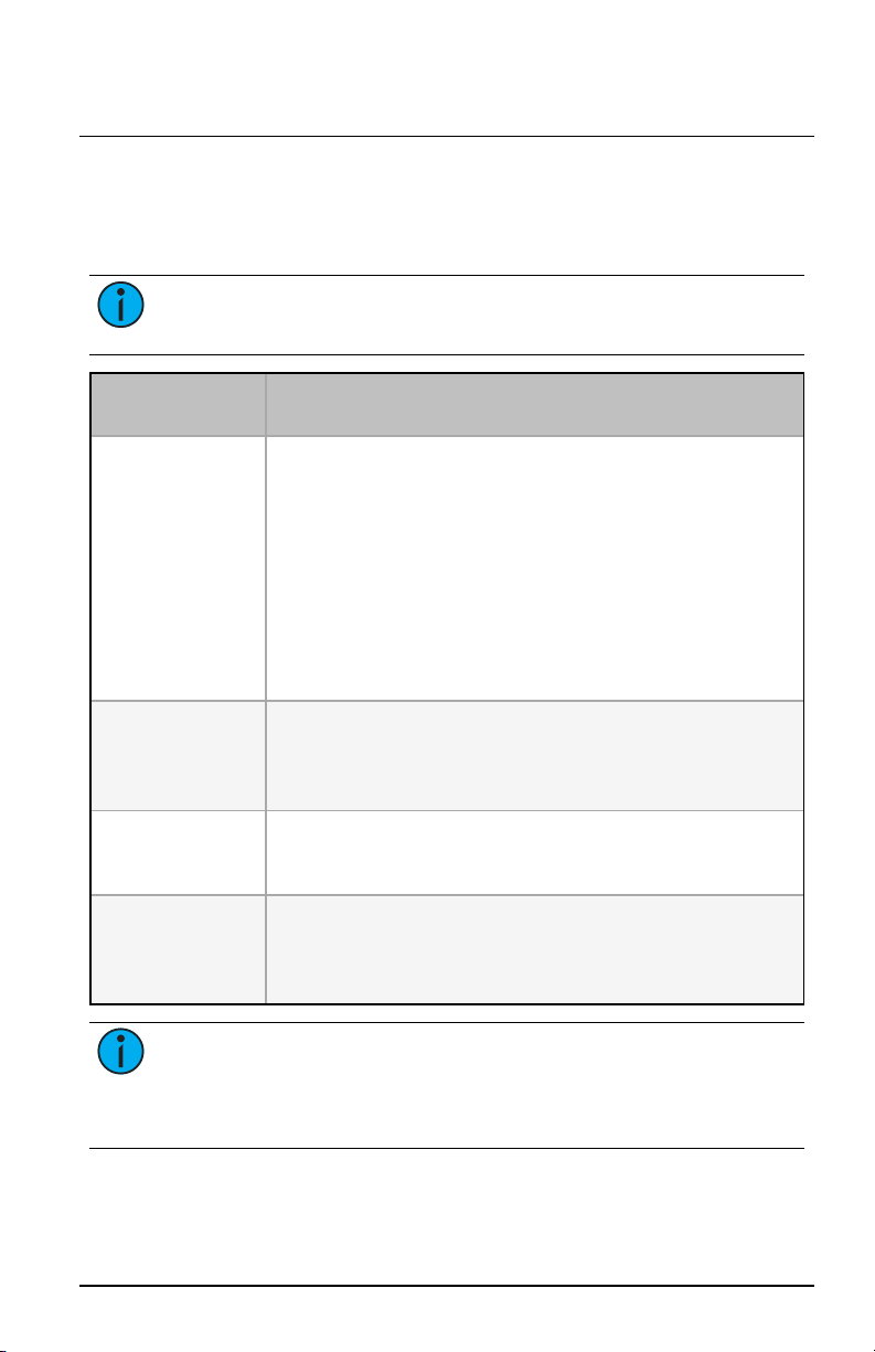
EchoTouch features:
64 Presets shared across the Echo
control system
40 Zones of control (with the first
16 shared across the Echo control
system)
4 internal Sequences (DMX, sACN
and Art-Net only)
®
Corpor at e Headquart er s n Middleton,W isconsin, USA n Tel +608831 4116
Ser v ic e (Am er ic as) n service@etc connect.c om
London, UK n Tel +44 (0)20 88961000n Service: (UK) service@etc europe.com
Rome , IT n Tel +39 (06) 32 111 683 n Servi ce: (UK) ser vice@etc europe.com
Holz ki rc hen, DE n Tel +49 (80 24)47 00-0 n Service: (DE) techserv-hoki@etcconnect.com
Hong Kong n Tel +852 2799 1220 n Ser vic e: (Asia) serv ice@etcasia.com
We b: etcconnect .com n © 2018 Elect ronic Theatre Controls, Inc. n Product i nformation and
specific ations subject to change. n ETC intends this document to be provided in its entir ety.
7186M2109 n Rev B n Released 2018-09
Page 2

ETC Installation Guide
•
•
•
•
•
•
-
-
•
-
EchoTouch Controller
Specifications
Ambient Environment
For indoor use only.
32°F to 104°F (0°C to 40°C) operating temperatures in 0–95% noncondensing humidity.
Compliance
UL and cUL listed
Conforms to EN 62368-1 (Part 1 Safety Requirements)
CE listed
FCC compliant
Electrical and Auxiliary Wiring Specification
EchoTouch is powered by either Auxiliary power or by Power over
Ethernet (PoE 802.3af).
Note: This product is intended for use with a Listed power source (LPS)
marked “Class 2", or LPS rated 24 VDC, minimum 0.59 A, or 48 VDC
(PoE), minimum 0.234 A.
Au xi liary Power - 24 VDC auxiliary power requires two 16 AWG
(1.5 mm2) wires and terminates to the provided removable pluggable
connector. The unit draws 400 mA (typical) during normal operation,
with a maximum of 750 mA draw.
Po wer over Eth ernet - PoE requires Category 5 cable or approved
equal with an RJ45 (Category 5 compliant) connector. EchoTouch
includes an RJ45 receptacle on the back panel for connection of PoE.
As required, separately order an Ethernet Cat5 Termination Kit from
ETC (order part number 4101A2003) which includes building wire
termination supplies, instructions, and an Ethernet patch cable.
Note: PoE and all interconnected information technology equipment
(ITE) are intended for intra-building connection.
Note: When both 24 VDC auxiliary power and PoE are connected to
EchoTouch, auxiliary power will be the preferred input.
EchoTouch requires an ESD Ground wire regardless of installation of
grounded metal conduit.
ESD Ground - requires one 14 AWG (2.5 mm
utilizes the provided ESD ground wire pigtail and 3-position WAGO
221 Series LEVER-NUTS®provided in the installation termination kit.
EchoTouch Controller Pa ge 2 of 12 ET C, Inc.
2
) building wire and
Page 3
ETC Installation Guide
EchoTouch Controller
Control Wiring Specification
EchoTouch can be used with the Echo control system using EchoConnect, and
provides 512 channels of DMX out, and 512 channels of sACN out to a
networked system.
Note: Know the intent of use for this controller in your installation. All
terminations may not be required.
Control Type -
Preferred Wire
EchoCon nect using
Belden 8471 (or
equivalent)
DMX out using
Belden 9729 (or
equivalent)
DMX out using
Category 5 (or higher)
sACN out using
Ethernet network
Notes
EchoConnect isa bidirectional protocol that uses onepair of wires
(data+ and data-). The total combined length of an EchoConnect wire
run (usingrecommended Belden 8471) may not exceed
1,640 feet (500 m).
When using Category5 (or equivalent) cable on the EchoConnect
communication bus, please note that not all topologies are supported.
Careful planning is required to ensure the proper termination and the
wire is pulled appropriately. Refer to the installation guidethat is
provided with the Cat5 Station Termination Kit (7186A1207) for
information to terminate Cat5 wiring.
DMX is installed in a daisy chain topology and includes one pair of wires
(data+ and data-, plus common). The maximum recommendedlength
of the wire run is 1,600’ (487 m). Cablepreparation is required before
termination.
DMX can optionally useCategory 5 cablefollowing the ANSI standard
E1.27-2 (data+and data-, plus common), terminated to T-568B
scheme.
sACN control is over a network using an Ethernet connection to a
gateway or network switch. Asrequired, or der an Ethernet Cat5
Termination Kit (ETCpart number 4101A2003) which includes building
wire termination supplies, instructions, and an Ethernet patch cable.
Note: Wiring should only be installed and terminated by a qualified
technician and should follow standard wiring installation practices. Leave
approximately 8" (20 cm) of wiring in the back box for connection and to
allow slack for future service needs.
EchoTouch Controller Pa ge 3 of 12 ET C, Inc.
Page 4
ETC Installation Guide
•
•
•
ESD ground wire
pigtail (required)
optional spacer
Flush mount
3-gang deep
back box
ESD ground wire
pigtail (required)
Surface mount
back box
EchoTouch Controller
Configuration
This document guides you through the installation of the EchoTouch
controller. For more detailed information about graphic configuration options
available, reference the integrated help system.
Installation
Note: The installation must follow local codes and standard practices.
Note: EchoTouch must be mounted to a vertical surface.
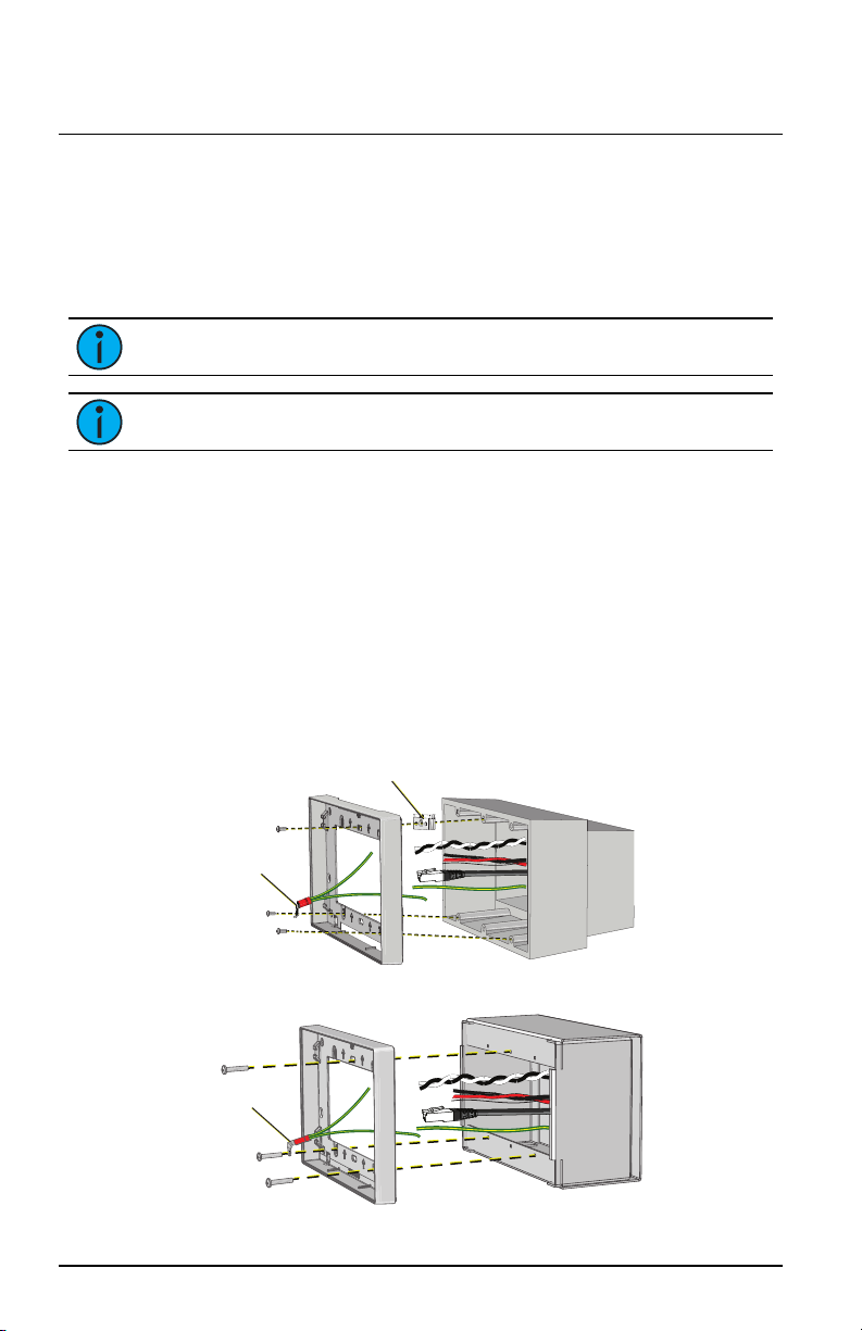
Install the Mounting Collar
EchoTouch installs to a 3-gang deep back box, to the EchoTouch surface
mount back box, or to an EchoTouch Rack-mount kit.
Listed 3-gang deep back box (by others) - in accordance with NEC and
local electrical codes.
EchoTouch Surface-mount back box available from ETC (order part
number 7186A1116-4). If using a surface-mount back box by others, it
must be in accordance with NEC and local electrical codes.
EchoTouch Rack-mount kit available from ETC (order part number
7186A1117). Reference the Rack-mount kit installation instructions
before proceeding with the installation.
EchoTouch Controller Pa ge 4 of 12 ET C, Inc.
Page 5

ETC Installation Guide
•
•
EchoTouch Controller
1.
Install the back box.
Flush-mount back box - when preparing the installation location,
carefully cut the hole in the wall surface material and ensure
there are no gaps around the box.
Surface mount back box - installation hardware is not provided.
The installation location must support up to 5 lbs. (2.3 kg), which
includes the EchoTouch, surface mount back box, and wiring.
Align the surface mount back box to the installation location and
secure in place using four 1/4” (6 mm) mounting bolts or screws
(not provided).
2.
Run all power and control wires to the installation location. Reference
Specifications on page2
page3
for details.
Note: The installation must follow local codes and standard practices.
Use conduit if required.
3.
Install the mounting collar to the back box.
a.
Align the mounting collar to the back box with the arrows
directed up.
b.
Use three mounting screws (provided) to loosely install the
mounting collar to the back box. Install two screws on the
bottom and one screw installed on the center top mounting slot
(as pictured on the previous page) for optimal leveling
adjustment.
c.
Adjust the mounting collar in the slotted mounting holes for a
flush and level installation, then tighten the mounting screws.
and
Control Wiring Specification on
Note: For flush-mount back box installations, receptacle spacers and
two sizes of mounting screws are provided to accommodate a flush
installation. To use spacers, fold the spacer to the thickness needed, trim
and discard the unused sections, then insert the mounting screws through
the spacers when attaching to the back box.
EchoTouch Controller Pa ge 5 of 12 ET C, Inc.
Page 6

ETC Installation Guide
EchoTouch Controller
ESD Ground Termination
Instal l ESD Ground Wire Pigtail
1.
Locate the ESD ground pigtail (2 green/yellow wires with spade
terminal) in the termination kit. This pigtail will be installed on the
bottom left side, between the mounting screw and the mounting
collar on the touchscreen side (as shown above).
a.
Loosen the bottom left screw on the mounting collar and insert
the spade terminal.
b.
Re-tighten the screw for a secure fit.
c.
Gently bend the ESD ground wire spade terminal so the wires
are directed toward the back box.
2.
Locate the 5-position screw terminal connector in the termination kit.
3.
Strip 1/4” (6 mm) of insulation from the end of one ESD ground wire
and insert it into the terminal labeled “Echo ", and secure.
ESD Without Grounded Metal Conduit
1.
Pull an additional ESD ground wire (typically green/yellow) to the
installed back box.
2.
Strip 1/4” (6 mm) of insulation from the end of the incoming wire and
the remaining ESD ground wire from the pigtail.
3.
Locate the 3-position WAGO in the termination kit.
4.
Insert the incoming wire one terminal and the remaining ESD ground
wire pigtail into another terminal, closing the terminal levers onto
each wire. Use the third terminal in the WAGO to continue the ground
wire run as needed.
ESD With Grounded Metal Conduit
1.
Strip 3/8” (1 cm) of insulation from the end of the remaining ESD
ground wire from the pigtail.
2.
Terminate ground wire pigtail to a ground screw inside the grounded
back box.
EchoTouch Controller Pa ge 6 of 12 ET C, Inc.
Page 7

ETC Installation Guide
-+
EchoTouch Controller
EchoConnect Termination
This instruction assumes preparation of Belden 8471 (or equivalent) cable
terminating to the 5-position screw terminal connector provided in the
termination kit.
Note: When using Category5 (or equivalent) cable on the EchoConnect
communication bus, please note that not all topologies are supported.
Careful planning is required to ensure the proper termination and the
wire is pulled appropriately. Refer to the installation guide that is
provided with the Cat5 Station Termination Kit (7186A1207) for
information to terminate Cat5 wiring.
1.
Pull all required wiring (data+, data-) into the back box.
2.
Strip 1/4” (6 mm) of insulation from the ends of each wire.
3.
Terminate EchoConnect wires to the 5-position screw
terminal connector provided. EchoConnect is topology free,
you may install the wires in any combination of bus, star,
loop, or home-run.
a.
Insert the data - (typically black) wire into the terminal
labeled “Echo -” and secure.
b.
Insert the data + (typically white) wire into the
terminal labeled “Echo +” and secure.
EchoTouch Controller Pa ge 7 of 12 ET C, Inc.
Page 8

ETC Installation Guide
-+
EchoTouch Controller
24 VDC Auxiliary Power Termination
EchoTouch requires external power, provided by either a 24 VDC (Class 2)
auxiliary power supply or Power over Ethernet (PoE IEEE 802.3af).
Note: Power over Ethernet (PoE IEEE 802.3af) connects to the RJ45
receptacle on the rear panel.
Note: NEC Class 2 product are to be wired in accordance with NEC
Article 725 and local jurisdiction requirements. All power and control
wiring should be installed and terminated by a qualified installer and
should follow standard wiring installation practices.
Terminate 24 VDC auxiliary power to the 5-position screw terminal connector
provided in the termination kit.
1.
Pull all required wiring (typically a 16 AWG black and red
wire pair) into the back box.
2.
Strip 1/4” (6 mm) of insulation from the end of each wire.
3.
Terminate 24 VDC wires to the 5-position screw terminal
connector provided.
a.
Insert the negative voltage wire (black wire typical)
into the terminal labeled “24V -” and secure.
b.
Insert the positive voltage wire (red wire typical) into the
terminal labeled “24V +” and secure.
EchoTouch Controller Pa ge 8 of 12 ET C, Inc.
Page 9

D1
12
10
11
12
8
5
5
6
7
3
+-
com
ETC Installation Guide
EchoTouch Controller
DMX Cable Preparation and Termination
Note: Not for use with Cat5, Cat5e, or Cat6 cable. When running DMX
with these cable types, use the provided 3-position IDC connector and
reference DMX Cat5 Cable Preparation and Termination on the next
page.
This instruction assumes preparation of Belden 9729 (or equivalent) cable
for termination to the 3-position screw terminal connector provided.
1.
Cut cable so that an 8” (20 cm) tail extends from the edge of the
installed back box.
2.
Strip 7” (18 cm) off the outer jacket.
3.
Label the cable with the data type and run
designation. (DMX1, DMX2, etc.)
4.
Strip the foil shielding from each wire set
to within 1/4” (6 mm) of the outer jacket.
5.
Untwist the shield wire from each pair and
apply a piece of 1/16” (1.6 mm) clear heat
shrink to each shield wire.
6.
Twist each shield wire back onto its data
pair, and then apply a 1.5” (4 cm) piece of
3/16” (0.5 cm) heat shrink all the way down
each
3-wire set. Make sure to capture the foil
shielding at the base.
7.
Apply the 2” (5 cm) piece of the 3/8” (1 cm)
heat shrink, centered on the end of the
cable jacket and the bases of all the wires
EchoTouch Controller Pa ge 9 of 12 ET C, Inc.
in the cable.
8.
Cap the ends of the unused pair of wires
with a 1” (2.5 cm) piece of 3/16” (0.5 cm)
heat shrink centered over the end of the
wires.
9.
Strip 1/4” (6 mm) of insulation from all of the wires to be used.
10.
Maintain the wire pair twist as close to the screw terminal connector as
possible and terminate the wires.
a. Insert the common (shield) wire into the terminal labeled
“DMX " and secure.
b.
Insert the data - wire (typically black) into the terminal labeled
“DMX-” and secure.
c.
Insert the data + wire (typically red or white) into the terminal
labeled “DMX+” and secure.
Page 10

ETC Installation Guide
C
OM W/
BRN
Data -
O
R
G
Dat
a
+
(
W/O
RG)
•
•
•
Mounting
tabs (x4)
Ethernet portPoE, sACN,
Art-Net
24 VDC
ESD ground
EchoConnect
DMX out
Installation
orientation
USB port
Reset button
Status
EchoTouch Controller
11.
Bend back the unused set of wires and secure them to the cable with a
wire tie.
12.
Secure the terminated wire sets together with a wire tie 2” (5 cm) from
the connector.
DMX Cat5 Cable Preparation and Termination
This instruction assumes use of Cat5 (or equivalent) cable for termination
to the 3-position Cat5 insulation displacement connector provided in the
termination kit.
1.
Follow normal Cat5 wire installation procedures to remove 2”
(50 mm) from the end of the cable jacket.
2.
Separate the White/Brown, Orange, and White/Orange conductors
from the cable. These conductors are required for DMX out.
3.
Cut the remaining unused conductors from the cable flush to
the cable jacket.
4.
Label the cable with the data type and run designation (for
example D1 for DMX run 1).
5.
Twist the White/Orange and Orange conductors as close to
the 3-position IDC as possible and insert the conductors
through the labeled terminals as follows:
Common (White/Brown) to terminal 1
Data - (Orange) to terminal 2
Data + (White/Orange) to terminal 3
6.
Fully depress each terminal, closing it onto the wire.
7.
Use side-cutters to trim the excess wire from the connector.
Install Touchscreen
1.
Align but do not install the touchscreen to the mounting collar. Ensure
the touchscreen is oriented with the label text and molded rear panel
arrow directed up.
2.
Install the prepared 5-position screw terminal connector (24 VDC, ESD
Ground, and EchoConnect control wires) and the utilized 3-position
EchoTouch Controller Pa ge 10 of 12 ET C, Inc.
connector (DMX) to the designated receptacle(s) on the rear panel of
Page 11

ETC Installation Guide
•
•
•
EchoTouch Controller
the unit. This instruction assumes you have prepared the cables and
terminated them according to the provided instructions for your
installation type.
3.
If using Power over Ethernet to power the EchoTouch, install the
Ethernet cable to the receptacle on the rear panel of the unit.
4.
Press the touchscreen into the mounting collar until the screen is flush.
You will hear an audible click when the mounting tabs have fully
seated into position.
5.
Apply power to the unit. After boot up, press the {?} button located at
the top left of the display to access the EchoTouch online help system
which provides information to setup and configure your touchscreen.
Release EchoTouch from the Mounting Collar
Access to the back of the touchscreen is required for the following operations:
to access the provided USB port for firmware update (see
Firmware on the next page
to download a configuration file (see online help system)
to troubleshoot control wiring
This procedure requires a flat blade jewelers screwdriver (not provided).
1.
Gently press the tip of a jewelers screwdriver up into the provided slot
on either side of the mounting collar to release the touchscreen
mounting clips. You will hear and feel an audible click when the clip is
released, and the bottom of the EchoTouch touchscreen will be free of
the collar.
2.
Repeat for the opposite side of the touchscreen.
)
Update
3.
Carefully pull on each vertical edge of the touchscreen to remove it
from the collar.
Note: Be careful not to pull on any of the installed cables.
EchoTouch Controller Pa ge 11 of 12 ET C, Inc.
Page 12

ETC Installation Guide
EchoTouch Controller
Update Firmware
1.
Copy the firmware update file on the root directory of a USB drive that
has been formatted to FAT32. The file will be named similarly to ETC_
CS_Console_#.#.#.#.fw, where # will be replaced with the version
numbers.
Note: Please make sure the software file is not inside any other folder
or subdirectory, as this will hide it from the EchoTouch update function.
2.
The EchoTouch should remain powered, but carefully
removed from the mounting collar to gain access to
the rear panel. Reference
the Mounting Collar on the previous page
instructions.
3.
Insert the USB drive into the EchoTouch USB
receptacle located on the underside of the rear panel.
4.
Access the front of the touchscreen and navigate to
Setup >Files >Advanced >Update Firmware.
A confirmation message will display. Select “Yes” to
continue with the update
Release EchoTouch from
for
CAUTION : The update process may take a few minutes. Do not
shutdown or remove power from the touchscreen until the update process
has finished. When prompted, restart the touchscreen by pressing the
Reset button located near the USB port.
5.
When the touchscreen has booted, navigate to the General tab in
Settings to verify the updated software version number is displayed.
6.
Disconnect the USB drive from the rear panel of the unit.
7.
Check that all connectors and cables are fully seated then reinstall the
touchscreen into the mounting collar.
EchoTouch Controller Pa ge 12 of 12 ET C, Inc.
 Loading...