

Page 1
ETC Installation Guide
24VDC
Power
Supply
EchoConnect
Station
Power Supply
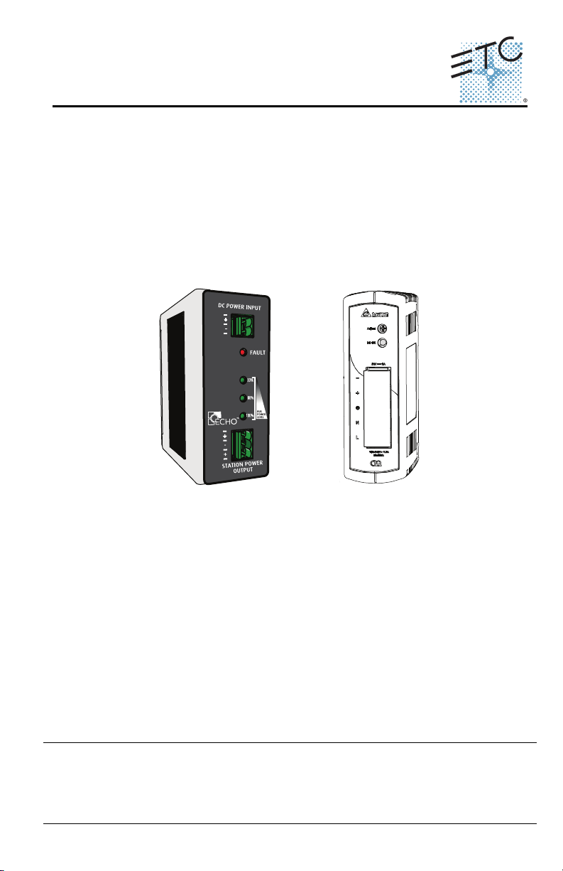
EchoConnect® DIN Rail Power Supply
Overview
The EchoConnect DIN Rail Station Power Supply provides EchoConnect bus
power for up to 16 sensors/stations and 16 power controllers as well as Aux
24VDC for Echo products that require it. This product consists of two
components that must be used together: the EchoConnect Power Supply and
the 24VDC Aux supply that feeds DC power to it.
This document details the installation of both components in a DIN rail
enclosure. DIN rail enclosure not included.
Included in the shipment:
• EchoConnect DIN Rail Station Power Supply
• 24VDC DIN rail mount power supply
• Red and black power harness
• Green station header
Corporate Headquarters Middleton, Wisconsin, USA Tel +608 831 4116 Service: (Americas) service@etcconnect.com
London, UK Tel +44 (0)20 8896 1000 Service: (UK) service@etceurope.com
Rome, IT Tel +39 (06) 32 111 683 Service: (UK) service@etceurope.com
Holzkirchen, DE Tel +49 (80 24) 47 00-0
Hong Kong Tel +852 2799 1220 Service: (Asia) service@etcasia.com
Web: www.etcconnect.com
Product information and specifications subject to change
7186M2107 Rev A Released 2016-05
DIN Rail Station Power Supply Page 1 of 7 Electronic Theatre Controls, Inc.
Copyright © 2016 ETC. All Rights Reserved.
Service: (DE) techserv-hoki@etcconnect.com
. ETC intends this document to be provided in its entirety.
Page 2

ETC Installation Guide
DIN Rail Station Power Supply
Specifications
Ambient Environment
For indoor use only. Supports plenum rating:
• 32°F to 122°F (0°C to 50°C) operating temperatures in 5-95% noncondensing humidity
Electrical Specification
• 24VDC Power Supply: Mains input 100-240VAC, 50/60 Hz, provides
30W at 24VDC in addition to the power required for the Station Power
Supply.
• DIN Rail Station Power Supply: 24VDC input, powers up to 16 Echo
sensors/stations and 16 power controllers over EchoConnect.
Compliance
• UL and cUL listed
• FCC and CE compliant
EchoConnect
EchoConnect is a two-wire, topology-free protocol that provides power for up
to sixteen Echo sensors and stations or sixteen power controllers.
EchoConnect is a bidirectional protocol that uses one pair of wires (data+ and
data-) for both data and power. ETC recommends using Belden 8471 (or
approved equal) Class II wire.
The total combined length of an EchoConnect wire run (using Belden 8471, or
equal) may not exceed 1,640 feet (500m).
Note:
DIN Rail Station Power Supply Page 2 of 7 Electronic Theatre Controls, Inc.
All control wiring should be installed and terminated by a
qualified installer and should follow standard wiring
installation practices.
Page 3
ETC Installation Guide
Step 3
Step 4
DIN Rail Station Power Supply
Prepare for Installation
The DIN Rail Station Power Supply and 24VDC power supply are designed for
mounting directly to DIN rail (provided by others) anywhere on the
EchoConnect station bus.
Installation
Follow all local codes and standard electrical practices. Ensure the installation
area is clean and free of obstructions and that all wiring is installed correctly.
WARNING:
Step 1: Locate the circuit breaker panel and turn off the power to the
Step 2: Locate both the 24VDC power supply and the Station Power
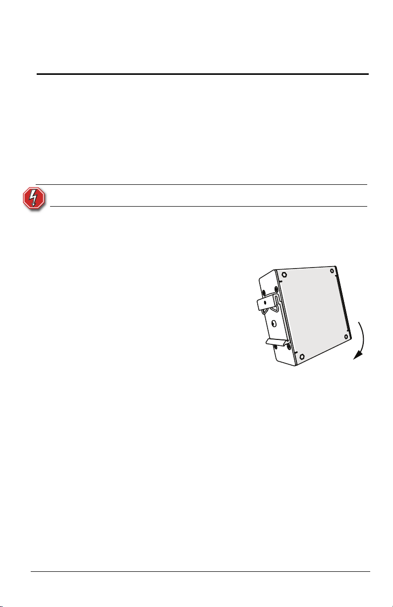
Step 3: Hook the top DIN rail
Step 4: Rock the Power Supply
Step 5: Repeat for the second
For indoor use only!
circuit.
Supply.
clip over the top of the
DIN rail.
downward until the
bottom clip snaps into
place, securing the
unit to the DIN rial.
power supply.
DIN Rail Station Power Supply Page 3 of 7 Electronic Theatre Controls, Inc.
Page 4

ETC Installation Guide
screw
terminals
DIN Rail Station Power Supply
Connect EchoConnect
Remove the provided green connector and terminate the EchoConnect wires
to it. Terminations include a black wire (data -), a white wire (data +), and a
green/yellow wire (ESD). EchoConnect is topology free, you may install the
wires in any combination of bus, star, loop, or home-run.
Note:
When using Category5 (or equivalent) cable on the
EchoConnect communication bus, please note the following:
- Not all topologies are supported using Cat5. Ensure the
proper termination kits are available and the wire is pulled
appropriately.
- Cat5 wiring may be terminated using the EchoConnect Cat5
Station Termination Kit (7186A1207.) Refer to the installation
guide provided with the Cat5 Station Termination Kit for Cat5
wiring termination information.
Step 1: Pull all required wiring (data +, data -, and ground wire) to the
power supply. Strip each wire 1/4”
Step 2: Remove the green
header from the
Station Power
Output.
Step 3: Use a flat blade
screw driver to
loosen the three
screw terminals.
Step 4: Insert the ground
wire into a terminal
and tighten the
screw.
Step 5: Insert the black (data -) wire into a terminal and tighten the
screw.
Step 6: Insert the white (data +) wire into a terminal and tighten the
screw.
Step 7: Reattach the green header to the Station Power Supply.
DIN Rail Station Power Supply Page 4 of 7 Electronic Theatre Controls, Inc.
Page 5

ETC Installation Guide
Existing harness to
Station Power
Supply
(red & black)
Green (ground)
White (N)
Black (L)
Clear plastic
cover
Provided green
header to
EchoConnect
Mains power:
DIN Rail Station Power Supply
Connect mains power input
The mains power input connects to the face of the included 24VDC Power
Supply.
Step 1: Pull all required wiring (ground, line hot, and neutral) to the
installed power supply and crimp the end of each wire with a
Y-connector. (not provided)
Step 2: Remove the plastic cover protecting the screw terminations
with a gentile pull.
Step 3: Remove the L (line hot), N (neutral), and (ground) termination
screws.
Step 4: Place the crimped connector of the green (16 AWG, ground)
wire over the ground termination hole and reattach the screw,
tightening it completely.
Step 5: Place the crimped connector of the white (16 AWG, neutral)
wire over the N termination hole and reattach the screw,
tightening it completely.
Step 6: Place the crimped connector of the black (16 AWG, hot) over
the L termination hole and reattach the screw, tightening it
completely.
DIN Rail Station Power Supply Page 5 of 7 Electronic Theatre Controls, Inc.
Page 6

ETC Installation Guide
DIN Rail Station Power Supply
Step 7: Locate the provided red and black wire harness.
Step 8: Loosen the (+) and (-) screws on the face of the 24V power
supply.
Step 9: Place the Y-connector of the black wire under the (-) screw.
Tighten the screw to hold the wire firmly in place.
Step 10: Place the Y-connector of the red wire under the (+) screw.
Tighten the screw to hold the wire firmly in place.
Step 11: Reattach the clear plastic cover over the screw terminations.
Step 12: Plug the black connector into the DC POWER INPUT on the
face of the Station Power Supply.
DIN Rail Station Power Supply Page 6 of 7 Electronic Theatre Controls, Inc.
Page 7

ETC Installation Guide
DIN Rail Station Power Supply
Power Up and Test
Restore power to the circuit. The BUS POWER LEVEL LED will illuminate green.
If a fault is discovered in the control wiring, the BUS POWER LED will turn off
and the FAULT indicator will illuminate.
Note:
This condition typically means that the station wiring has a fault;
however it could mean a connected device is having an issue. A
qualified technician should inspect the system wire and terminations
first, then proceed to disconnecting devices to pinpoint the fault and
correct it.
The power supply will update the fault indicator automatically when
the fault condition is cleared.
DIN Rail Station Power Supply Page 7 of 7 Electronic Theatre Controls, Inc.
Page 8

 Loading...