

Page 1
ETC Setup Guide
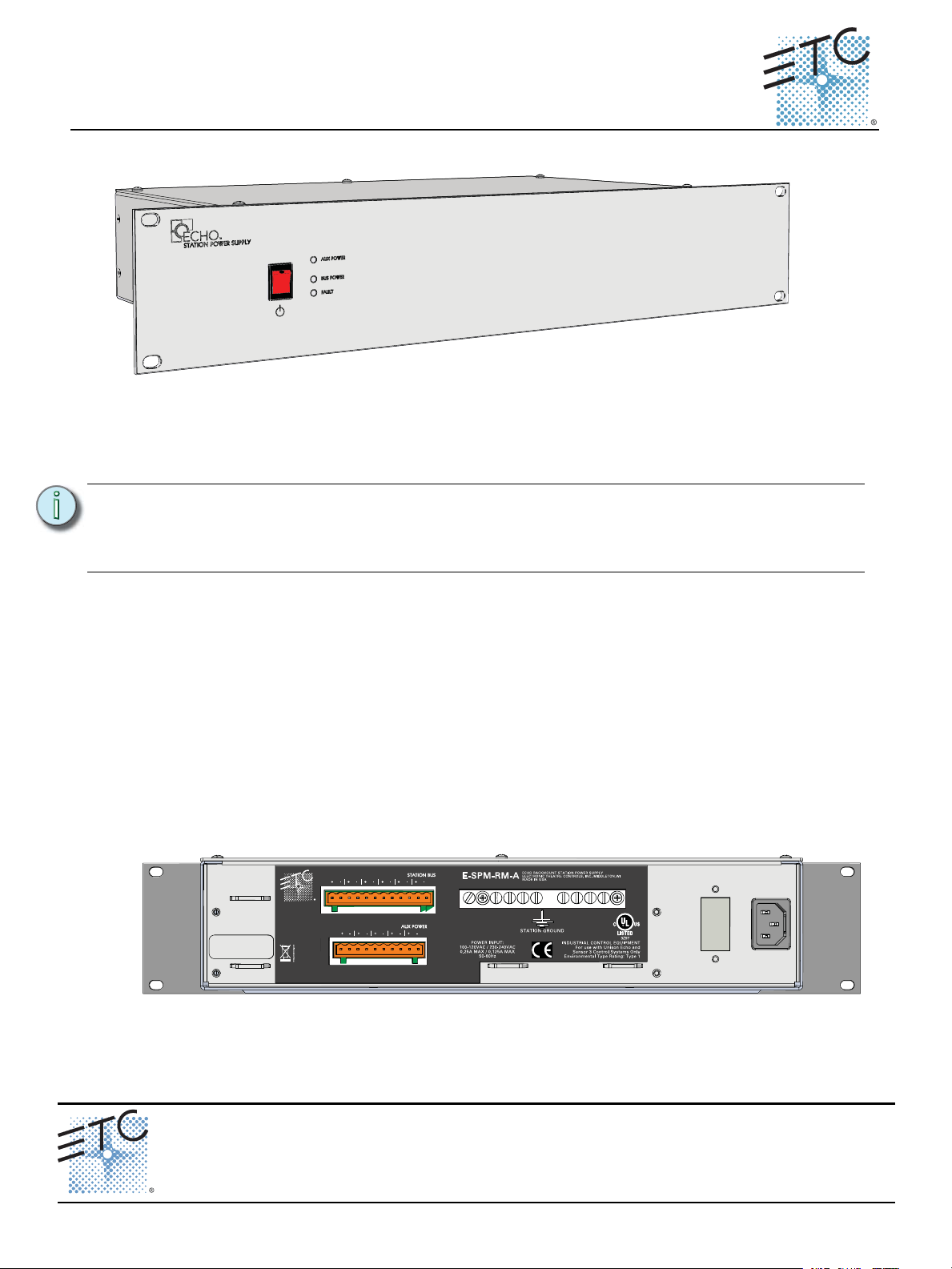
Unison Echo™ Rack Mount Station Power Supply w/ Aux Power
Overview
The Echo Rack Mount Station Power Supply with Auxiliary Power (E-SPM-RM-A) is designed for use with
the Echo control system to supply bus power for up to 16 Echo architectural control stations on the
topology-free EchoConnect control network and provides 24 Vdc auxiliary power (maximum 36 watts) for
Echo devices. The E-SPM-RM-A also supports connection of up to 16 compatible power panels or
distributed power controllers over EchoConnect.
Note:
If you are using Cat5 (or Cat5e) wiring, an external Echo Cat5 Termination Tray is
required. Contact ETC for ordering details. Control wiring instructions between the
termination tray and this Rack Mount Station Power Supply with Auxiliary will be
provided with the Unison EchoConnect Cat5 Termination Tray installation instructions.
For use with ETC Dimming and Relay Products.
Installation
Install Unit in Equipment Rack
The E-SPM-RM-A utilizes 2U of rack space.
Step 1: Locate the included rack mounting hardware kit including the mounting screws and
washers.
Step 2: Use the hardware provided to mount the unit to the mounting rails in your equipment rack.
Power and Control Wiring
The rack mount enclosure is provided with wiring connections on the rear of the unit.
• AC Power
• EchoConnect (Station Bus) and ESD Ground
• 24 Vdc Auxiliary power
Corporate Headquarters Middleton, WI, USA Tel +608 831 4116 Service: (Americas) service@etcconnect.com
London, UK
Rome, IT
Holzkirchen, DE
Hong Kong
Web: www.etcconnect.com
7186M2202
Rack Mount Station Power Supply with Auxiliary Page 1 of 3 Electronic Theatre Controls, Inc.
Tel +44 (0)20 8896 1000 Service: (UK) service@etceurope.com
Tel +39 (06) 32 111 683 Service: (UK) service@etceurope.com
Tel +49 (80 24) 47 00-0 Service: (DE) techserv-hoki@etcconnect.com
Tel +852 2799 1220 Service: (Asia) service@etcasia.com
Rev A Released 2015-06 ETC intends this document to be provided in its entirety.
© 2015 ETC. All Rights Reserved. Product information and specifications subject to change.
Page 2

ETC Setup Guide
Rack Mount Station Power Supply with Auxiliary
Connect Power
Three IEC power cables are provided with this unit from the factory including US, UK, and Shuko. Supply
the Echo Station Power Supply with a single phase of 100-120VAC (.25A max) or 230-240 VAC
(.125A max), 50-60Hz.
Step 1: Connect the regional specific IEC power cable to the receptacle on the rear of the unit.
Connect EchoConnect (Station Bus) Wiring and ESD Ground
Termination is available for up to six runs of EchoConnect station bus wiring to the removable pluggable
connector labeled “Station Bus” on the rear panel of the unit. EchoConnect is a two-wire topology-free
system that allows the E-SPM-RM-A to provide power for up to 16 Echo sensors and stations and allows for
up to 16 power controllers. EchoConnect is a bidirectional protocol that uses one pair of wires (data+ and
data-) for both data and power. ETC recommends using Belden 8471 (or approved equal) Class II wire.
Note:
ETC requires that all stations be grounded. Pull an additional 14 AWG (2.5mm
provided ESD Ground terminal bar when control wires are not installed in grounded metal conduit.
Step 1: Remove the 16 pin screw terminal connector labeled “Station Bus” from the rear panel.
Step 2: Connect the Belden 8471 wires to the two pin screw terminal connector. This connection is
Step 3: Replace the connector to the rear panel.
Step 4: When required, terminate the 14 AWG (2.5mm
The total combined length of an EchoConnect wire run (using Belden 8471, or equal) may
not exceed 1,640 feet (500m).
2
) wire for grounding to the
polarity dependent. Refer to the connector label for notation of “data+ and data-”.
• Connect the white wire to the data + terminal.
• Connect the black wire to the data - terminal.
2
) Echo station ESD ground wire to the
provided ground terminal bar on the rear of the unit.
Connect 24 Vdc Auxiliary Power Wiring
Termination is provided for up to 5 runs of auxiliary power to the removable pluggable connector labeled
“Aux Power” on the rear panel of the unit. Auxiliary power provides 24 Vdc power that is required to
power compatible Echo devices.
Step 1: Remove the 10 pin screw terminal connector labeled “Aux Power” from the rear panel.
Step 2: Connect the auxiliary power wires, typically 16 AWG (1.5mm
terminals. This connection is polarity dependent. Refer to the connector label for notation of
“+ and -”.
• Connect the red wire to the + terminal.
• Connect the black wire to the - terminal.
Step 3: Replace the connector to the rear panel.
2
) red/black wire pair into the
Rack Mount Station Power Supply with Auxiliary Page 2 of 3 Electronic Theatre Controls, Inc.
Page 3

ETC Setup Guide
Rack Mount Station Power Supply with Auxiliary
Final Installation
Step 1: Plug the IEC power cable into the power source.
Step 2: Secure all cables to the enclosure using cable ties (not provided). Four mounts are provided
on the rear panel of the unit.
Step 3: Supply power to the unit.
Step 4: Press the power switch, located on the front of the unit, to the On position.
Step 5: Check status indicators for faults.
Status Indicators
When power is applied to the unit, the “Bus Power” and “Aux Power” LEDs located on the front panel
illuminates.
Bus Power LED
If a fault is discovered in the control wiring, the Bus Power LED turns off and the Fault indicator will
illuminate. This condition typically means that the station wiring has a fault; however it could mean a
connected device is having an issue. A qualified technician should inspect the system wire and terminations
first, then proceed to disconnecting devices to pinpoint the fault and correct it.
The power supply will update the fault indicators automatically when the fault condition is cleared.
Aux Power LED
The “Aux Power” LED will be illuminated as long as the power supply is powered and is supplying 24 Vdc
auxiliary output power.
Rack Mount Station Power Supply with Auxiliary Page 3 of 3 Electronic Theatre Controls, Inc.
 Loading...