

Page 1
ETC Installation Guide
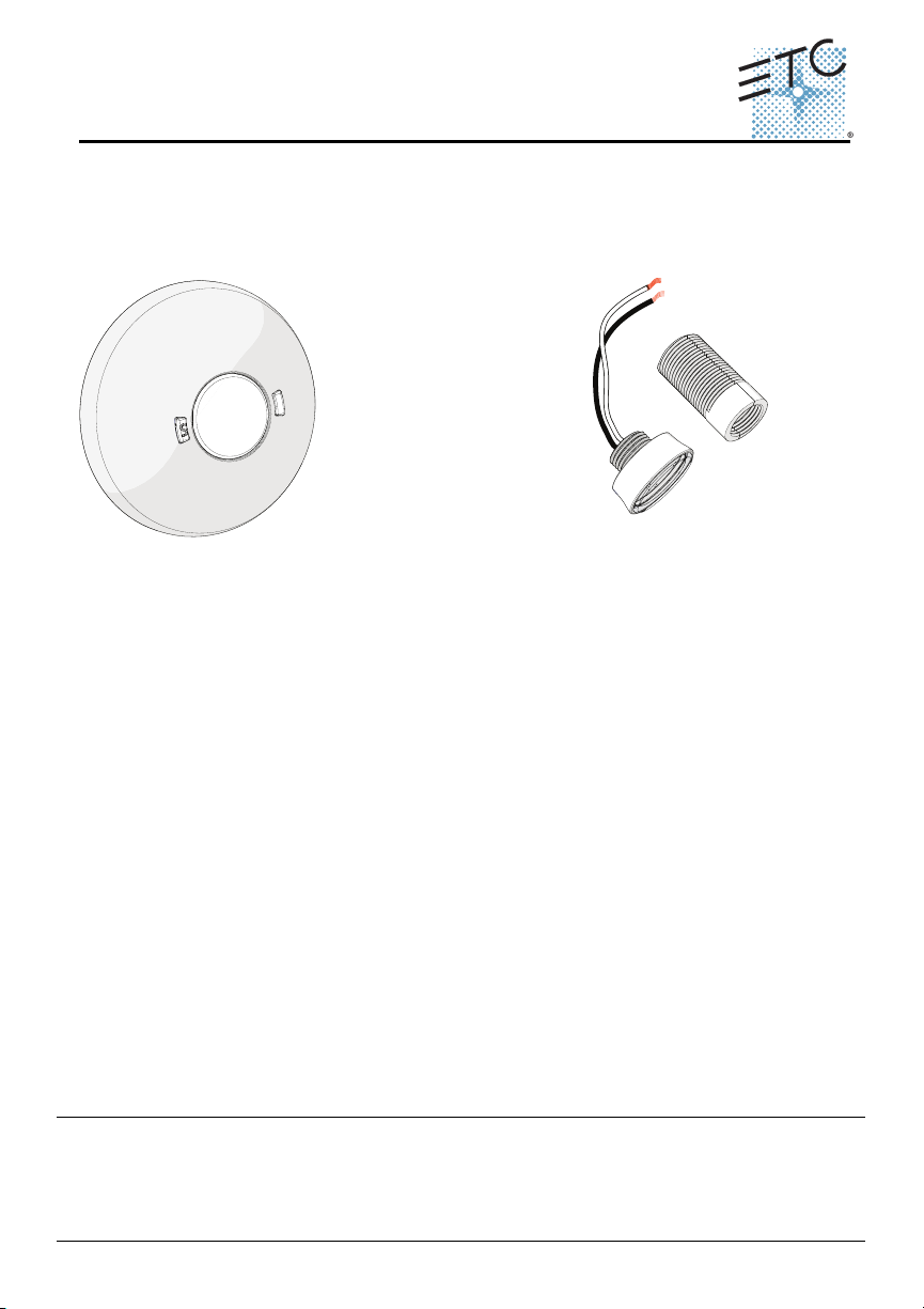
light sensor with
controller
light sensor
thread
extender
Unison Paradigm® Light Sensor
Overview
The Unison Paradigm® Light Sensor provides light level measurement to the
connected Paradigm control system. The control system receives the measurements
to maintain a programmed lighting output in both dimmed and switched lighting
systems.
The Paradigm Light Sensors are available in three models:
• P-LS - Light Sensor with Controller
• P-LSC - Light Sensor Controller Only
• P-LSH - Light Sensor Only
Each controller supports an individual pair of Light Sensors and is available in neutral
white or black finish.
A light sensor may be installed within the controller or installed remotely, using up to
1,000 feet (304m) of 16 AWG wire per controller. When using a pair of light sensors,
both sensors transmit their light readings to a single controller which provides an
averaged reading to the connected Paradigm control system.
Wire Specification
Controller
The Paradigm Light Sensor utilizes LinkConnect to power the sensor and to provide
data to and from the connected Paradigm control system.
LinkConnect is topology-free and polarity independent. You can install your data runs
in any desired combination of bus, star, loop, and home-run. ETC recommends using
Belden 8471 (or equivalent) wire. The total combined length of a LinkConnect wire
run may not exceed 1,640 feet (500m), with a maximum distance of 1,312 feet (400m)
between any two devices.
Corporate Headquarters
London, UK
Unit 26-28, Victoria Industrial Estate, Victoria Road, London W3 6UU, UK Tel +44 (0)20 8896 1000 Fax +44 (0)20 8896 2000
Rome, IT
Via Pieve Torina, 48, 00156 Rome, Italy Tel +39 (06) 32 111 683 Fax +44 (0)20 8752 8486
Holzkirchen, DE
Hong Kong Rm 1801, 18/F, Tower 1 Phase 1, Enterprise Square, 9 Sheung Yuet Road, Kowloon Bay, Kowloon, Hong Kong Tel +852 2799 1220
Service:
(Americas) service@etcconnect.com
Web:
www.etcconnect.com
7184M2170
Rev A Released 2012-12 ETC intends this document to be provided in its entirety.
Unison Paradigm Light Sensor Installation Guide Page 1 of 8 Electronic Theatre Controls, Inc.
3031 Pleasant View Road, P.O. Box 620979, Middleton, Wisconsin 53562-0979 USA Tel +608 831 4116 Fax +608 836 1736
Ohmstrasse 3, 83607 Holzkirchen, Germany Tel +49 (80 24) 47 00-0 Fax +49 (80 24) 47 00-3 00
Copyright © 2012 ETC. All Rights Reser ved. Product information and specifications subject to change.
(UK) service@etceurope.com (DE) techserv-hoki@etcconnect.com
(Asia) service@etcasia.com
Page 2
ETC Installation Guide
Light Sensor
All control wiring should be installed and terminated by a qualified installer, should
follow standard wiring installation practices, and meet local codes. Leave
approximately 10 inches (254mm) of wiring in the junction box or tied back in the
ceiling to allow for wiring connections and future service needs.
Note:
ETC requires that all stations be grounded by using a 14 AWG (2.5mm2)
ESD drain wire.
Remoting the Light Sensor
The Paradigm Light Sensor Controller provides termination for up to two light
sensors. Each light sensor must be separately wired to the controller using no more
than 1000 feet (304m) of 16 AWG wire total per controller. These wire runs must
remain separate from LinkConnect wiring. ETC recommends using Belden 8471 (or
equivalent) wire.
Installation Environment
The Paradigm Light Sensor Controller is intended for installation to a finished ceiling
surface, soft ceiling tile, attached to a round fixture junction box or single-gang RACO
switch box. The controller operates in ambient temperatures of 0°C to 40°C, noncondensing humidity.
The Paradigm Light Sensor can be mounted directly in the controller, installed to a
1/2” conduit knockout or installed into a soft ceiling tile using the provided light
sensor thread extender. The light sensor can be installed outdoors when mounted to
a weatherproof enclosure. The sensor in this weatherproof installation scenario
operates in ambient temperatures of -25°C to 70°C.
Parts and Supplies
The following parts and supplies are included with the specific Paradigm Light Sensor
assembly ordered:
Light Sensor
Parts and Supplies
soft ceiling tile adaptor XX
LinkConnect and ground wire pigtails X X
light sensor thread extender XX
3 position WAGO connectors X X
2 position WAGO connectors X
1 each nuts and washers 3/4” and 1” X X
2 each screws 6-32 x 3/4” and 1 3/4” XX
blank sensor head X X
complete
unit (P-LS)
Light Sensor
only
(P-LSH)
Light Sensor
Controller
only (P-LSC)
Unison Paradigm Light Sensor Installation Guide Page 2 of 8 Electronic Theatre Controls, Inc.
Page 3
ETC Installation Guide
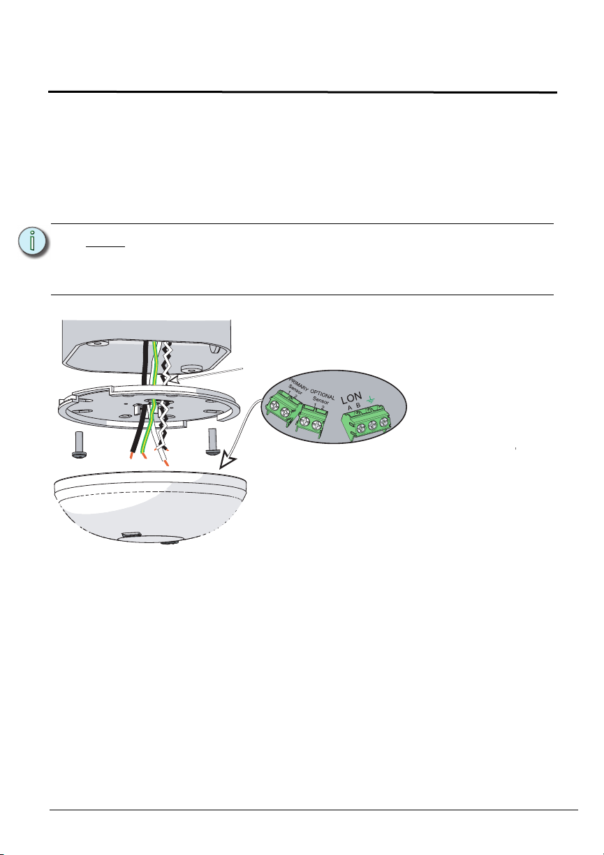
terminate
wires here
optional
sensor wires
Termination is available at the controller for LON
(LinkConnect) from the data source (Paradigm), and up
to two light sensors. Flexibility is provided with regards
to how the light sensor(s) is installed. You can install a
light sensor at the controller or up to two light sensors
can be installed remotely.
Light Sensor
Installation
The Paradigm Light Sensor is provided with a twist-lock mounting plate that can be
mounted to a finished ceiling, junction box, or soft ceiling tile. Determine the
installation method and follow the specific instructions detailed.
• "Junction Box Installation" on page 3
• "Soft Ceiling Tile Installation" on page 5
• "Installing the Light Sensors Remotely (optional)" on page 6
Note:
The LinkConnect pigtail and WAGO connectors provided are only
required when the sensor and controller are installed in series with other
sensors. If you are not continuing the data run, direct termination is
recommended on the sensor control board.
Junction Box Installation
Step 1:Pull Belden 8471 (or equivalent) and 14 AWG (2.5mm2) ground wire to the
junction box.
Unison Paradigm Light Sensor Installation Guide Page 3 of 8 Electronic Theatre Controls, Inc.
Page 4

ETC Installation Guide
installed control wire
installed control wire to next stati
on
sensor pigtail
a: Strip 3/16” (5mm) of insulation from each installed LON
wire.
b: Open the three terminal levers on a WAGO connector
and insert the installed (typically black) Belden 8471
LinkConnect wire, the black lead from the sensor pigtail,
and the continuing Belden 8471 (typically black) wire into
the terminals.
c: Close the levers onto the wires.
d: Repeat the above for the installed (typically white)
Belden 8471 LinkConnect wire and the remaining pigtail
from the sensor, as well as the ESD ground wires using
a new WAGO connector and the ground pigtail for each
termination type.
Light Sensor
Step 2: If you are installing the controller in series with other sensors, sensor
controllers, or stations (continuing the data run), use the provided LinkConnect
pigtail, ESD ground pigtail and WAGO connectors to make the terminations. If
you are not continuing the data run, proceed to step 4.
Note:
Primary Sensor and Optional Sensor wires should terminate directly to
the terminals located on the controller. See “Installing the Light Sensors
Remotely (optional)” on page 6.
Step 3: If you are installing the primary and/or optional second light sensor
remotely from the controller, reference "Installing the Light Sensors Remotely
(optional)" on page 6, then return to these instructions. If you are not remoting
a light sensor, proceed to step 4.
Step 4:Orient the smooth side of the mounting plate to the junction box and pull each
run of Belden 8471 (LON and remote sensor wires) and the 14 AWG (2.5mm
ESD drain wire from the junction box through the provided holes near the
center of the mounting plate.
Step 5:Secure the mounting plate to the junction box using the screws provided (both
short and long screws are included for convenience).
Step 6: Strip each wire 5/16” (8mm) and terminate the white, black, and green (ground)
wires to the LON terminal block located on the sensor control board. Torque
each termination to 3.1-3.5 in-lb.
a: Terminate the white incoming wire to terminal A.
b: Terminate the black incoming wire to terminal B.
c: Terminate the green wire to the labeled ground terminal.
Step 7: If the primary or an optional second light sensor is installed remotely
from the controller, reference "Installing the Light Sensors Remotely (optional)"
on page 6 for termination instructions, then return to these instructions.
Otherwise, proceed to step 8.
Step 8:Attach the sensor to the mounting plate by aligning the tabs on the sensor with
Unison Paradigm Light Sensor Installation Guide Page 4 of 8 Electronic Theatre Controls, Inc.
the slots on the mounting plate, then twist clockwise until the two are locked
into place.
2
)
Page 5

ETC Installation Guide
poke the adapter through the ceiling tile, then bend
it over for a secure fit.
LinkConnect pigtail and
WAGO connectors
(optional use)
terminate
wires here
optional
sensor wires
a: Strip 3/16” (5mm) of insulation from each installed wire.
b: Open the three terminal levers on a WAGO connector and
insert the installed (typically black) Belden 8471
LinkConnect wire, the black lead from the sensor pigtail,
and the continuing Belden 8471 (typically black) wire into
the terminals.
c: Close the levers onto the wires.
d: Repeat the above for the installed (typically white) Belden
8471 LinkConnect wire and the remaining pigtail from the
sensor, as well as the ESD ground wires using a new
WAGO connector for each termination type.
Light Sensor
Soft Ceiling Tile Installation
Step 1:Pull the Belden 8471 (or equivalent) and 14 AWG (2.5mm2) ground wire to the
installation location.
Step 2:Orient the smooth side of the mounting plate to the ceiling tile and insert the
soft ceiling tile adaptor through the two small holes near the center of the
mounting plate.
Step 3:Poke the tines through the ceiling tile, then bend each tine over in opposite
directions for a secure fit.
Step 4: If you are installing the sensor in series with other sensors or stations
(continuing the data run), use the provided LinkConnect pigtail, ESD ground
pigtail and WAGO connectors to make the terminations. If you are not
continuing the data run, proceed to step 5.
Step 5: If you are installing the primary and/or optional second light sensor
installed control wire to next stati
on
remotely from the controller, reference "Installing the Light Sensors Remotely
(optional)" on page 6, then return to these instructions. If you are not remoting
a light sensor, proceed to step 6.
installed control wire
sensor pigtail
Unison Paradigm Light Sensor Installation Guide Page 5 of 8 Electronic Theatre Controls, Inc.
Page 6

ETC Installation Guide
installed with
thread extender
installed without extender
Two light sensors may be connected to the
controller and installed remotely. Each light sensor
must be separately wired to the controller using no
more than 1000 feet (304m) of 16 AWG wire total
per controller. These wire runs must remain
separate from LinkConnect wiring. ETC
recommends using Belden 8471 (or equivalent)
wire.
Step 1:Prepare a hole in the sensor
installation location (3/4” hole without
adapter or 1” with adapter).
Light Sensor
Step 6:Create a hole for wire pass-through in the ceiling tile by poking through the
center hole or oblong hole of the mounting plate, then pull the wires through.
Step 7: Strip each wire 5/16” (8mm) and terminate the white, black, and green (ground)
wires to the LON terminal block located on the controller board. Torque each
termination to 3.1-3.5 in-lb.
a: Terminate the white incoming wire to terminal A.
b: Terminate the black incoming wire to terminal B.
c: Terminate the green wire to the labeled ground terminal.
Step 8: If you are installing the primary and/or optional second light sensor
remotely from the controller, reference "Terminating Remote Light Sensor
Control Wiring" on page 7, then return to these instructions. If you are not
remoting a light sensor, proceed to step 9.
Step 9: Attach the controller to the mounting plate by aligning the tabs on the controller
with the slots on the mounting plate, then twist clockwise until the two are
locked into place.
Installing the Light Sensors Remotely (optional)
Step 2:Run Belden 8471 (or equivalent) between the controller and the light sensor
installation location.
Step 3: For a soft ceiling tile installation, pull the light sensor wire leads through the
thread extender, then attach the thread extender onto the light sensor.
Step 4:Insert the light sensor through the prepared installation location. This should
be done from the finished side of the installation location to the unfinished side
(ceiling).
Step 5:Thread the appropriate washer and nut (two sizes included) onto either the
light sensor or extension adaptor (if used), securing it in place.
Unison Paradigm Light Sensor Installation Guide Page 6 of 8 Electronic Theatre Controls, Inc.
Page 7

ETC Installation Guide
Light Sensor
Terminating Remote Light Sensor Control Wiring
Termination is available at the controller for up to two light sensors (labeled “Primary
Sensor” and “Optional Sensor”). When remote light sensors are installed, follow
these instructions to terminate the control wiring at both the light sensor and the
controller. Torque each termination to 3.1-3.5 in-lb.
Step 1:Terminate the incoming wire from the controller to the light sensor leads
using the WAGO cage clamp connectors (provided).
a: Strip 3/8” (9-10mm) from the ends of each wire (both light sensor lead and the
and wires from the controller).
b: Open the terminal levers on the WAGO connector and insert the installed
(typically black) Belden 8471 incoming wire and the black lead from the light
sensor.
c: Close the levers onto the wires.
d: Repeat for the installed (typically white) Belden 8471 wire and remaining wire
lead using another WAGO connector.
Step 2:Terminate the incoming wire pairs from the remote light sensors to the
controller.
a: At the controller, strip 3/16” (5mm) of insulation from the ends of each installed
light sensor wire.
b: Using a small 1/8” (3,35mm) flat blade or #1 Phillips screwdriver, loosen the
terminals on the ‘Primary Sensor” and ‘Secondary Sensor’ connectors found
on the underside of the controller.
c: Insert the black (typical) wire from the first light sensor wire pair into terminal ‘1’
of the ‘Primary Sensor’ connector.
d: Insert the white (typical) wire from the first light sensor wire pair into terminal ‘2’
of the ‘Primary Sensor’ connector.
e: Repeat this process for the second wire pair to the ‘Optional Sensor’ connector.
Power Up and Test
Power Up
For power to be applied to the Paradigm Light Sensor, any additional LinkConnect
terminations for the system must also be made. In addition, the Paradigm
Architectural Control Processor (P-ACP) and Station Power Module (P-SPM) must be
installed in the host DRd or ERn rack enclosure.
Identify Number of Connected Remote Sensors
The controller termination board includes an LED, labeled ‘Sensor Count’ that blinks
according to the number of remote sensors installed. As needed, refer to this LED to
ensure the system has been wired properly and the controller has properly detected
the correct number of connected light sensors.
Unison Paradigm Light Sensor Installation Guide Page 7 of 8 Electronic Theatre Controls, Inc.
Page 8

ETC Installation Guide
Light Sensor
Binding Sensors to Paradigm
The Paradigm Architectural Control Processor (P-ACP) to which this sensor is
physically wired to must learn, or be told, the station hardware address (known as a
neuron ID). When the sensor is unbound from the connected P-ACP, the service pin
LED blinks.
The neuron ID is labeled on the sensor control board and can be manually entered
into the configuration using LightDesigner software. Alternatively, the sensor can be
identified using the service pin button (designated with “S” on the button) and by the
connected Paradigm ACP using its [LonWorks Connections] menu. Reference the
related source documentation, either the LightDesigner Online Help System or the
Unison Paradigm Architectural Control Processor Configuration Manual; specifically
the section on Arch Setup Menu, LonWorks Connections.
Record a Target Lighting Value
The Paradigm Light Sensor includes a button that by default provides recording of
target lighting values for its dimming daylight harvesting feature. Pressing the record
button enables a five second timer and illuminates the LED red. When the timer
expires, the measured light level is stored as the amount of desired light that the
connected Paradigm control system should maintain, and the red LED blinks twice to
confirm.
Unison Paradigm Light Sensor Installation Guide Page 8 of 8 Electronic Theatre Controls, Inc.
 Loading...