

Page 1
ETC Installation Guide
Unison Echo® DMX Scene Controller
Overview
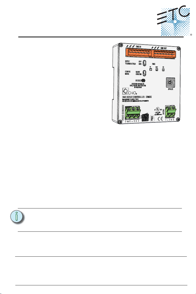
The DMX Scene Controller provides
control of dimmers and LED fixtures by
storing DMX output presets that can
be recalled as part of an Echo system
preset.
Features
The DMX Scene Controller is capable
of outputting DMX (a full universe of
512 addresses) and supports up to 32
presets.
Additional features include:
• DMX snapshot record
• Live playback of DMX levels stored in Echo presets
• Input DMX levels pass-through to the DMX output and supports HTP
with active internal “Arch” levels.
• Supports Off behavior for intensity and color zones
• DMX loss behavior reverts to current local control
The DMX Scene Controller is designed for installation on DIN rail and includes
a DMX cable preparation kit for proper DMX termination.
Custom Configuration
This document guides you through the installation and local configuration of
the Echo DMX Scene Controller. For more detailed information about the
custom configuration options available using EchoAccess, reference the
EchoAccess Mobile App integrated help system.
Note:
Corporate Headquarters Middleton, Wisconsin, USA Tel +608 831 4116 Service: (Americas) service@etcconnect.com
London, UK Tel +44 (0)20 8896 1000 Service: (UK) service@etceurope.com
Rome, IT Tel +39 (06) 32 111 683 Service: (UK) service@etceurope.com
Holzkirchen, DE Tel +49 (80 24) 47 00-0
Hong Kong Tel +852 2799 1220 Service: (Asia) service@etcasia.com
Web: www.etcconnect.com
Product information and specifications subject to change
7186M2106 Rev A Released 2016-02
DMX Scene Controller Page 1 of 7 Electronic Theatre Controls, Inc.
Settings made using EchoAccess are applied only when the
Config Mode switch is set to Custom. Reference Custom on
page 6.
Service: (DE) techserv-hoki@etcconnect.com
Copyright © 2016 ETC. All Rights Reserved.
. ETC intends this document to be provided in its entirety.
Page 2
ETC Installation Guide
DMX Scene Controller
Accessory Kits
ETC offers a Low Voltage DIN rail Cover Kit (ETC part number 7186A1218)
that allows installation of the DMX Scene Controller to a 4” (10.16cm)
junction box (provided by others). Contact ETC for ordering details.
Specification
Note:
For use with ETC Dimming and Relay products.
Installation should follow all local codes and standard
electrical practices.
Ambient Environment
For indoor, commercial controls use only. Supports plenum rating.
• Operating temperature 0-50°C, 5-95% non-condensing humidity.
Compliance
UL/cUL listed, supporting use in a plenum space
CE compliant with EN55103:2009 for professional lighting control
WEEE marked
FCC compliant for conducted and radiated emissions
Electrical Requirements
The DMX Scene Controller requires 24 Vdc (Class II) power, supplied by an
external 24 Vdc power supply. Termination for this connection is provided on
a two position terminal, labeled 24 Vdc, accepting 26-14 AWG (0.4 - 1.6mm
wires (typically a 16AWG black and red wire pair).
Note:
NEC Class 2 product are to be wired in accordance with
NEC Article 725 and local jurisdiction requirements.
2
)
All power and control wiring should be installed and
terminated by a qualified installer and should follow
standard wiring installation practices.
DMX Scene Controller Page 2 of 7 Electronic Theatre Controls, Inc.
Page 3

ETC Installation Guide
DMX Scene Controller
Control Signal Requirements
EchoConnect
The DMX Scene Controller requires EchoConnect, Belden 8471 (or equivalent)
plus one 14 AWG (2.5mm2) ESD ground wire, supporting control signal
between the device and the connected Echo system.
EchoConnect is a bidirectional protocol that uses one pair of wires (data+ and
data-). ETC recommends using Belden 8471 (or approved equal) Class II wire.
The total combined length of an EchoConnect wire run (using Belden 8471, or
equal) may not exceed 1,640 feet (500m).
DMX
The DMX Scene Controller is designed for communication with a DMX
controller, such as a DMX console for the DMX input, and DMX controlled
devices including dimmers and LED drivers for the DMX output. Cable
terminations are made to the 8 position removable pluggable connectors on
the DMX Scene Controller.
ETC recommends use of Belden 9729 (or equivalent) wiring for DMX control
wiring. ETC recommends a maximum length of the wire run at 1600’ (487 m).
A DMX cable preparation kit is provided to prepare the Belden 9729 (or
equivalent) cable before termination.
DMX Scene Controller Page 3 of 7 Electronic Theatre Controls, Inc.
Page 4

ETC Installation Guide
DMX Scene Controller
Installation
Install to DIN Rail
3
2
Step 1: Ensure the section of DIN rail to be used is mounted securely
according to the manufacturers requirements. DIN rail is
provided by others.
Step 2: Hook the bottom of the DMX Scene Controller under the
lower DIN rail as shown.
Step 3: Pivot the bridge up and depress until the top clip on the bridge
seats completely onto the DIN rail.
Connect Wiring
Connect EchoConnect
EchoConnect terminations require Belden 8471 (or equivalent) between the
EchoConnect bus and DMX Scene Controller, plus one 14 AWG (2.5mm2) ESD
ground wire.
Step 1: Strip 3/8” (9-10mm) of insulation from the bare end of the
Belden 8471 (or equivalent) wires and the ESD ground wire.
Step 2: Loosen the three screw terminals (ground, -, +) on the
EchoConnect terminals.
Step 3: Insert the data + wire (white is typical) into terminal 3
(identified with a + symbol), insert the data - wire (black is
typical) into terminal 2 (identified with a - symbol), and insert
the ground wire (green/yellow is typical) into terminal 1
(identified with a ground symbol).
Step 4: Secure the screws firmly onto each wire.
DMX Scene Controller Page 4 of 7 Electronic Theatre Controls, Inc.
Page 5

ETC Installation Guide
DMX Scene Controller
Connect DMX In and Out
Locate the provided DMX cable
preparation kit and follow the
From DMX source
DMX A
To DMX
controlled devices
provided instruction to prepare
the DMX cables, both input and
output, using Belden 9729 or
approved equivalent. Be aware
that cable other than Belden
9729 may have a different color
code for its wire pairs.
n/c
n/c
n/c
n/c
n/c
COM
Data + (Red)
Data - (Black)
12345678
Data + (Red)
Data - (Black)
n/c
n/c
n/c
n/c
n/c
Reference the illustration to the
right for DMX wire termination
to the 8 position screw terminal
connectors (provided). For best
DMX IN DMX OUT
DMX performance, twist the
wires together as close to the pluggable connector as possible.
Label each cable run accordingly and re-install the prepared connectors to the
appropriate receptacle on the controller.
Connect 24 Vdc
An external 24 Vdc (Class II) power supply is required to power the DMX Scene
Controller. Terminate to the DMX Scene Controller terminals labeled 24 Vdc.
Terminals accept 26-14 AWG (0.4 - 1.6mm2) wires (typically a 16AWG black
and red wire pair).
Step 1: Strip 9-10mm (3/8”) of insulation from the bare end of each
wire.
Step 2: Loosen the two 24 Vdc screw terminals.
Step 3: Insert the “negative -” wire (black wire typical) into
terminal 1 (identified with a - symbol), and insert the
“positive +” wire (red wire typical) into terminal 2 (identified
with a + symbol) of the 24 Vdc terminals.
Step 4: Secure the screws firmly onto each wire.
COM
12345678
Set Space
The DMX Scene Controller participates in an Echo system using the configured
Space, which is selectable using the rotary switch on the front of the unit.
Set the Space rotary switch to the desired Space number for this controller.
All devices that are in the same Space will share control of the connected Echo
stations and sensors.
DMX Scene Controller Page 5 of 7 Electronic Theatre Controls, Inc.
Page 6

ETC Installation Guide
DMX Scene Controller
Set Configuration Mode
The “Config Mode” switch allows selection between Basic and Custom
configurations of the DMX Scene Controller. Basic is the factory default
setting.
Basic
Set the switch to Basic configuration mode to apply the following behaviors to
the DMX Scene Controller:
• Preset snapshot record and recall for all 512 DMX addresses, for up to
32 presets.
• 2 second preset fade-time
• Zone patch data is not applied, therefore no zones will be individually
controllable.
• Space Raise/Lower, as well as any other space intensity adjustments, will
have no affect on any outputs.
Custom
Set the switch to Custom configuration mode to apply the settings that are
supported by EchoAccess.
Reference the EchoAccess Mobile Application integrated help system for
details about available configurable device parameters and actions available
on the DMX Scene Controller including: configurable preset fade times, zone
patch for intensity or color LED fixture control, and configuration of space
raise/lower commands to affect unpatched DMX addresses.
Set Input Termination
The “Input Termination” switch allows selection of DMX input termination
between Off and End. By factory default, this switch is set to End.
• Set the switch to Off when the DMX Scene Controller is not the last
DMX device in the wire run.
• Set the switch to END when the DMX Scene Controller is the last DMX
device in the wire run.
Reset Device
Using a ball point pen, press the [Reset] button to reset the DMX Scene
Controller, cycling power and restoring the device to normal operation.
Reset to Factory Defaults
Using a ball point pen, press and hold the [Reset] button for 10 seconds to
reset the DMX Scene Controller to factory defaults.
DMX Scene Controller Page 6 of 7 Electronic Theatre Controls, Inc.
Page 7

ETC Installation Guide
DMX Scene Controller
Power Up
Once the DMX Scene Controller is connected to the EchoConnect station bus
and power is applied, the power LED will indicate in blue.
When DMX is present on the Input connector the “DMX IN” LED indicates as
follows:
• green = valid DMX
• blinking red = error
• no indication = no DMX is present
Remove the Bridge from DIN
If for any reason you need to remove the DMX Scene Controller from the DIN
rail, follow these instructions.
Step 1: Disconnect all wiring and cap off as necessary.
Step 2: Insert a flat head screwdriver into the clip on top of the bridge,
slide it straight up, then pivot the top of the bridge off of the
DIN rail.
DMX Scene Controller Page 7 of 7 Electronic Theatre Controls, Inc.
 Loading...