

Page 1
ETC Installation Guide
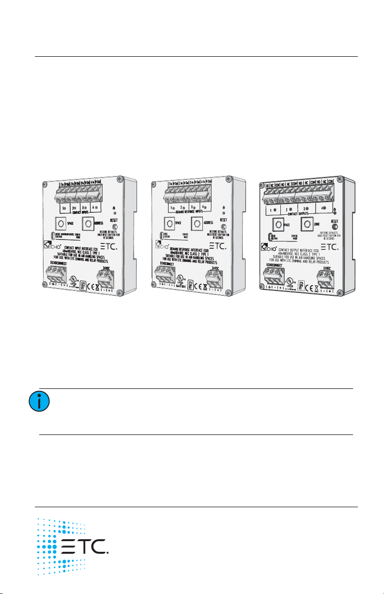
Contact Input Interface Demand Response Interface Contact Output Interface
Contact and Demand Response Interfaces
Overview
The Unison Echo® Contact and Demand Response Interfaces are DIN rail
mounted devices that are available in the following configurations:
• Input Interface - accepts four momentary or maintained closures to
trigger control actions within an Echo control system.
• Demand Response Interface - accepts four maintained closures to
trigger demand response within an Echo control system.
• Output Interface - provides four normally open or normally closed
output relays controlled by actions in the Echo control system.
Custom Configuration
This document guides you through the installation and basic local
configuration settings of the interface devices.
For more detailed information about custom configuration options available
using EchoAccess
®
, reference the EchoAccess Mobile App integrated help
system.
Note:
To use the configuration settings applied using
EchoAccess, the unit must be placed in Custom
configuration mode. Reference Set Configuration Mode.
Accessory Kit
ETC offers a Low Voltage DIN rail Cover Kit (ETC part number 7186A1218)
that allows installation of a Contact Interface to a 4” (10 cm) junction box
(provided by others). Contact ETC for ordering details.
Corporate Headquarters Middleton, Wisconsin, USA Tel +608 831 4116
Service (Americas)
London, UK Tel +44 (0)20 8896 1000 Service: (UK) service@etceurope.com
Rome, IT
Holzkirchen, DE Tel +49 (80 24) 47 00-0 Service: (DE) techserv-hoki@etcconnect.com
Hong Kong
Web: etcconnect.com
specifications subject to change.
7186M2144 Rev B Released 2018-04
service@etcconnect.com
Tel +39 (06) 32 111 683 Service: (UK) service@etceurope.com
Tel +852 2799 1220 Service: (Asia) service@etcasia.com
© 2018 Electronic Theatre Controls, Inc.
ETC intends this document to be provided in its entirety.
Product information and
Page 2

ETC Installation Guide
Contact and Demand Response Interfaces
Prepare for Installation
Note:
Installation should follow all local codes and standard
electrical practices.
Ambient Environment
For indoor, commercial controls use only. Supports plenum rating.
• Operating temperature 0-50°C, 0-95% non-condensing humidity.
Compliance
• UL/cUL listed, supporting use in a plenum space
• CE compliant
• WEEE marked
For use with ETC dimming and relay products.
Control Requirements
EchoConnect
Echo interface devices require EchoConnect®, Belden 8471 (or equivalent)
plus one ESD ground wire, supporting control signal between the device
and the connected Echo control system.
EchoConnect is a bidirectional protocol that uses one pair of wires (data+
and data-). ETC recommends using Belden 8471 (or approved equal) Class 2
wire.
The total combined length of an EchoConnect wire run (using Belden 8471,
or equal) may not exceed 1,640 feet (500 m).
Electrical Requirements
Echo interface devices require 24 VDC (Class 2) external power in addition
to EchoConnect requirements. This auxiliary power is provided to the input
connector by an external supply. The unit draws a maximum of 40mA
during normal operation.
This connection is provided on a two position terminal, labeled 24 VDC, and
accepts 24-12 AWG (0.2-4 mm
Note:
Echo Contact and Demand Response Interfaces Page 2 of 8 ETC
NEC Class 2 product are to be wired in accordance with
NEC Article 725 and local jurisdiction requirements.
All power and control wiring should be installed and
terminated by a qualified installer and should follow
standard wiring installation practices.
2
) wires (typically black and red wire pair).
Page 3
ETC Installation Guide
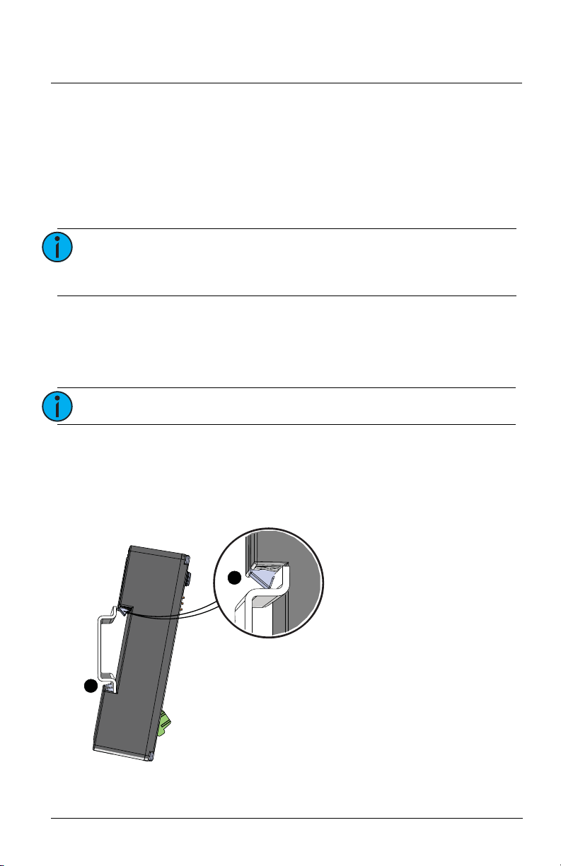
1: Ensure the section of DIN rail to be used is mounted
securely according to the manufacturer’s
requirements. DIN rail is provided by others.
2: Hook the bottom of the Echo interface under the lower
DIN rail as shown.
3: Pivot the interface up and depress until the top clip
seats completely onto the DIN rail.
Contact and Demand Response Interfaces
Input and Demand Response Interface Wire Terminations
The Input and Demand Response Interfaces provide four sets of terminals
(“In” and “V out”) for connection to a momentary (Input Interface only) or
maintained contact input. Terminals accept 24-12 AWG (0.2 mm
wire.
Each input supports wet or dry contact closures and includes a related
onboard LED to indicate contact status.
2
-4 mm2)
Note:
Output Interface Wire Terminations
The Contact Output Interface provides four sets of terminals (normally open
“N.O.”, normally closed “N.C.”, and common “COM”) for connection of
output relays. Terminals accept 24-12 AWG (0.2 mm
Note:
Each output includes a corresponding onboard LED to indicate the normally
open status of the relay.
Installation
Install to DIN rail
Input terminals accept 3 - 24 VDC, and support 2,000
feet (610 m) of 18 AWG (1 mm
2
) wire (round trip wire
to the device) when using 24 VDC.
2
- 4 mm2) wire.
Each output is rated for 2A at 30 VAC or 30 VDC.
3
2
Echo Contact and Demand Response Interfaces Page 3 of 8 ETC
Page 4

ETC Installation Guide
Contact and Demand Response Interfaces
Terminate Wiring
Connect Auxiliary 24 VDC
An external 24 VDC (Class 2) auxiliary power supply is required to power the
interface. Terminate to the interface terminals labeled 24 VDC. Terminals
accept 24-12 AWG (0.2-4 mm
wire pair).
1: Strip 3/8” (9-10 mm) of insulation from the end of each wire.
2: Loosen the two 24 VDC screw terminals.
3: Insert the negative voltage wire (black wire typical) into the terminal
labeled “-” and insert the positive voltage wire (red wire typical) into
terminal labeled “+”.
4: Secure the screws firmly onto each wire.
Connect EchoConnect
EchoConnect terminations accept 24-12 AWG (0.2-4 mm2) wires for Belden
8471 (or equivalent) between the EchoConnect bus and the Echo interface,
plus one ESD ground wire.
1: Strip 3/8” (9-10 mm) of insulation from the bare end of the Belden
8471 (or equivalent) wires and the ESD ground wire.
2: Loosen the three screw terminals (ground, -, +) on the EchoConnect
terminals.
3: Insert the data + wire (white is typical) into the terminal labeled “+”,
insert the data - wire (black is typical) into the terminal labeled “-”,
and insert the ground wire (green/yellow is typical) into the terminal
labeled .
4: Secure the screws firmly onto each wire.
2
) wires (typically a 16 AWG black and red
Connect Input Wiring (Input Interface and Demand Response)
Terminals accept 24-12 AWG (0.2-4 mm2).
Dry Contact Input
1: Strip 3/8” (9-10 mm) of insulation from each wire.
2: Loosen the two terminals (“In” and “V out”) for the contact input.
3: Insert one wire into each terminal then secure the screws firmly onto
each wire.
Wet Contact Input
For a wet contact input into the Input Interface, you must terminate to both
the “In” and the negative “-” terminal of the 24 VDC Auxiliary input.
The “V out” terminal will not be used for this termination.
1: Strip 3/8” (9-10 mm) of insulation from each wire.
Echo Contact and Demand Response Interfaces Page 4 of 8 ETC
Page 5

ETC Installation Guide
Contact and Demand Response Interfaces
2: Loosen the “In” terminal for the contact input and insert the positive
contact voltage wire.
3: Terminate the contact return wire into the negative “-” terminal of
the
24 VDC input. Alternative wiring termination methods may be
required to accommodate multiple terminations.
4: Secure the screws firmly onto each wire for all terminals.
Connect Output Wiring (Output Interface only)
Terminals accept 24-12 AWG (0.2-4 mm2)
1: Strip 3/8” (9-10 mm) of insulation from each wire.
2: Determine the type of output required, normally open (NO) or
normally closed (NC), then loosen the respective output and COM
terminals.
3: Insert the common wire into the “COM” terminal and the output
wire into the respective “NO” or “NC” terminal.
4: Secure the screws firmly onto each wire.
Set Configuration Mode
The configuration mode switch allows selection between Basic and Custom
configurations of the interface. Basic is the factory default setting.
Basic
Basic configuration mode applies the following default behaviors:
Input Interface:
Inputs control Presets 1-4 respectively, using momentary input mode where
the closure behaves similar to an Echo Inspire station.
• close / open event (push) executes a preset toggle
• holding the contact closed (hold) performs a space raise
• closing the closure twice (in rapid succession) performs a preset
toggle with 1/2 second override timing
Note:
Echo Contact and Demand Response Interfaces Page 5 of 8 ETC
Particularly when considering machine driven
applications, ETC recommends a minimum of 500 ms
between any input changes to ensure transitions are
reliably applied.
Page 6

ETC Installation Guide
Contact and Demand Response Interfaces
Demand Response Interface:
Activates Demand Response, affecting up four consecutive Echo Spaces,
starting with the interface Space rotary switch setting.
Example: Setting the Space switch to 3 results in control of Spaces 3, 4, 5,
and 6. A value higher than 13 will result in control of only Spaces 14, 15,
and 16.
Note:
Each Echo space can only have one assigned demand
response input.
Functionality:
• a closed contact means the designated space is in active Demand
Response state
• an open contact means Demand Response is inactive
Output Interface:
Relay outputs are controlled by Zones 1-4 respectively (when the Zone dial is
set to its default setting of 1). Changing the Zone dial will alter the starting
Zone. Reference the related Note on the bottom of page 7.
Note:
Functionality varies depending on whether the
normally open or normally closed contact terminal is
utilized. The default behaviors listed below are
assuming a normally open installation. The normally
closed contact provides inverted behavior, its status
always the opposite of the normally open contact.
• When the intensity of an assigned zone is non-zero the
corresponding relay output will be closed.
• When the intensity of an assigned zone is equal to zero the
corresponding relay will be open.
• By default, all odd numbered presets, when activated, will close all
relay outputs and all even numbered presets, when activated, will
open all relay outputs. This is true until the preset is re-recorded with
new values.
Custom
Custom configuration mode applies the following default behaviors until
changed using the EchoAccess Mobile App:
Input Interface
Inputs control Presets 1-4 respectively, using maintained input mode where:
• closing contact activates a preset
• opening a contact deactivates a preset
Echo Contact and Demand Response Interfaces Page 6 of 8 ETC
Page 7

ETC Installation Guide
Contact and Demand Response Interfaces
Demand Response Interface
Inputs control Spaces determined by settings applied in the EchoAccess
Mobile App.
Note:
Output Interface
Relay outputs are controlled by the status of Presets 1-4 respectively.
• When the status of an assigned preset is active, the corresponding
relay output will be closed.
• When the status of an assigned preset is inactive, the corresponding
relay will be open.
Aside from the default behaviors when the configuration mode switch set
to Custom, complete configuration of the Output Interface is supported by
the EchoAccess Mobile App. For detailed information about custom
configuration options available using EchoAccess, reference the EchoAccess
Mobile App integrated help system.
Each Echo space can only have one assigned demand
response input.
Set Space and Address / Zone Start
Interface devices participate in an Echo control system using the configured
Space and Address / Zone which are selectable using the rotary switches on
the front of the unit.
By default, these switches are set to Space 1, Address / Zone 1.
1: Set the Space for this device (1 through 16 available). All control
inputs from the connected stations, sensors, and other controls are
shared by all devices within the selected space. This setting applies
regardless of the selected configuration mode (Basic or Custom).
Note:
2: Set the Address / Zone:
• For an Input Interface, set the Address (1 through 16 available)
Note:
Echo Contact and Demand Response Interfaces Page 7 of 8 ETC
For the Demand Response Interface, setting the Space
address determines the four consecutive spaces that
will be controlled. A value higher than 13 will result in
control of only Spaces 14, 15, and 16.
which identifies the device in the selected space. This setting
always applies.
Do not duplicate a device address within the same
space.
Page 8

ETC Installation Guide
Contact and Demand Response Interfaces
• For an Output Interface, set the Zone number (1 through 16 available)
for the first output on the interface. The remaining outputs will be
assigned consecutive zone numbers. The zone number does not
apply while in Custom configuration mode.
Note:
When setting the first zone number, be careful to
allow enough in the range for all outputs in the
interface. For example, if you set the first zone to
address 15, the remaining output contacts on the
controller will be assigned to and respond as Zone 16.
Power Up
All EchoConnect terminations in the system must be made before applying
power to the system and interface. When the interface is powered up, the
power LED will indicate in blue.
LED States
Input and Demand Response Interface
When a contact is closed, the related status LED will illuminate.
Output Interface
When the normally open contact is closed, the corresponding status LED will
illuminate.
Reset Device
Using a ball point pen, press the [Reset] button to reset the interface, cycling
power and restoring the device to normal operation.
Reset to Factory Defaults
Using a ball point pen, press the [Reset] button for ten seconds to reset the
interface to factory defaults. The power LED will flash when the device has
been restored to its factory defaults.
Remove the Interface from DIN rail
If for any reason you need to remove the interface from the DIN rail, follow
these instructions:
1: Shut off power from the unit.
2: Label, then disconnect all wiring and cap off as necessary.
3: Insert a flat blade screwdriver into the clip on top of the interface,
slide the unit straight up, then pivot the top edge off the DIN rail.
Echo Contact and Demand Response Interfaces Page 8 of 8 ETC
 Loading...