

Page 1
ETC® Installation Guide
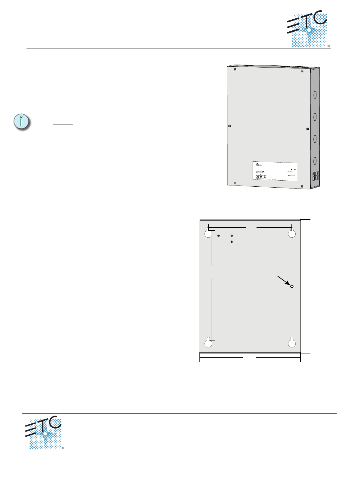
The Echo Wall Mount Station Power Supply (E-SPM-WM) is
designed for use with the Echo control system to supply power
for up to 16 Echo control stations on the topology-free Echo
control network.
Note:
If you are using Cat5 (or Cat5e) wiring, an
external Echo Cat5 Termination Box (is
required. Contact ETC for ordering details.
Control wiring instructions between the
termination box and this Wall Mount Station
Power Supply will be provided with the Cat5
termination installation instructions.
10.5”
267mm
14”
356mm
insert seismic
condition screw
here
11. 5”
292mm
8.7”
221mm
3.15” deep
80mm
as viewed from the back panel
Unison Echo® Wall Mount Station Power Supply
Overview
Wall Mount Enclosure Installation
Mount the Unit to the Wall
Step 1: Remove the front cover of the unit to
reveal the four mounting keyholes
from inside the unit.
Step 2: Align the unit to the wall and mark the
mounting keyholes. Alternatively, use
the measured keyhole dimensions
located in the graphic (right) to mark
the hole locations for the mounting
hardware.
Step 3: Drill the holes and install the mounting
hardware.
• Mounting hardware is not
supplied.
Step 4: Attach the unit to the mounting
Step 5: Insert a screw into the provided wall
Corporate Headquarters
London, UK
Rome, IT
Holzkirchen, DE
Hong Kong Rm 1801, 18/F, Tower 1 Phase 1, Enterprise Square, 9 Sheung Yuet Road, Kowloon Bay, Kowloon, Hong Kong Tel +852 2799 1220 Fax +852 2799 9325
Service:
Web:
www.etcconnect.com
7186M2100
• Expose at least 1” (25mm) of
threads for mounting the unit.
hardware, where the back side of the
unit is flush to the wall, then tighten the
mounting hardware.
anchor point, located between the left
side mounting keyholes of the unit. Populating this hole with a screw provides additional
security that the unit will not fall from the wall during a seismic condition.
Unit 26-28, Victoria Industrial Estate, Victoria Road, London W3 6UU, UK Tel +44 (0)20 8896 1000 Fax +44 (0)20 8896 2000
Via Pieve Torina, 48, 00156 Rome, Italy Tel +39 (06) 32 111 683 Fax +44 (0) 20 8752 8486
(Americas) service@etcconnect.com
Rev A Released 2014-06
3031 Pleasant View Road, P.O. Box 620979, Middleton, Wisconsin 53562-0979 USA Tel +608 831 4116 Fax +608 836 1736
Ohmstrasse 3, 83607 Holzkirchen, Germany Tel +49 (80 24) 47 00-0 Fax +49 (80 24) 47 00-3 00
Copyright © 2014 ETC. All Rights Reserved. Product information and specifications subject to change.
(UK) service@etceurope.com (DE) techserv-hoki@etcconnect.com
ETC intends this document to be provided in its entirety.
(Asia) service@etcasia.com
Wall Mount Station Power Supply Page 1 of 3 Electronic Theatre Controls, Inc.
Page 2
ETC Installation Guide
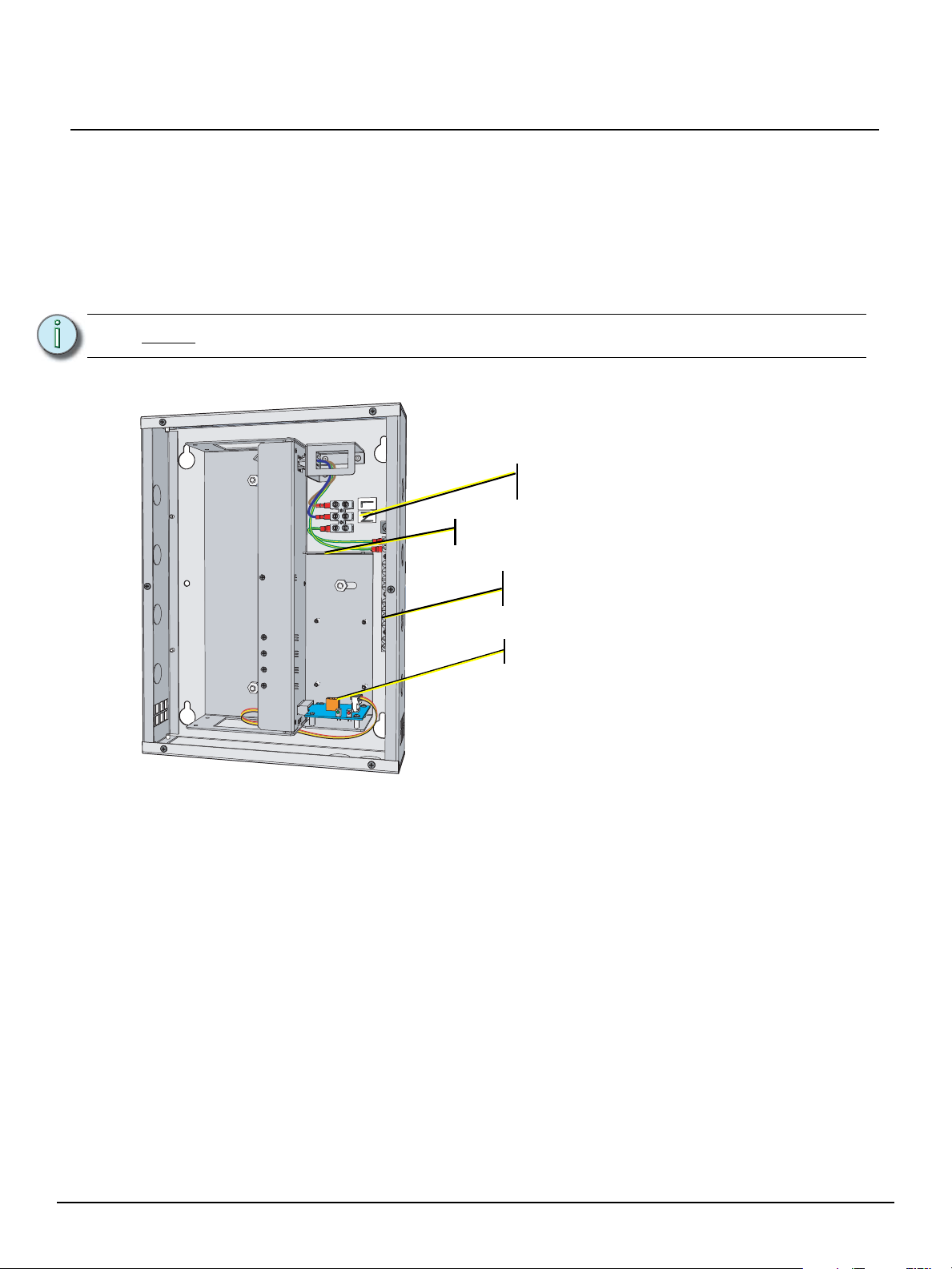
AC Input - 2 wire plus
Protective Earth (ground)
ESD Ground terminals - Echo station
ESD ground wires terminate here
Control wiring - Belden 8471
voltage barrier
Wall Mount Station Power Supply
Rough-In Conduit and Wiring
Knockouts are provided on top and bottom for conduit access into the unit. All wiring terminations are
accessible from the front of the unit with the cover removed.
Required terminations include -
• A single phase 115 VAC, 230 VAC, or 240 VAC power input (two wire) which terminates to the
power input terminal block, plus a ground wire which terminates to the ground bar screw terminal.
• A single run of Belden 8471 plus one 14 AWG (1.6mm) Echo station ESD ground wire.
Note:
Terminate Wiring
All low voltage control cables must run in separate conduit from power wires.
Connect Power
Supply a single phase of 115 VAC or 230/240 VAC (2 wire plus ground) to the AC input terminals.
Step 1: Connect the Line (Hot) wire to the terminal labeled “L”.
Step 2: Connect the Neutral wire to the terminal labeled “N”.
Step 3: Connect the Protective Earth (ground) wire to the ground terminal.
Wall Mount Station Power Supply Page 2 of 3 Electronic Theatre Controls, Inc.
Page 3
ETC Installation Guide
Wall Mount Station Power Supply
Connect Control Wiring
Termination is available for the EchoConnect station communication bus (Belden 8471 or approved
equal). EchoConnect requires one pair of wires (data+ and data -). The total combined length of an
EchoConnect wire run cannot exceed 1,640 feet (500m), with a maximum distance of 1,313 feet (400m)
between any two devices.
Note:
Step 1: Remove the two pin screw terminal connector from the termination board.
Step 2: Connect the Belden 8471 wires to the screw terminal connector. This connection is
polarity dependent. Refer to the connector label for notation of “data +” and “data -”.
• Connect the white wire to the data + terminal.
• Connect the black wire to the data - terminal.
Step 3: Connect one 14 AWG (1.6mm) Echo station ESD ground wire (Protective Earth) to the
provided ESD ground terminals inside the unit.
Final Installation
Step 1: Replace the front cover to the unit.
Step 2: Supply power to the unit.
Step 3: Check the front panel status indicators for faults.
Status Indicators
When power is applied, the Power LED located on the front panel illuminates green.
If a fault is discovered in the control wiring, the Power LED goes out and the Fault LED illuminates red.
This condition typically means that the station wiring has a fault; however it could mean a connected
device is having an issue.
All low voltage control cables must run in separate conduit from power wires. To
maintain the integrity of the voltage separation, a voltage barrier is provided in the unit
to separate all low voltage wiring from the AC input.
Note:
Wall Mount Station Power Supply Page 3 of 3 Electronic Theatre Controls, Inc.
A qualified technician should inspect the system wire and terminations first, then
proceed to disconnecting devices, troubleshooting the fault and correcting it. The
power supply will update the fault indicators automatically when the fault condition is
cleared.
 Loading...