

Page 1
ETC Installation Guide
The Lockout station is designed for use with any
EchoConnect-enabled system including Echo Zone
Controllers, Echo Relay Panels, Sensor3 and Unison DRd
with Echo ACP.
Unison® Echo Lockout Station
Overview
Echo Lockout station enables security for stations within a space, preventing
unwanted control-activation from all stations within the space while the keyed
lockout is enabled.
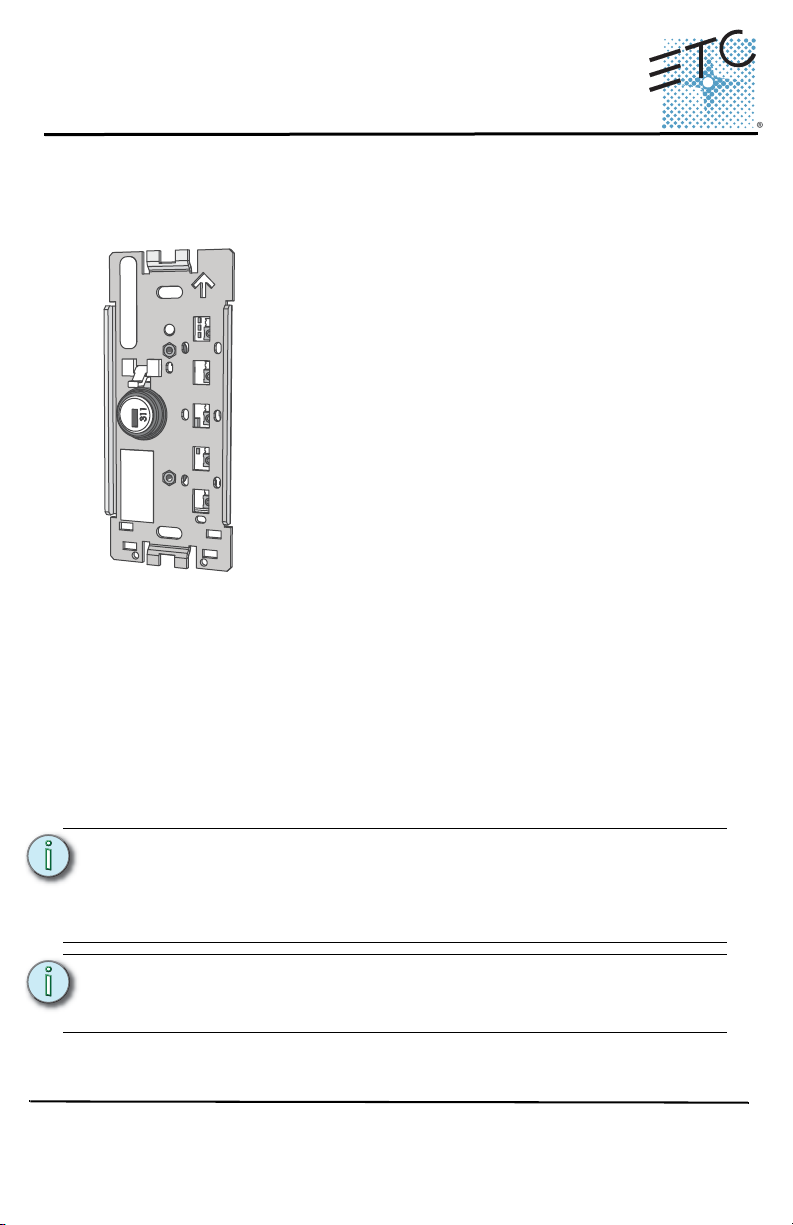
Prepare for Installation
Echo Lockout stations ship with station electronics, faceplate, termination kit,
(2) keys, and installation hardware. The station may be installed into a standard
back box (provided by others) or surface mounted back box (sold separately
and available from ETC).
Lockout stations connect to the EchoConnect station communication bus.
EchoConnect is a bidirectional protocol that uses one pair of wires (data+ and
data-) for both data and power. ETC recommends using Belden 8471 (or
approved equal) Class II wire. The total combined length of an EchoConnect
wire run may not exceed 1,640 feet (500m).
Note:
All control wiring should be installed and terminated by a qualified
installer and should follow standard wiring installation practices.
Leave approximately 10 inches (254mm) of wiring in the back box
for connection and to allow slack for future service needs.
Note:
ETC requires that all stations be grounded. Pull an additional
14 AWG (1.5mm2) wire for grounding when control wires are not
installed in grounded metal conduit.
Environmental
• Indoor installation - 0-50deg C, 5-95% non-condensing humidity
Corporate Headquarters
London, UK
Unit 26-28, Victoria Industrial Estate, Victoria Road, London W3 6UU, UK Tel +44 (0)20 8896 1000 Fax +44 (0)20 8896 2000
Rome, IT
Via Pieve Torina, 48, 00156 Rome, Italy Tel +39 (06) 32 111 683 Fax +44 (0)20 8752 8486
Holzkirchen, DE
Hong Kong Rm 1801, 18/F, Tower 1 Phase 1, Enterprise Square, 9 Sheung Yuet Road, Kowloon Bay, Kowloon, Hong Kong Tel +852 2799 1220
Service:
(Americas) service@etcconnect.com
Web:
www.etcconnect.com
7140M2120
3031 Pleasant View Road, P.O. Box 620979, Middleton, Wisconsin 53562-0979 USA Tel +608 831 4116 Fax +608 836 1736
Ohmstrasse 3, 83607 Holzkirchen, Germany Tel +49 (80 24) 47 00-0 Fax +49 (80 24) 47 00-3 00
Rev A Released 2014-08 ETC intends this document to be provided in its entirety.
Copyright © 2014 ETC. All Rights Reserved. Product information and specifications subject to change.
(UK) service@etceurope.com (DE) techserv-hoki@etcconnect.com
(Asia) service@etcasia.com
Page 2
ETC Installation Guide
Space
Address
Echo™ Lockout Station
Installation
Installation should follow all local codes and standard electrical practices. The
back box (provided by others) should be installed level and square for best
results. Ensure that the back box is clean and free of obstructions and that all
wiring is installed correctly and in accordance with local codes.
Lockout stations ship with a termination kit for use with Belden 8471 (or
equivalent wire) and contains a power pigtail, a ground wire pigtail, spacers,
and all required wire termination connectors for installation.
Note:
When using Category5 (or equivalent) cable on the EchoConnect
communication bus, please note the following:
- Not all topologies are supported using Cat5; careful planning is
required to ensure the proper termination kits are available and
the wire is pulled appropriately.
- Cat5 wiring may be terminated using an EchoConnect Cat5
Station Termination Kit and must be installed using a bus
topology. Refer to the installation guide that is provided with the
Cat5 Station Termination Kit (7186A1207) for information to
terminate Cat5 wiring.
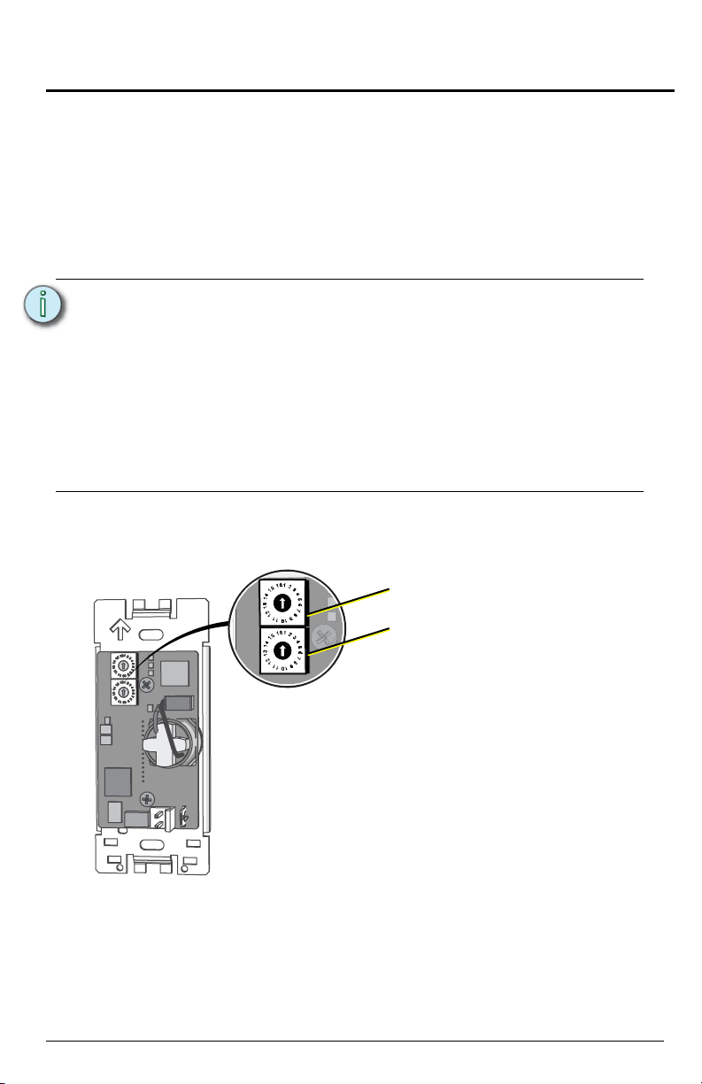
Assign the Station Address and Space
Echo Lockout station includes a set of rotary switches that determine space
assignment and station address.
Echo™ Lockout Station Page 2 of 6
Page 3

ETC Installation Guide
Ground spade
Data connector
Echo™ Lockout Station
Rotary Switch Assignments
Each station must be set to a unique station address for the assigned space.
By default, these switches are set to Space 1, Station Address 1. Commands
are shared by all devices within a space.
Step 1: Set the Space rotary switch to the desired number (1 thru 16) for the
space you want the station to provide lockout.
Step 2: Set the Address rotary switch to the desired address (1 thru 16) for the
station identification in the selected Space.
Connect the Wiring
Step 1: Pull all required wiring (data+, data-) into the back box. As needed, pull
an additional ESD ground wire (required only when the station is not
installed in grounded metal conduit).
Note:
Step 2: Connect station ESD ground wire pigtail.
a: Strip 3/8” (9-10mm) of insulation from the ends of the station ground wire
pigtail, provided in the termination kit, and the incoming ground wire to
the grounded metal back box.
b: Use one WAGO connector, provided in the termination kit, to connect
the station ESD ground pigtail and the incoming ground. For systems
using grounded metal conduit, connect the ground pigtail to the metal
back box ground location.
c: Install the ESD ground wire pigtail Faston connector to the spade
terminal on the station electronics.
A ground connection (14 AWG) is required between every
station and back box, even when installed with grounded
metal conduit.
Page 3 of 6 Echo™ Lockout Station
Page 4

ETC Installation Guide
Topology of a
single station
installation
Topology of
multiple stations
installed in series
Installed control wire
Pigtail wire
Installed control wire
Installed wire to next station
Pigtail wire
Echo™ Lockout Station
Step 3: Terminate and connect EchoConnect wires. EchoConnect is topology
free, you may install the wires in any combination of bus, star, loop, or
home-run.
a: Strip 3/8” (9-10mm) from the ends of each power pigtail wire, provided
in the termination kit, and the installed control wires.
b: Use one WAGO connector, provided in the termination kit, to connect
the power pigtail and the installed control wires. Open the terminal
levers on the WAGO connector and insert the installed (typically black)
Belden 8471 wire and the black lead from the power pigtail into the
terminals. Then close the levers.
c: Repeat for the installed (typically white) Belden 8471 power wires and
the remaining white wire from the power pigtail using a new WAGO
connector.
d: Install the two pin connector from the power pigtail to the mating
receptacle on the station electronics.
Echo™ Lockout Station Page 4 of 6
Page 5

ETC Installation Guide
Echo™ Lockout Station
Installing the Station into the Back Box
Spacers are provided to help position the station and cover flush with the wall
in flush mount applications. The spacers are not used with surface mount back
boxes.
Step 1: Insert the station electronics and wiring into the back box. The arrow
on the mounting plate must point up.
Step 2: Use receptacle spacers as needed to provide a flush mounted station.
a: Fold the spacer in a zig-zag fashion and press the stack together to
achieve the thickness needed to fill the gap between the station, wall
surface, and the back box.
b: Cut off and discard the excess.
c: Place the stack between the station electronics and the flush mounted
back box.
Step 3: Secure the station electronics in place using the two screws provided.
If using spacers, insert the screws through the spacers as well.
Page 5 of 6 Echo™ Lockout Station
Page 6

ETC Installation Guide
Echo™ Lockout Station
Installing the Faceplate
The faceplate is secured to the station with two magnets that are located on the
bottom edge of the faceplate.
Step 1: Align the top of the faceplate approximately 20 degrees to the station.
Step 2: Hook the top of the faceplate on the tabs located on the top of the
station electronics assembly. To ensure the faceplate is hooked
properly on the top hook, wiggle it slightly side to side while the bottom
is angled about 20 degrees from the wall.
Step 3: Swing the bottom of the faceplate down until the magnets engage.
Step 4: If the faceplate does not fully attach, wiggle the bottom of the plate until
the magnets are seated properly to the station and the faceplate is
secure.
Service
If you have any difficulties installing your system or with system startup please
contact ETC Technical Services at the office nearest you. ETC contact
information is located at the bottom of page 1.
Echo™ Lockout Station Page 6 of 6
 Loading...