

Page 1
ETC Installation Guide
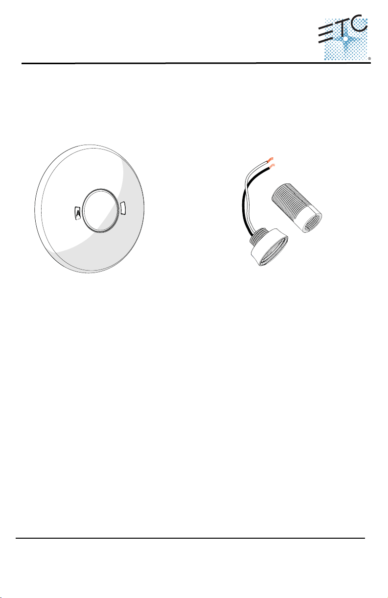
Light Sensor Head
with Controller
Thread
extender
Light Sensor
Head
Unison® Echo Light Sensor
Overview
The Echo Light Sensor provides light level measurement and lighting control
for the connected Echo control system. The Echo Light Sensor measures
lighting conditions to maintain a programmed lighting output in both dimmed
and switched systems.
Light Sensors are available in three models:
• E-LS - Light Sensor Head with Controller
• E-LSC - Light Sensor Controller Only
• E-LSH - Light Sensor Head Only
Each controller supports one or two Light Sensor Heads and is available in
white or black finish.
A Light Sensor Head may be installed within the controller or installed remotely,
using up to 1,000 feet (304m) of 16 AWG wire per controller. When using a pair
of Light Sensor Heads, both sensors transmit their light readings to a single
Light Sensor Controller. The controller averages the levels and uses them to
control lighting within the space.
Wire Specification
Controller
The Light Sensor Controller utilizes EchoConnect for power and for data
communications with an Echo Control System. EchoConnect is a bidirectional
protocol that uses one pair of wires (data + and data -) for both data and power.
ETC recommends using Belden 8471 (or approved equal) Class II wire. The
total combined length of an EchoConnect wire run (using Belden 8471 or
equal) may not exceed 1,640 feet (500m).
Corporate Headquarters
London, UK
Unit 26-28, Victoria Industrial Estate, Victoria Road, London W3 6UU, UK Tel +44 (0)20 8896 1000 Fax +44 (0)20 8896 2000
Rome, IT
Via Pieve Torina, 48, 00156 Rome, Italy Tel +39 (06) 32 111 683 Fax +44 (0)20 8752 8486
Holzkirchen, DE
Hong Kong Rm 1801, 18/F, Tower 1 Phase 1, Enterprise Square, 9 Sheung Yuet Road, Kowloon Bay, Kowloon, Hong Kong Tel +852 2799 1220
Service:
(Americas) service@etcconnect.com
Web:
www.etcconnect.com
7186M2170
3031 Pleasant View Road, P.O. Box 620979, Middleton, Wisconsin 53562-0979 USA Tel +608 831 4116 Fax +608 836 1736
Ohmstrasse 3, 83607 Holzkirchen, Germany Tel +49 (80 24) 47 00-0 Fax +49 (80 24) 47 00-3 00
(UK) service@etceurope.com (DE) techserv-hoki@etcconnect.com
Rev A Released 2014-08 ETC intends this document to be provided in its entirety.
Copyright © 2014 ETC. All Rights Reserved. Product information and specifications subject to change.
(Asia) service@etcasia.com
Page 2

ETC Installation Guide
Echo™ Light Sensor
Note:
Note:
Note:
All control wiring should be installed and terminated by a qualified
installer and should follow standard wiring installation practices.
Leave approximately 10 inches (254mm) of wiring in the back box
to allow slack for future service needs.
ETC requires that all sensors be grounded. Pull an additional 14
AWG (1.5mm2) wire for grounding when control wires are not
installed in grounded metal conduit.
When using Category5 (or equivalent) cable on the EchoConnect
communication bus, please note the following:
- Not all topologies are supported using Cat5; careful planning is
required to ensure the proper termination kits are available and
the wire is pulled appropriately.
- Cat5 wiring must be terminated using EchoConnect Cat5
Termination Kit, and it must be installed using a bus topology.
Refer to the installation guide provided with the Cat5 Termination
Kit (7186A1207) for information to terminate Cat5 wiring.
Remoting the Light Sensor Head
The Light Sensor Controller provides termination for up to two remote Light
Sensor Heads. Each Light Sensor Head must be separately wired to the
controller using no more than 1000 feet (304m) of 16 AWG wire total per
controller. These wire runs must remain separate from EchoConnect wiring.
ETC recommends using Belden 8471 (or equivalent) wire.
Installation Environment
The Light Sensor Controller is intended for installation to a finished ceiling
surface, soft ceiling tile, attached to a round junction box or single-gang RACO
junction box. The controller operates in ambient temperatures of 0°C to 70°C,
non-condensing humidity.
The Light Sensor Head can be mounted directly into the controller, installed to
a 1/2” conduit knockout, or installed into a soft ceiling tile using the provided
thread extender. The Light Sensor Head can be installed outdoors when
mounted to a weatherproof enclosure. The sensor in this weatherproof
installation scenario operates in ambient temperatures of -25°C to 70°C.
Echo Light Sensor Installation Guide Page 2 of 12
Page 3
ETC Installation Guide
Echo™ Light Sensor
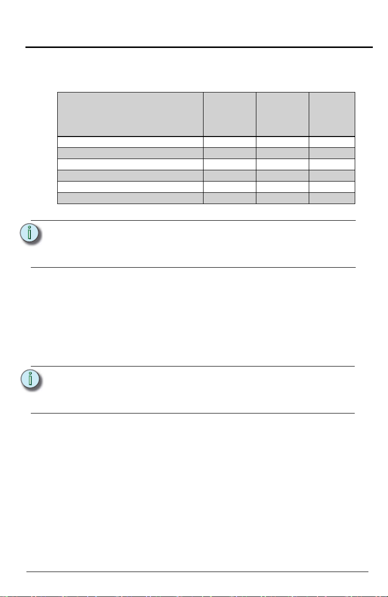
Parts and Supplies
The following parts and supplies are included with the specific Light Sensor
assembly ordered:
Light Sensor
Parts and Supplies
Soft ceiling tile adaptor XX
EchoConnect and ground wire pigtails X X
Light Sensor Head thread extender XX
1 each nuts and washers 3/4” and 1” X X
2 each screws 6-32 x 3/4” and 1 3/4” XX
Blank sensor head X X
Note:
- Follow all local code requirements for terminating wire.
- Use appropriately sized wire nuts (not provided) to secure each
termination.
Head with
Controller
(E-LS)
Light Sensor
Head
(E-LSH)
Light
Sensor
Controller
(E-LSC)
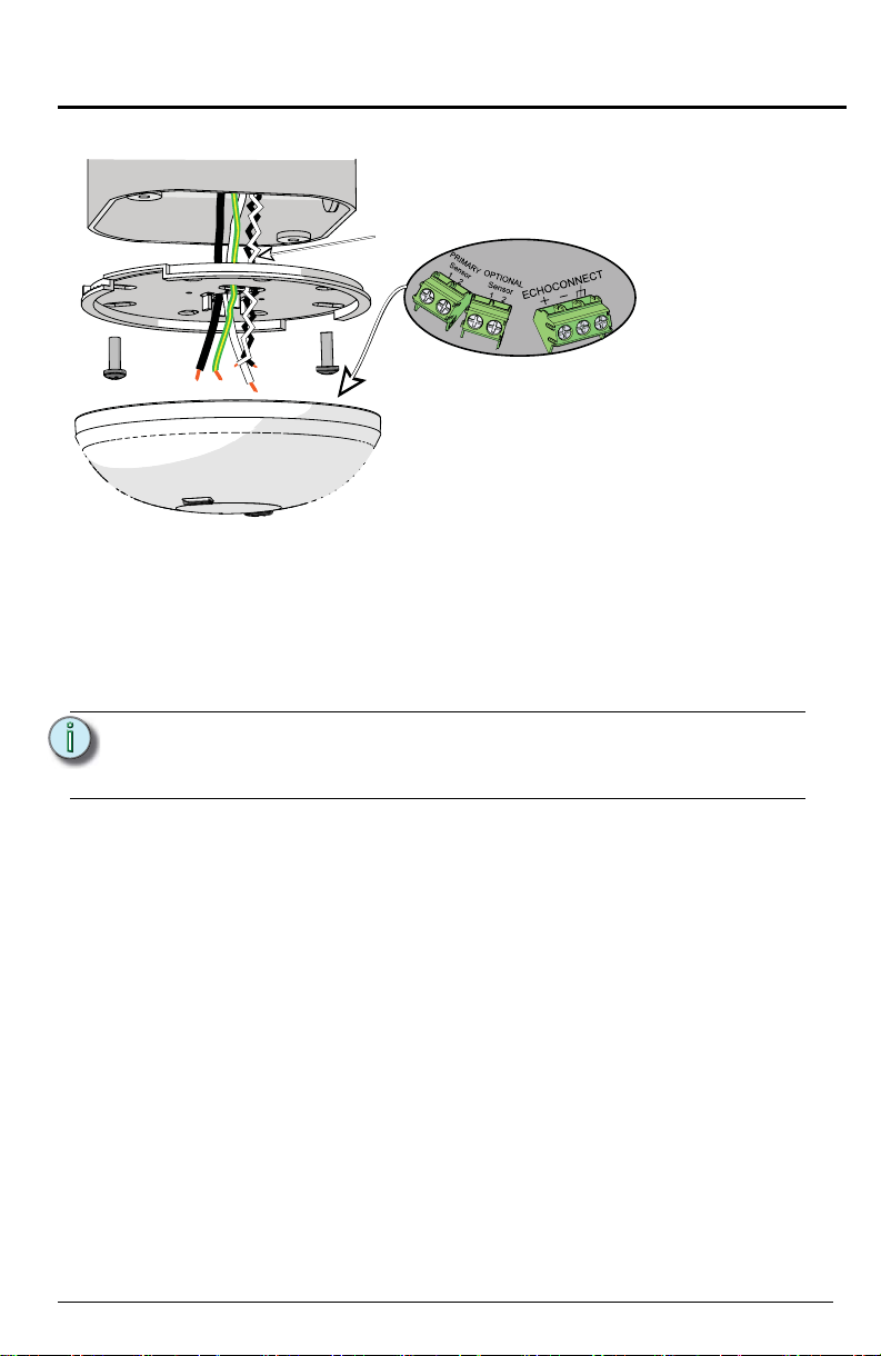
Installation
The Light Sensor Controller is provided with a twist-lock mounting plate that
can be mounted to a finished ceiling, junction box, or soft ceiling tile. Determine
the installation method and follow the specific instructions detailed.
• Install in Junction Box on page 4
• Soft Ceiling Tile Installation on page 6
• Installing the Light Sensor Heads Remotely (optional) on page 7
Note:
The EchoConnect pigtail is only required when the sensor and
controller are installed in series with other sensors. If you are not
continuing the data run, direct termination is recommended on
the sensor control board.
Page 3 of 12 Echo Light Sensor Installation Guide
Page 4
ETC Installation Guide
Terminate
wires here
Optional
sensor wires
Termination is available at the Controller for the
EchoConnect communication bus and up to two
Light Sensor Heads. Flexibility is provided with regards
to how the Light Sensor Head(s) is installed. You can
install a Light Sensor Head at the controller, or you can
install up to two Light Sensor Heads remotely.
Echo™ Light Sensor
Install in Junction Box
Step 1: Pull Belden 8471 (or equivalent) and 14 AWG (2.5mm2) ground wire to
the junction box.
Step 2: If you are installing the controller in series (continuing the data run)
to other sensors, sensor controllers, or stations, use the provided
EchoConnect pigtail and ESD ground pigtail to make the terminations.
If you are not continuing the data run, the pigtails are not required,
proceed to Step 3.
Note:
Primary Sensor and Optional Sensor wires should terminate
directly to the terminals located on the controller. See “Installing
the Light Sensor Heads Remotely (optional)” on page 7.
a: Strip each wire to the appropriate length, depending on the wire nut
or other termination used (wire nuts are not provided).
b: Twist the data - (typically black) EchoConnect wire, the black lead
from the EchoConnect pigtail, and any continuing EchoConnect
(typically black) wire together and secure with the wire nut.
c: Repeat the above steps for the data + (typically white)
EchoConnect wires, and for the ESD ground wires.
Step 3: If you are installing the Primary and/or Optional (second) Light
Sensor Head remotely from the controller, reference Installing the
Light Sensor Heads Remotely (optional) on page 7, then return to
these instructions. If you are not remoting a Light Sensor Head,
proceed to Step 4.
Echo Light Sensor Installation Guide Page 4 of 12
Page 5

ETC Installation Guide
Echo™ Light Sensor
Step 4: Orient the smooth side of the mounting plate to the junction box. Pull
the following wires from the junction box through the provided holes of
the mounting plate:
• EchoConnect bus wires or EchoConnect pigtail and ESD ground wires
depending on the installation.
• Remote Light Sensor Head wires (if remotely mounting Light Sensor
Heads).
Step 5: Secure the mounting plate to the junction box using the screws
provided (both short and long screws are included for convenience).
Step 6: Strip each wire 5/16” (8mm) and terminate the EchoConnect (white
and black wires) and ground wire (green/yellow) to the EchoConnect
terminal block located on the sensor controller. Torque each
termination to 3.1-3.5 in-lb.
a: Terminate the white incoming wire to the data + terminal.
b: Terminate the black incoming wire to the data - terminal.
c: Terminate the green/yellow (ground) wire to the labeled ground
terminal.
Step 7: To terminate remote Light Sensor Heads, See “Terminating Remote
Light Sensor Head Control Wiring” on page 8.
Page 5 of 12 Echo Light Sensor Installation Guide
Page 6

ETC Installation Guide
Poke the adapter through the ceiling tile, then bend
it over for a secure fit.
EchoConnect pigtail
and connectors
(optional use)
Terminate
wires here
Optional
sensor wires
soft ceiling
tile adapter
Echo™ Light Sensor
Soft Ceiling Tile Installation
Step 1: Pull the Belden 8471 (or equivalent) and 14 AWG (2.5mm2) ground
wire to the installation location.
Step 2: If you are installing the sensor in series (continuing the data run) to
other sensors, sensor controllers, or stations, use the provided
EchoConnect pigtail and ESD ground pigtail to make the terminations.
If you are not continuing the data run, the pigtails are not required,
proceed to Step 3.
a: Strip each wire to the appropriate length, depending on the wire nut
or other termination used (wire nuts are not provided).
b: Twist the data - (typically black) EchoConnect wire, the black lead
from the EchoConnect pigtail, and any continuing EchoConnect
(typically black) wire together and secure with the wire nut
c: Repeat the above steps for the data + (typically white)
EchoConnect wires, and for the ESD ground wires.
Step 3: If you are installing the primary and/or optional (second) Light
Sensor Head remotely from the controller, reference Installing the
Light Sensor Heads Remotely (optional) on page 7, then return to
these instructions. If you are not remoting a Light Sensor Head,
proceed to Step 4.
Step 4: Create a hole for wire pass-through in the ceiling tile by poking through
the center hole or oblong hole of the mounting plate, then pull the wires
through.
Echo Light Sensor Installation Guide Page 6 of 12
Page 7

ETC Installation Guide
Installed with
thread extender
Installed without extender
Two Light Sensor Heads may be
connected to the controller and
installed remotely.
Each Light Sensor Head must be
separately wired to the controller using
no more than 1000 feet (304m) of 16
AWG wire total per controller. These
wire runs must remain separate from
EchoConnect wiring. ETC
recommends using Belden 8471 (or
equivalent) wire.
Echo™ Light Sensor
Step 5: Orient the smooth side of the mounting plate to the ceiling tile. Pull the
following wires from the junction box through the provided holes of the
mounting plate:
• EchoConnect bus wires or EchoConnect pigtail and ESD ground wires
depending on the installation.
• Remote Light Sensor Head wires (if remotely mounting Light Sensor
Heads).
Step 6: Align and insert the soft ceiling tile adapter through the holes provided
on the mounting plate, poke the tines of the adapter through the ceiling
tile, then bend each tine over in opposite directions for a secure fit on
the back side of the ceiling tile.
Step 7: Strip each wire 5/16” (8mm) and terminate the EchoConnect (white
and black wires) and ground wire (green/yellow) to the EchoConnect
terminal block located on the sensor controller. Torque each
termination to 3.1-3.5 in-lb.
a: Terminate the white incoming wire to the data + terminal.
b: Terminate the black incoming wire to the data - terminal.
c: Terminate the green/yellow (ground) wire to the labeled ground
terminal.
Installing the Light Sensor Heads Remotely (optional)
Step 1: Prepare a hole in the Sensor Head installation location (3/4” hole
Step 2: Run Belden 8471 (or equivalent) between the controller and the Light
Step 3: For a Soft ceiling tile installation, pull the Light Sensor Head wire
Step 4: Insert the Light Sensor Head through the prepared installation
without adapter or 1” with adapter).
Sensor Head installation location.
leads through the thread extender, then attach the thread extender
onto the Light Sensor Head.
location. This should be done from the finished side of the installation
location to the unfinished side (ceiling).
Page 7 of 12 Echo Light Sensor Installation Guide
Page 8

ETC Installation Guide
Rotary Switch Assignments
Two rotary switches on the rear panel of the
sensor controller provide for Space and
Address assignment.
By default, these switches are set to Space 1,
Address 1. Each sensor and station in a space
must have a unique address setting and
commands are shared by all devices within a
space.
Echo™ Light Sensor
Step 5: Thread the appropriate washer and nut (two sizes included) onto either
the Light Sensor Head or the extension adaptor (if used), securing it in
place.
Terminating Remote Light Sensor Head Control Wiring
Termination is available at the Controller for up to two Light Sensor Heads
(labeled “Primary Sensor” and “Optional Sensor”). When remote Light Sensor
Heads are installed, follow these instructions to terminate the control wiring at
both the Light Sensor Head and the Controller.
Step 1: Terminate the incoming wire from the Controller to the Light Sensor
Step 2: Terminate the incoming wire pairs from the remote Light Sensor
Head leads using wire nuts or other wire termination (not provided).
a: Strip each wire to the appropriate length, depending on the wire nut
or other wire termination used (wire nuts are not provided).
b: Twist the installed (typically black) Belden 8471 incoming wire and
the black lead from the Light Sensor Head together and secure
using a wire nut or other wire termination.
c: Repeat for the installed (typically white) Belden 8471 wire and
remaining wire lead.
Head(s) to the controller.
a: At the controller, strip 5/8” (9-10mm) of insulation from the ends of
each installed Light Sensor Head wire.
b: Using a small 1/8” (3,35mm) flat blade or #1 Phillips screwdriver,
loosen the terminals on the “Primary Sensor” and “Optional Sensor”
connectors found on the Light Sensor Controller.
c: Insert the black (typical) wire from the first Light Sensor Head wire
pair into terminal “1” of the “Primary Sensor” connector.
d: Insert the white (typical) wire from the first Light Sensor Head wire
pair into terminal “2” of the “Primary Sensor” connector.
e: Repeat this process for the second wire pair, if installed, to the
“Optional Sensor” connector.
Set Station Configuration
The Light Sensor Controller has on-board switch and mode button settings that
determine functionality, space assignment, and sensor address.
Echo Light Sensor Installation Guide Page 8 of 12
Page 9

ETC Installation Guide
Echo™ Light Sensor
Dip Switch Settings
Dip switches on the rear panel of the Light Sensor Controller provide for
additional configuration options including deadband sensitivity, delay time, and
the ability to restore the sensor to its factory defaults.
Dip Switch 1
Dip switch position 1 determines whether the sensor will use a Dimming
operation (Off) or a Switched operation (On). The default setting is Dimming
operation. Reference Dimming Photo Sensor Operation or Switched Photo
Sensor Operation on page 12.
Dip Switch 2
Dip switch 2 uses the “Custom Config” setting.This is reserved for future use.
This switch must remain “Off.”
Dip Switch 3&4
Dip switches 3 & 4 set the “Delay Time”. Supported times are in minutes.
• 5 min = Switches 3 and 4 are “Off” (default)
• 15 min = Switches 3 is “Off” and 4 is “On”
• 30 min = Switches 3 is “On” and 4 is “Off”
• 60 min = Switches 3 and 4 are “On”
Dip Switch 5&6
Dip switches 5 & 6 set the deadband sensitivity, which corresponds to 10%,
20%, 35%, and 50% as a percentage of the Target Lux. The low measured
light threshold is Target - (Target x Deadband%) / 100. See “Record Target” on
page 11. The high measured light threshold is Target +
(Target x Deadband%) / 100.
• 10% = Switches 5 and 6 are “Off”
• 20% = Switch 5 is “Off” and 6 is “On”
• 35% = Switch 5 is “On” and 6 is “Off”
• 50% = Switches 5 and 6 are “On”
Dip Switch 7
Dip switch 7 is not used in this product.
Dip Switch 8
Dip switch 8 provides a “restore defaults at boot” function. The factory defaults
are restored by setting this dip switch (“On”), and cycling power to the sensor.
Page 9 of 12 Echo Light Sensor Installation Guide
Page 10

ETC Installation Guide
Mode button
Mode /Sensor
Count LED
Echo™ Light Sensor
Power Up and Final Installation
Power Up
All EchoConnect terminations in the system must be made before applying
power to the system and Sensor.
Sensor Count
The controller includes an LED, labeled “Mode/Sensor Count” that blinks green
according to the number of remote Light Sensor Heads connected to the
controller. As needed, refer to this LED to ensure the system has been wired
properly and the Controller has properly detected the correct number of
connected Light Sensor Heads. If the Mode/Sensor Count LED is solid red, the
controller does not detect any sensors. Check your system wiring first, then
contact ETC Technical Services if additional troubleshooting assistance is
required. A maximum of two Light Sensor Heads are allowed per controller.
Configure Preset
The Mode button sets the sensor into Program mode. Program mode only
affects Switched operation and is used to adjust the Preset controlled by the
“Dark” action when measured light levels are below the target threshold setting.
The “Bright” action is “Off,” and occurs when measured light levels are above
the target threshold. This is not configurable through Program mode.
Step 1: Press and hold the [MODE] button for 3 seconds. The Mode/Sensor
Step 2: Press the “A” button the number of times to set a new Preset. The “A”
Step 3: Press the [MODE] button to save the current setting.The Mode/Sensor
Echo Light Sensor Installation Guide Page 10 of 12
Count LED will turn solid amber and the “A” (Auxiliary) button on the
front of the Light Sensor Controller will begin to blink the number of
times that corresponds to the number of Preset used for the “Dark”
action.
button LED will blink out the number of the Preset that will be used for
the “Dark” action.
Count LED will turn off and the “A” button LED will blink out the saved
Preset value.
Page 11

ETC Installation Guide
Record Target
The “Record Target” button takes a snapshot of
the current light (lux) settings, which determines
the amount of light the sensor should maintain.
Step 1: Push the “Record Target” button.
A 10 second timer begins and a green
LED illuminates, indicating the record
process.
• Once the 10 second timer finishes, the
current measured lux value records as
the target (threshold) value.
• The LED will blink twice when the
target (threshold) value is successfully
recorded.
• Pressing “Record Target” again during
the 10 second timer will cancel the
record process.
Echo™ Light Sensor
Attach Sensor
Attach the sensor to the mounting plate by aligning the tabs on the sensor with
the slots on the mounting plate, then twist clockwise until the two are locked
into place.
Auxiliary
button
Record
target
button
Sensor Operation
Dimming Photo Sensor Operation
When the dip switch 1 is set to Dimming operation, the sensor executes space
raise and space lower commands until the sensor measures the target amount
of light, or until it reaches the extents of the artificial lighting control.
• The “Record Target” button records the amount of light (lux) the sensor will
try to maintain. The sensor raises or lowers light after the measured light is
respectively above or below the target thresholds for the configured delay
time (calculated as target +/- the amount of percent deadband sensitivity)
until the target amount of light is achieved or it reaches the extents of the
raise/lower commands.
• Example: Assume the recorded target has been set to 1500 lux, and
deadband sensitivity is set to 20%. When measurements drop below 1200
lux, the sensor will attempt to raise lighting. When measurements rise
above 1800 lux, the sensor will attempt to lower lighting.
•The low measured light threshold is Targ e t - (Target x Deadband%) /
• To ensure a smooth transition, the Dimming operation does not exceed a
100.
•The high measured light threshold is Tar g e t + (Target x Deadband%) /
100.
fade rate greater than one second per percent dimmed.
Page 11 of 12 Echo Light Sensor Installation Guide
Page 12

ETC Installation Guide
Echo™ Light Sensor
Switched Photo Sensor Operation
When dip switch 1 is set to Switched operation, the sensor by default performs
threshold based activation of both a “Dark” and a “Bright” condition, which are
determined by the lux threshold settings. Lighting actions occur after
measurements have been maintained for the configured delay time.
• By default, the “Dark” action activates Preset 1 in the device’s space, and
the “Bright” action executes the space “Off” command.
• When used in a space with manual wall station controls, the “Dark” action
cannot be allowed anytime the space is in the “Off” state. Also when used in
the same space with Occupancy/Vacancy sensors, the “Dark” action is only
allowed when there is occupancy.
• Even in Automatic-On operation (no Inspire or preset station manual
controls were detected), the sensor is prohibited from turning on lights after
the space off command has been given by another device. However, if the
sensor itself issues the “Off” command (due to bright conditions), it will turn
on lighting if conditions become too dark.
Echo Light Sensor Installation Guide Page 12 of 12
 Loading...