

Page 1

Elaho Inspire Stations
Programming Guide
Echo Protocol Version 3.1
Part Number: 8186M1220-3.1.0 Rev.A
Released: 2018-09
Page 2

ETC®and Inspire®are registered trademarks of Electronic Theatre Controls, Inc. in the United States and
other countries.
All other trademarks, both marked and not marked, are the property of their respective owners. Echoflex
intends this document, whether printed or electronic, to be provided in its entirety.
Page 3

Table of Contents
Introduction 1
Document Conventions 1
Help from Technical Services 2
Overview 3
Station Configuration 4
Record/Program Mode 4
Function switch 4
Rotary and DIPSwitches 4
Function switch: Preset 4
Preset Toggle 4
Use Off 5
Preset Mode Raise / Lower 5
Sequence Control 5
Function switch: Custom 5
With ElahoAccess 5
Without ElahoAccess 6
Function switch: Zone 6
Zone Selecti on 6
Zone Toggle 6
Space Toggle (4 button with fader station only ) 6
Zone Raise / Lower 7
Color Control Mode (4 button with fader station only ) 8
Record/Program Mode 10
Program Preset Start 10
Record Preset 10
Program Zone Start 11
Space Combine (4-button only) 12
Combining Spaces 12
Program Mode for Space Combine 13
Table of Con tent s i
Page 4

Function Switch for Space Combine 13
Function switch: Preset 13
Function switch: Zone 13
Station Functionality 14
1-Button Station 15
Factory Defaults 15
Preset 15
Zone 16
Custom 17
2-Button Station 18
Factory Defaults 18
Preset 18
Zone 19
Custom 19
4-Button Station 21
Factory Defaults 21
Preset 21
Zone 22
Custom 23
Space Combine in Preset 23
Space Combine in Zone 24
Space Combine in Custom 25
4-Button with Fader Station 26
Factory Defaults 26
Preset 26
Zone 27
Zone with Color Control Enabled 28
Custom 30
6-Button Station 31
Factory Defaults 31
Preset 31
Zone 32
Custom 33
8-Button Station 34
Factory Defaults 34
Preset 34
Zone 35
Custom 36
Station Miscellaneous 37
Remove or Install the Wall Plate 38
ii Elaho Inspire St ation Pr ogr amm ing Guide
Page 5

Remove Wall Plate 38
Install Wall Plate 38
Install Button Legends 39
Rotary Switch Assignments 40
DIP Switch Settings 40
4-Button with F ader Station Col or M ode D IP Switch Settings 41
Table of Con tent s
iii
Page 6
Introduction
Welcome to the Elaho®Inspire Station Progra mming G uide. This document will guide you in the
programming and configuration of your Elaho Inspire Stations, including the 1-button, 2-button,
4-button, 6-button, 8-button, and the 4-button with fader sta tion.
This guide is intended for use after station installation; there fore the content of this document is
targete d at programming the configuration and features of the station only.
For detailed information regarding insta llation, plea se reference the Elaho Inspire Station
Installation Guide availa ble for download on the Echoflex website echoflexsolutions.com.
For detailed information regarding the configura tion of the Inspire station using ElahoAccess,
reference the ElahoAccess Mobile App inte grated help system.
Document Conventions
This document uses the following convention to draw your attention to important information.
Note: Note s are helpful hints and information that is supplemental to the main text.
Echoflex's user documents are designed for printed or electronic use. However, there are many
advantages to using the e lectronic (.P DF) versions. In addition to the benefits of a PDF ( such as
word search, bookmarks, and commenting tools) you can click on headings in the Table of
Conte nts and jump to the desired page.
Throughout this document, any cross-references (indicated in blue like this:
on page 40
Echoflex's documents are available for free download from our website echoflexsolutions.com.
Please email comments about this manual to: TechComm@etcconnect. com.
are links that ma y be clicked to jump to the specific part of the manual. All of
DIP Switch Settings
1 Elaho Inspire St ation Pr ogr amm ing Guide
Page 7

Help from Technical Services
•
•
•
If you are having difficulties, your most convenie nt resources are the references given in this
document. To search more widely, try the Echoflex website at echoflexsolutions.com. If none of
these resources are sufficient, contact Echoflex Technical Services directly at one of the offices
identified below.
When calling for help, take these steps first:
Prepare a detailed description of the problem
Go near the equipment for troubleshooting
Find your notification number if you have called in previously
Echoflex
38 924 Queensway Unit #1
Squami sh, B ritis h Columb ia
Canada, V8B 0K8
88 8-324-635 9 (toll -free)
+1-778 73 3-0 111
in fo@ echo flexsolutions .com
Int roductio n 2
Page 8
Overview
Elaho Inspire stations provide preset, zone, space combine, and color controls for use with
Elahocontrol systems only.
Refere nce
its possible function settings, or downloa d the Inspire Station data sheet located on the Echoflex
website echoflexsolutions.com for the complete listing including model and ordering
information.
This programming guide is provided to detail the basic functions of the Inspire stations. For more
detailed information about the custom configuration options using ElahoAccess, reference the
ElahoAccess Mobile App integra ted help system.
Station Functionality on page14
for detailed information about each station type and
3 Elaho Inspire St ation Pr ogr amm ing Guide
Page 9
Station Configuration
RECORD/ PROGRAM MODE
Function switch
PRESET
CUSTOM
ZONE
•
•
The Elaho Inspire Station has on-board switch and button settings that are availa ble from the
front of the station when it is installed and the cover is removed.
Record/Program Mode
The [RECORD/PROGRAM MO DE] button provides acce ss to
record and program settings. The associate d LED indicates
mode status.
Function switch
The Function switch determines how the controls of the station
function. It has behavior settings of Preset, Custom, and Zone.
Rotary and DIPSwitches
Additional rotary and DIP switch settings are acce ssible on the rear of
the sta tion.
These settings typically are made prior to final installation of the
station. Reference
on page 40
for more informa tion.
Rotary Switch Assignments
and
DIP Switch Settings
Also reference the Elaho Inspire Station Installation Guide for detailed
information regarding these switches and settings.
Function switch: Preset
Se tting the Function switch to Preset (the highest switch setting) on an Inspire Station allows you
to perform preset related actions such as preset toggle, Off, record (snapshot levels), space
raise/lower, and sequence control (1 button station only).
Preset Toggle
Preset toggle control functionality allows you to toggle the preset on a nd off by pushing the
assigned preset button or fader knob.
A single button push activates / deactivates the preset that is assigned to tha t button using
a two second fa de time.
A double button push activates / deactivate s the preset tha t is assigned to that button
using a 1/2 second fade time.
Note: A double-tap of any preset button will toggle the configured preset using a 1/2
second fade time for quick preset recall.
When a preset is active, the button LED lights blue to indicate its active state. If preset levels are
altered while the preset is still active, the related button LED will return to its default state,
either off or amber. Refe rence
DIP Switch Settings on page40
.
Ov erview 4
Page 10
Use Off
•
•
•
•
“Use Off” functionality enables the last button on the station with a dedicated space off action.
A single push of the “Off” button will set the level of a ll zones to zero using a 2 second
fade time.
A double push of the “Off” button will set the level of all zones to zero using a 1/ 2 second
fade time.
Use “Off” functionality is enabled when DIP switch 1 is set to On. Reference
on page 40
.
Note: The 1 button station does not support “Use Off” functionality.
Switch Settings
.
DIP Switch Settings
Refere nce
DIP
Preset Mode Raise / Lower
Raise and lower levels for all zones in the space using the assigned station buttons or fader knob
(de termined by the station type). Reference the appendix for the station type you are
configuring for complete details.
Push and hold the assigned raise / lower station button to raise or lower the intensity le vel
of all zone s in the space.
Rotating the fa der knob will raise or lower the intensity level of all zones in the space.
Sequence Control
Se quence control is available using the 1 button station in conjunction with Echoflex power
control products that support sequences.
DIP switch 1 must be set to the On position to e nable sequence mode. For more information
Switch Settings on page40
In sequence mode, pressing the station button will toggle the se que nce for the selected space
(i.e. activate the sequence if it is inactive or deactivate it if it is active). Reference the related
power control product user documentation for the products in your system for more information.
.
DIP
Function switch: Custom
Se tting the Function switch to Custom (the middle switch setting) allows for varied features
either with or without ElahoAccess, although the presence of ElahoAccess in the control system
allows for a n expanded fea ture set for Inspire stations.
With ElahoAccess
ElahoAccess provides complete customization of the Inspire station when it is in Custom control
mode. For more information on the configurable device parameters and actions available,
reference the ElahoAccess Mobile App inte grated help system.
Note: Cha nges made in ElahoAccess impact the Custom Function switch setting of
the Inspire stations only. Preset and Zone Function switch settings remain unaffected by
changes made while using ElahoAccess configuration tools.
5 Elaho Inspire St ation Pr ogr amm ing Guide
Page 11
Without ElahoAccess
•
•
By default the Custom Function switch setting on an Elaho Inspire Station provides behavior that
extends the Zone Function switch setting behaviors for control of more Zones.
For example, on an 8 button station, Zone control mode de faults to zones 1 through 6. Setting
the sta tion in Custom control mode, by default, provide s access to zones 7 through 12.
Function switch: Zone
Se tting the Function switch to Zone (the lowest switch setting) on an Inspire Station allows you
to manually control the le vel of a zone using on / off a nd raise / lower functionality.
Note: When the station is placed in Zone control mode, the raise leve l button LED
lights in dim blue and the lower level button LED lights in dim amber. This button
assignment is determined by the station type. Reference Station Functiona lity on
page14.
Zone Selection
Zone selection allows the control of individual zone s using raise / lower functionality. Zone
selection is only available for the 4, 6, 8 and 4-button with fader stations. The 1 and 2-button
stations are single zone control only.
While the Function switch is set to Zone, the station provides visual indication of its current zone
selection with ba cklit button LEDs. When a zone is un-selected the associated button will have
no LED indication.
To select a zone, push the Zone button. The button will illuminate in blue to indicate selection.
Once a zone is se lected, raise / lower functionality for only that zone is possible.
Refere nce
Zone Raise / Lower
for more informa tion.
Zone Toggle
While the Function switch is set to Zone, the station allows you to toggle the zone on and off
most commonly by double-tapping the Zone button. The controlled zone level raises to full or
toggle s off using a 1/2 or 2 second fade time, depending on the station type. Reference
Functionality on page14
for more informa tion.
Station
Space Toggle (4 button with fader station only)
With no zones selected, toggle the levels for a ll zones in the space using the fader knob.
A single push of the fader knob toggles all zone levels in the space to full or off,
depending on the current state of the spa ce, using a 2second fade time.
A double-tap of the fader knob toggles all zone levels in the space to full or off, using a
1/2 se cond fade time.
Note: A double-tap of any Z one button will toggle the configured zone using a 1/ 2
second fade time for quick a ccess to lighting level extents.
Ov erview 6
Page 12

Zone Raise / Lower
•
•
•
•
•
•
•
•
•
•
•
Raise and lower the sele cted zone level using the assigned raise and lower station controls. Each
station type has configured raise and lower controls. Reference
for the station type you are configuring for complete details.
Zone Raise / Lower from a Button
With a Zone Selected
The sele cted zone button LED lights blue to indica te its active state.
A single push of the raise or lower button increments/decre ments the level.
Push and hold the raise or lower button to fade the level gradually.
A double-tap of the raise or lower button toggles the level to full or off in a 1/2 second
fade.
With No Zone Selected
With no zone selecte d, raise and lower button functionality modifies the intensity le vel for all
zones in the space .
A single push of the raise or lower button increments/decre ments the inte nsity level for all
zones in the space .
Push and hold the raise or lower button to fade the level gradually, altering the intensity
leve l for all zones in the space.
A double-tap of the raise or lower button toggles the inte nsity level to full or off for all
zones in the space , using a 1/2 second fade .
Station Functionality on page14
Zone Raise / Lower from a Fader (4 button with fader station only)
With a Zone Selected
With a zone se lected, the selected zone button LED lights blue to indicate its active state. Use
the fader knob to raise / lower the selected zone intensity.
A clock wise rotation of the fader increase s zone intensity.
A counter-clockwise rota tion decreases zone intensity.
The fader knob indicates with a blue LED halo the zone intensity level as it is raised a nd
lowered.
A level a t full will indicate with a complete halo around the fade knob
Levels between full and 1% indicate proportionately
When the level is off ( level ze ro), no halo shown but an amber LED illuminates at the
6’oclock position.
With No Zone Selected
With no zone selecte d, the fader knob modifies the intensity for all zones in the space.
7 Elaho Inspire St ation Pr ogr amm ing Guide
Page 13

Color Control Mode (4 button with fader station only)
•
•
•
•
•
•
•
•
Color Control functionality allows the Inspire 4 button with fader station to control patched LED
zones on an Elaho DMX Scene Controller.
To enable Color Control on a 4 button with fader station:
First, set DIP switches 5 and 6 according to the desired color mode. Reference
Se ttings on page40
.
DIP Switch
Next, set the Function switch to Zone .
Note: Color Control mode does not affe ct the sta tion when the Function switch is set
to Preset or Custom.
Refere nce the DMX Scene Controller Installation Guide for setup.
With a Color Zone Selected
With a color zone selected, the selected zone button LED lights blue to indicate its active state.
Use the fader knob to modify the selected zone pa rame ters according to the control setting.
HSI Color Mode Select
Se t DIP switch 5 On and 6 Off. Pushing the fader knob button will cycle through three modes,
where each push sele cts the next mode in a repea ting fashion. Mode s are: intensity, saturation,
and hue.
Intensity
When the fader knob is controlling intensity, the 6 o’ clock ambe r dot will be lit. As the intensity
increases or decreases, the fader knob halo indicates intensity level.
A clock wise rotation of the fader increase s zone intensity.
A counter-clockwise rota tion decreases zone intensity.
Saturation
Sa tura tion mode ha s a 0-100% range. As the saturation increases or de creases, the fade r knob
halo indicates its level.
A clock wise rotation of the fader increase s zone color saturation.
A counter-clockwise rota tion decreases zone color saturation (fully de-saturated is white
light).
Hue
Hue mode has a 0-360 degre e range. As the hue increases or decreases, the fader knob halo
indicates its position. Considering a color wheel, red would be at the 12 o’clock position and
cyan at 6 o’clock.
Rotation of the fader changes the hue of the zone color.
Color Temp Mode Select
Se t DIP switch 5 Off and 6 On. Pushing the fader knob button will cycle through two modes,
where each push sele cts the next mode in a repea ting fashion. Mode s are: intensity and color
temperature.
Ov erview 8
Page 14

Intensity
•
•
•
•
•
•
•
•
•
•
When the fader knob is controlling intensity, the 6 o’ clock ambe r dot will be lit. As the intensity
increases or decreases, the fader knob halo indicates intensity level.
A clock wise rotation of the fader increase s zone intensity.
A counter-clockwise rota tion decreases zone intensity.
Color Temp
Color temp values are indicated on the fader station from 0-100% with the 50% level shown by
displaying two LEDs at the 12 o’clock position.
For a warmer color temp, rotate the knob counter-clockwise from 12o’clock position
(50%) toward the 6 o’clock (0%) position.
For a coole r color temp, rota te the knob clockwise direction from the
12o'clock position (50%) toward the 6 o'clock (100%) position.
Studio M ode Select
Studio mode provides access to raise and lower intensity, color temp, and tint for E TC LED
fixtures that support Studio mode using the fader knob for the se lected zone.
Se t DIP switch 5 and 6 On. Pushing the fade r knob button will cycle through three modes, where
ea ch push selects the next mode in a repeating fashion. Modes are: intensity, color
temperature, and tint.
Intensity
When the fader knob is controlling intensity, the 6 o’ clock ambe r dot will be lit. As the intensity
increases or decreases, the fader knob halo indicates intensity level.
A clock wise rotation of the fader increase s zone intensity.
A counter-clockwise rota tion decreases zone intensity.
Color Temp
Color temp values are indicated on the fader station from 0-100% with the 50% level shown by
displaying two LEDs at the 12 o’clock position.
For a warmer color temp, rotate the knob counter-clockwise from 12o’clock position
(50%) toward the 6 o’clock (0%) position.
For a coole r color temp, rota te the knob clockwise direction from the
12o'clock position (50%) toward the 6 o'clock (100%) position.
Tint
Tint values are indicated on the fader station from 0-100% with the 50% level shown by
displaying two LEDs at the 12 o’clock position.
For a greener tint, rotate the knob counter-clockwise from 12 o’clock position (50%)
toward the 6 o’clock (0%) position.
For a more ma genta tint, rotate the k nob clockwise direction from the 12 o'clock position
(50%) toward the 6 o'clock (100%) position.
9 Elaho Inspire St ation Pr ogr amm ing Guide
Page 15
Record/Program Mode
Program mode allows adjustment of the consecutive range of presets and zones assigned to the
station by allowing you to set the starting preset or zone , respectively. Enter Program mode by
pressing and holding the [ Record / P rogra m mode] button for three seconds.
The Function switch determines whether edits are made to the consecutive range of presets or
zones. Program adjustment is not available while in Custom Mode. In the case of the 4-button
station, the DIP switch sele ction also determines what is programmed to the station.
Record allows snapshot of all current output levels into the designated preset for pla yback.
Refere nce
Program Preset Start
1. Se t the station Function switch to its highest position of P reset.
2. Press and hold the [Record / Program mode ] button for three seconds to e nter Program
3. Push any station button to increase the starting preset number by one, the count always
4. When the desired preset number is set, press and release the [Record / Program mode ]
Record Preset below
.
Note: Program mode only affects station behaviors when the Function switch is set to
Preset or Zone, and does not affect Custom.
mode. The “Mode” LED illuminates (steady amber) and the first preset button LED for the
station flashes the current (first) pre set controlled. (For example, if the first preset
controlled is preset 3, the button LED will flash 3 times.)
begins at 1. The station will update the LED indication, flashing the LED to reflect the new
preset number. (For example , pushing the station button eight times will se t the first
preset for the station to pre set 8). All station preset controls will be consecutively assigned
beginning with the specified count.
button to save the new setting. The “Mode” LE D turns off a nd the station LEDs will display
the new setting before returning to normal operation.
Note: To change the preset button assignment to a lower number than what is
currently set, exit Program mode then reenter Program mode . The steps of exiting and
reente ring Program mode restart the preset count at1.
Record Preset
Elaho Inspire Stations provide recording (snapshot) of presets using the current output levels for
the controlled zones in the space. The station must be set up for Preset control prior to
recording.
1. Press the [Re cord / Program mode] button, an amber LED will blink during a 10 second
record period.
2. Push the button of the preset control you would lik e to re cord (snapshot). This stores
current levels to the designated preset, exits record mode, and activates the newly
recorded preset.
Recor d/Program Mode 10
Page 16

Program Zone Start
1. Se t the Function switch to its lowest position of Zone .
2. Press and hold the [Record / Program mode ] button for three seconds to e nter Program
mode. The “Mode” LED illuminates (steady amber) and the first zone control button LED
flashes the current (first) zone controlled. (For example, if the first zone controlled is zone
5, the button LED will flash 5 times.)
3. Push any station button to increase the starting zone number by one, the count a lways
begins at 1. The station will update the LED indication, flashing the LED to reflect the new
zone number. ( For example, pushing the station button three times will set the first zone
for the station to zone 3) . All station zone controls will be consecutively assigned
beginning with the specified count.
4. When the desired zone number is set, press and release the [Re cord/ P rogra m mode]
button to save the new setting. The “Mode” LE D turns off a nd the station LEDs will blink
the new setting before returning to normal operation
Note: To change the zone button a ssignment to a lower number than what is
currently set, exit Program mode then reenter Program mode . The steps of exiting and
reente ring Program mode start the zone start count back to 1.
11 Elaho Inspir e Station Pr og ramming G uid e
Page 17

Space Combine (4-button only)
Placing the 4-button sta tion (model # E1004) in space combine mode , accomplished by setting
DIP switch 3 On, allows for combined control of multiple spa ces. For more informa tion on DIP
switch settings,
In space combine mode, the zones with the sa me number but in different spaces will re spond
identically when the spaces are combined. For example, consider a divisible meeting room with
four spaces. Each space contains a numbe r of independently controlle d zones and control
stations.
A 4-button station in space combine mode will control functionality changes as the room
configurations change. The spaces that combine a re determined by the function of the station,
either Preset or Zone control.
DIP Switch Settings on page40
.
Note: Before space combine functionality is possible, your connected system must
have all of the spaces configured that you want to combine. In the example above, the
system must be configured with four spaces in order to effectively combine their
controls.
Combining Spaces
To combine control for spaces, push the button with the desired combination of spa ces. Multiple
combinations can be activated to control larger spaces. Forinstance if the button to combine 1
and 2 is pushed a nd the button to combine 2 and 3 is also pushe d, then the controls for space 1,
2, and 3 will all function together to control the entire combined space and space 4 would be
controlled separately.
Space Combine (4- button only) 12
Page 18

Program Mode for Space Combine
Program mode behaves in a slightly different manner when the 4-button station is set to space
combine mode.
1. Press and hold the [Record / Program mode ] button for three seconds to enter Program
mode. The “Mode” LED illuminates (steady amber) and the first space combine button
LED flashes the current (first) space controlled. (For example, if the first combined space
pair is space 3 & 4, the button LED will flash 3 times.)
2. Push any station button to increase the starting space combine pair number by one, the
count alwa ys begins at Space 1. The station will upda te the LED indication, flashing the
LED to reflect the new starting space pair numbe r. (For example, pushing the station
button eight times will set the first combined space pair for the station to Spaces 8 and 9).
All station combined space pairs will be conse cutively assigned to the controls beginning
with the specified count.
3. When the desired space combine pair is set, press and release the [Record / Program
mode] button to save the new setting. The “Mode” LED turns off and the station LEDs will
display the new setting before returning to normal opera tion.
Note: To change the spa ce combine pa ir assignment to a lower number than what is
currently set, exit Program mode then reenter Program mode and the count will restart
at 1.
Function Switch for Space Combine
The Function switch affe cts how the last button on the station be haves.
Function switch: Preset
When the function switch is set to Preset, the la st button on the station will combine the last
space with the first space assigned to the station.
Function switch: Zone
When the Function switch is set to Zone, the last button on the station will combine control for
the next sequential space.
13 Elaho Inspir e Station Pr og ramming G uid e
Page 19

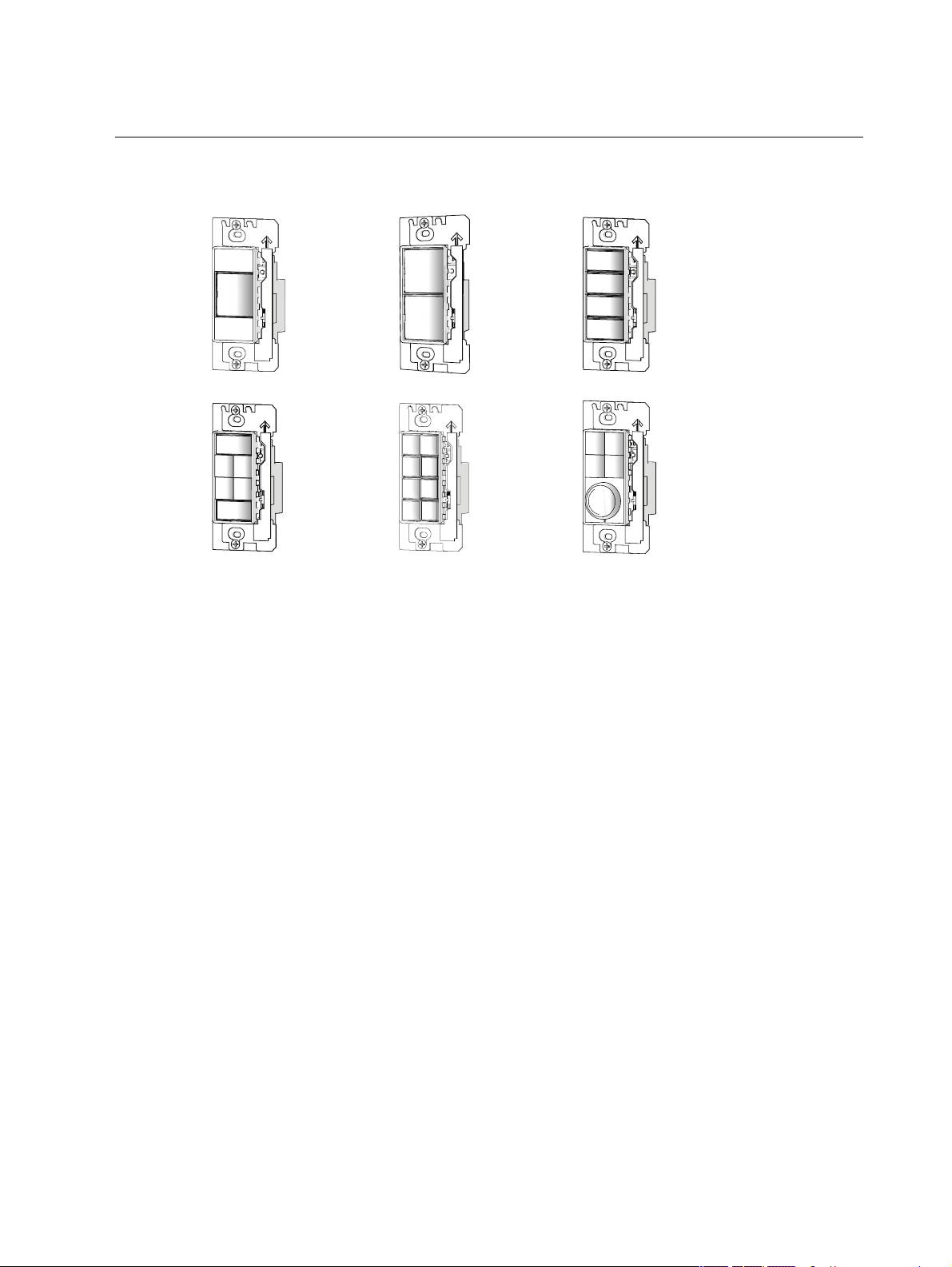
Station Functionality
•
•
•
•
•
•
This section provides detail for each stations function including its factory default settings, and
ea ch button default when the station function switch is set to Preset, Custom, and Zone.
1-Button Station on the next page
2-Button Station on page18
4-Button Station on page21
4-Button with Fader Station on page26
6-Button Station on page31
8-Button Station on page34
Station Func t ionality 14
Page 20

1-Button Station
•
•
•
•
The 1-button Elaho Inspire Station offers control of a single preset or zone as
determined by the Function switch setting.
Factory Defaults
The 1-button Inspire Station ships from the factory in the following default settings:
Rotary switche s are set to Addre ss 1, Space 1. Reference
Assignments on page40
All DIP switches are set to Off. Refe rence
With the Function switch set to P reset, Prese t 1 is the default.
With the Function switch set to Z one , Zone 1 is the default.
.
DIP Switch Settings on page40
Rotary Switch
.
Preset
The 1-button station supports the following button actions:
Push
Note: When DIP switch 1 is On and the station Function switch is set to Preset,
Se quence toggle mode is enabled (available on the 1-button sta tion only). This fe ature
allows the button to toggle the seque nce associated in the configured space. Reference
DIP Switch Settings on page40 for more information about DIP switches.
Hold
Double-tap
Double-tap the button to toggle the pre se t using a 1/2 second fade time.
15 Elaho Inspir e Station Pr og ramming G uid e
Page 21

Zone
The 1-button station supports the following button actions:
Push
Hold
Double-tap
Double-tap the button to toggle the zone to its full or off, using a 1/2 second fa de time.
Station Func t ionality 16
Page 22

Custom
The 1-button station provides the following button actions by default before configuration using
ElahoAccess:
Push
Hold
Double-tap
Double-tap the button to toggle the zone to its full or off, using a 1/2 second fa de time.
Note: These are the default button actions for the station when the Function switch is
set to Custom. For custom configuration using Ela hoAccess, reference the Ela hoAccess
Mobile App integrated help system.
17 Elaho Inspir e Station Pr og ramming G uid e
Page 23

2-Button Station
•
•
•
•
The 2-button Inspire Station offers control of two pre sets or 1 zone as determined by
the Function and DIP switch settings.
Factory Defaults
The 2-button Inspire Station ships from the factory in the following default settings:
Rotary switche s are set to Addre ss 1, Space 1. Reference
Assignments on page40
DIP switch 1 is set to On, for “Use Off” functionality. All others are set to Off.
Refere nce
With the Function switch set to P reset, Prese t 1 is the default starting preset.
With the Function switch set to Z one , Zone 1 is the default starting zone.
DIP Switch Settings on page40
.
.
Rotary Switch
Preset
The 2-button station supports the following button actions:
Push
Hold
Double-tap
Double-tap the button to toggle the pre se t using a 1/2 second fade time.
Note: DIP switch 1 is set to On by factory default, which reserve s button 2 on the
station for Off functionality. Reference DIP Switch Settings on page40 for instructions
to change this default setting.
Station Func t ionality 18
Page 24

Zone
The 2-button station supports the following button actions:
Push
Hold
Double-tap
Double-tap the button to toggle the zone to its extents using a 1/2 second fade time.
Custom
The 2-button station provides the following button actions by default before configuration using
ElahoAccess:
Push
Hold
19 Elaho Inspir e Station Pr og ramming G uid e
Page 25

Double-tap
Double-tap the button to toggle the zone to its extents using a 1/2 second fade time.
Note: These are the default button actions for the station when the Function switch is
set to Custom. For custom configuration using Ela hoAccess, reference the Ela hoAccess
Mobile App integrated help system.
Station Func t ionality 20
Page 26

4-Button Station
•
•
•
•
The 4-button Inspire Station offers control of four presets or two zone s, or space
combine actions for up to five consecutive spaces as de termined by the Function
and DIP switch settings.
Factory Defaults
The 4-button Inspire Station ships from the factory in the following default settings:
Rotary switche s are set to Addre ss 1, Space 1. Reference
Assignments on page40
.
Rotary Switch
DIP switch 1 is set to On, for “Use Off” functionality. All others are set to Off. Refere nce
DIP Switch Settings on page40
.
With the Function switch set to P reset, Prese t 1 is the default starting preset.
With the Function switch set to Z one , Zone one 1 is the default starting zone.
Preset
The 4-button station supports the following button actions:
Push
Hold
Double-tap
Double-tap the button to toggle the pre se t using a 1/2 second fade time.
21 Elaho Inspir e Station Pr og ramming G uid e
Page 27

Zone
The 4-button station supports the following button actions:
Push
Hold
Double-tap
Double-tap the button to toggle the zone to its extents using a 1/2 second fade time.
With No Zone Selected
When no zone is se lected, the raise selection and lower selection buttons (1 and 4) change the
intensity levels for the configured space.
A double-tap on the raise se lection or lower selection buttons (1 and 4) changes the le vels for
the configured spsace to their extents, using a 1/2 second fade time.
Station Func t ionality 22
Page 28

Custom
The 4-button station supports the following button actions by default before configuration using
ElahoAccess:
Push
Hold
Double-tap
Double-tap the button to toggle the zone to its extents using a 1/2 second fade time.
Note: These are the default button actions for the 4-button station when the Function
switch is set to Custom. For custom configuration using ElahoAccess, reference the
ElahoAccess Mobile App integrated help system.
Space Combine in Preset
Se tting the Function switch to Preset, with DIP switch 3 On, e nables space combine mode on the
4 button station. The 4-button station in Space Combine mode supports the following button
actions:
Push
23 Elaho Inspir e Station Pr og ramming G uid e
Page 29

Hold
Note: Double-tap is not a supported fea ture in Space Combine mode.
When the 4-button station in Space Combine mode , and the Function switch is set to Preset, the
spaces will wrap, meaning the last button on the station will combine with the first space
configured for control on the station. All combine actions are toggles (esse ntially wall toggles),
that both combine a nd un-combine the specified spaces.
Space Combine in Zone
Se tting the Function switch to Zone, with DIP switch 3 On, e nables Space Combine mode on the
4-button station. The 4 button station in Spa ce Combine mode supports the following button
actions:
Push
Hold
Note: Double-tap is not a supported fea ture in Space Combine mode.
Station Func t ionality 24
Page 30

Space Combine in Custom
Se tting the Function switch to Custom, with DIP switch 3 On, enables Space Combine mode on
the 4-button station. The 4 button station in Space Combine mode supports the following button
actions by default before configuration using E lahoAccess:
Push
Hold
Note: Double-tap is not a supported fea ture in Space Combine mode.
Note: These are the default button actions for the 4-button station when the Function
switch is set to Custom. For custom configuration using ElahoAccess, reference the
ElahoAccess Mobile App integrated help system.
25 Elaho Inspir e Station Pr og ramming G uid e
Page 31

4-Button with Fader Station
•
•
•
•
The 4-button with fader Inspire Station offers control of up to five presets or four
zones as determined by the Function and DIP switch settings.
Factory Defaults
The 4-button with fader Inspire Station ships from the factory in the following
default settings:
Rotary switche s are set to Addre ss 1, Space 1. Reference
Assignments on page40
DIP switch 1 is set to On for “Use Off” functionality. All others are set to Off. Refe rence
DIP Switch Settings on page40
With the Function switch set to P reset, the fader k nob is Preset 1.
With the Function switch set to Z one , Zone 1 is the starting zone .
.
.
Rotary Switch
Preset
The 4-button with fader station supports the following button actions:
Push
Note: Hold is not a supported feature in Preset mode.
Double-tap
Double-tap the button to toggle the pre se t using a 1/2 second fade time.
Note: When DIP switch 1 is set to On, the 4-button with fader station uses the fader
knob (push a ction) for Off functionality.
*Push the fader knob to execute an Off command anytime presets or zones are On in
the same space, otherwise the action toggles Preset 1. Reference DIP Switch S ettings
on page 40 for instructions to change this de fault setting.
Station Func t ionality 26
Page 32

Zone
The 4-button with fader station supports the following button and fa der actions:
Push
Hold
Double-tap
Double-tap the button or fader knob to toggle the zone or space using a 1/2 second fade time.
*Push the fader knob to execute an Off command anytime presets or zones are On in the same
space, otherwise the action toggles the space .
With No Zone Selected
When no zone is se lected, rota te the fader knob to perform a spa ce raise lower, changing all
zone levels for the configured space.
Double-tap on the fader knob to change the zone levels for the configured space to their
extents, using a 1/2 second fade time.
27 Elaho Inspir e Station Pr og ramming G uid e
Page 33

Zone with Color Control Enabled
With the Function switch set to Z one , and with Color Control mode enable d by configuring DIP
switches 5 and 6, the 4-button with fader station supports the following fader actions:
HSI Color Mode
Intensity
Saturation
Hue
Color Temp Mode
Intensity
Station Func t ionality 28
Page 34

Color Temp
Studio M ode
Intensity
Color Temp
Tint
With No Zone Selected
When no zone is se lected, rota te the fader knob to perform space wide commands, changing all
zone levels for the configured space.
29 Elaho Inspir e Station Pr og ramming G uid e
Page 35

Custom
The 4-button with fader station supports the following button and fa der actions by default before
configuration using ElahoAccess:
Push
Hold
Double-tap
Double-tap the button or fader knob to toggle the zone or space using a 1/2 second fade time.
*Push the fader knob to execute an Off command anytime presets or zones are On in the same
space, otherwise the action toggles the space .
Note: These are the default button and fader actions for Custom control mode. For
custom configuration using Ela hoAccess, reference the Ela hoAccess Mobile App
integrated help system.
Station Func t ionality 30
Page 36

6-Button Station
•
•
•
•
The 6-button Inspire Station offers control of up to six presets or four zones as
determined by the Function and DIP switch settings.
Factory Defaults
The 6-button Inspire Station ships from the factory in the following default settings:
Rotary switche s are set to Addre ss 1, Space 1. Reference
Assignments on page40
DIP switch 1 is set to On for “Use Off” functionality. All others are set to Off.
Refere nce
With the Function switch set to P reset, Prese t 1 is the default starting preset.
With the Function switch set to Z one , Zone 1 is the default starting zone.
DIP Switch Settings on page40
.
.
Rotary Switch
Preset
The 6-button station supports the following button actions:
Push
Hold
Double-tap
Double-tap the button to toggle the pre se t using a 1/2 second fade time.
Note: When DIP switch 1 is set to On, button 6 is designated for Off functionality.
Refere nce DIP Switch Settings on page40 for instructions to change this default setting.
31 Elaho Inspir e Station Pr og ramming G uid e
Page 37

Zone
The 6-button station supports the following button actions:
Push
Hold
Double-tap
Double-tap the button to toggle the selected zone or space using a 1/ 2 second fade time.
With No Zone Selected
When no zone is se lected, the raise and lower buttons (1 and 6) perform a space raise and spa ce
lower, changing a ll zone levels for the configured space.
A double-tap on the raise or lower button changes the zone leve ls for the configured space to
their extents, using a 1/2 second fade time.
Station Func t ionality 32
Page 38

Custom
The 6-button station supports the following button actions by default before configuration using
ElahoAccess:
Push
Hold
Double-tap
Double-tap the button to toggle the selected zone or space using a 1/ 2 second fade time.
Note: These are the default button actions for the station when the Function switch is
set to Custom. For custom configuration using Ela hoAccess, reference the Ela hoAccess
Mobile App integrated help system.
33 Elaho Inspir e Station Pr og ramming G uid e
Page 39

8-Button Station
•
•
•
•
The 8-button Inspire Station offers control of up to eight presets or four zones as
determined by the Function and DIP switch settings.
Factory Defaults
The 8-button Inspire station ships from the factory in the following default settings:
Rotary switche s are set to Addre ss 1, Space 1. Reference
Assignments on page40
All DIP switches are set to Off. Refe rence
With the Function switch set to P reset, Prese t 1 is the default starting preset.
With the Function switch set to Z one , Zone 1 raise is the default starting zone .
.
DIP Switch Settings on page40
Rotary Switch
Preset
The 8-button station supports the following button actions:
Push
Hold
.
Double-tap
Double-tap the button to toggle the pre se t using a 1/2 second fade time.
Note: When DIP switch 1 is set to On, the 8-button station uses button 8 for Off
functionality. Reference DIP Switch Settings on page40 for instructions to change this
default setting.
Station Func t ionality 34
Page 40

Zone
The 8-button station supports the following button actions:
Push
Hold
Double-tap
Double-tap the button to toggle the selected zone or space using a 1/ 2 second fade time.
With No Zone Selected
When no zone is se lected, the raise and lower buttons (7 & 8) perform a space raise and space
lower, changing a ll zone levels for the configured space.
A double-tap on the raise or lower button changes the zone leve ls for the configured space to
their extents, using a 1/2 second fade time.
35 Elaho Inspir e Station Pr og ramming G uid e
Page 41

Custom
The 8-button station supports the following button actions by default before configuration using
ElahoAccess:
Push
Hold
Double-tap
Double-tap the button to toggle the selected zone or space using a 1/ 2 second fade time.
Note: These are the default button actions for the station when the Function switch is
set to Custom. For custom configuration using Ela hoAccess, reference the Ela hoAccess
Mobile App integrated help system.
Station Func t ionality 36
Page 42

Station Miscellaneous
•
•
•
•
This section provides information pertaining to the mechanical features of the Inspire Stations
including the following:
Remove or Install the Wall Plate on the facing page
Install Button Legends on page 39
Rotary Switch Assignments on page40
DIP Switch Settings on page40
37 Elaho Inspir e Station Pr og ramming G uid e
Page 43

Remove or Install the Wall Plate
Remove Wall Plate
After station installation is complete, to gain further access to the
feature s and set station
The wall plate is secured to the station with magnets that a re attached to the wall plate.
1. Using your index finger and thumb, lift the left and right side edges of the bottom of the
wall plate, disenga ging the ma gnets. The magnets that secure the wall plate are strong.
You will need a good grip on the plate to lift it awa y.
2. When the bottom of the wall plate is free from the magnets, continue lifting until the top
of the pla te is free from the tabs on the top of the station e lectronics assembly.
Function switch
, you must first remove the sta tion wall plate .
Record/Program Mode
Install Wall Plate
1. Align the top of the wall plate to the station and angle the bottom
approximately 20 degrees.
2. Hook the top of the wall plate to the tabs loca ted on the station
electronics assembly. T o ensure the wall plate is hooked properly on the
top hook, wiggle it slightly side to side .
3. Swing the bottom of the wall plate down until the magnets engage.
4. If the wall plate does not fully attach automatically, wiggle the bottom
of the pla te until all of the magnets are seated properly to the station
and the plate is secure.
Note: When installing a multi-gang wall plate to a sta tion and the stations are not
aligned prope rly in the back box, the wall plate will not attach properly.
Loosen the screws that se cure the station to the back box, adjust each station to
improve the alignment, secure the screws, then retry wall plate installa tion.
Station Miscellaneo us 38
Page 44

Install Button Legends
•
•
Inspire Stations ship with standard button legends installe d beneath a cle ar lens. An additional
sheet of sta ndard button legends are provided for field installation as needed.
Note: Customize and print your own button legends on standard transparency.
Download the button legend template provided on the Echoflex website a t
echoflexsolutions.com.
Ea ch button can have a legend, installed beneath the button lens. To remove, install, or re place
a button legend you must first re move the beze l and button lens from the station electronics.
Ea ch button can have a legend, installed beneath the button lens. To remove, install, or re place
a button legend you must first re move the beze l and button lens from the station electronics.
1. Remove the be zel from the station electronics.
Ea ch corner of the bezel is provided with a notch to a ssist
with bezel removal. Use a nail to lift a corner free , then
gently remove the bezel from the station.
2. Remove the button lens.
Using the pads of your thumb,
press on the le ns and slide the
lens left, toward the hinge
points.
3. Once the le ns is removed,
remove the existing legend and
insert a custom legend.
4. Replace the lens onto the button by aligning the grooves of
the lens to the button, then sliding the lends in place
starting at the hinge. Slide the lens until it covers the entire
button and click s into place.
5. Replace the bezel to the station electronics when all
legends and lenses are in place.
39 Elaho Inspir e Station Pr og ramming G uid e
Page 45

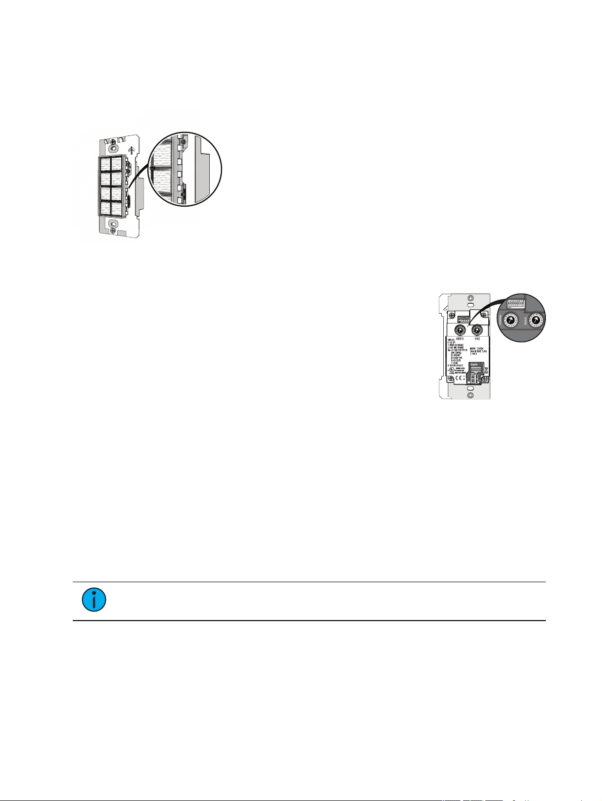
Rotary Switch Assignments
Two rotary switches on the rear pa nel of the station provide for
station address and space assignment. Each station must be se t to a
unique station a ddre ss for the assigned space.
By default, these switches are set to station Address 1, Space 1.
Events and commands are shared by all devices within an assigne d
space.
DIP Switch Settings
DIP switches on the rear panel of the station provide for designation of
“Off” functionality, the ability to disable amber button LEDs, 4 button
station spa ce combine controls, 4 button with fader station color
control mode settings, and the ability to restore the station to its
factory de faults.
Note: Echoflex recommends that you reset power to the station after changing a DIP
switch setting.
Switch
#
Use Off - P rovide s “Use O ff” functiona lity.
1
Function switch is set to P reset mode, enables sequence toggle.
Ambe r LED Disa ble - When this switch is set to On, amber button LEDs on the station will be
2
disabled. The default setting is Off. Ambe r LEDs are provided as the default so the station
glows in darkened spaces, allowing it to be easily located.
Space Combine Mode -
3
combine.
Fa de T ime O verride (Disable) - Applies a 0 second fade time to all station actions for non-dim
4
switched mode beha vior (when dimming features are not wanted)
5
Zone Color Control selection switch) of the station into Color Control mode. See .
6
7 Reserved for future deve lopment
Restore to Defaults a t boot. Setting this DIP switch "On", then cycling power to the station
8
restores the sta tion to fa ctory defaults. Set the DIP switch “Off” after the power has cycle d.
4-button station only
4-button with fader station only
Note: When the station Function switch is set to Custom, only DIP switch number 8
applies. All other DIP switch settings are ignored.
Use
1-button station only
, changes the station persona lity, enabling space
, changes the Zone mode (Function
, when set to On and the
DIP Switch Settings above
Station Miscellaneo us 40
Page 46

4-Button with Fader Station Color Mode DIP Switch Settings
DIP switches 5 and 6 on the 4-button with fader station set Color Mode functionality for the
fader knob when the station is also set to Zone control mode:
MODE DIP 5 DIP 6 Push action Rotate action
Intensity Off Off Se lection Toggle Se lection Raise / Lower
Color Temp O ff O n
HSI Color On Off
Studio On On
Toggle between Inte nsity
and Color Temp
Toggle between Inte nsity,
Sa tura tion, and Hue
Toggle between Inte nsity,
Color Temp, and Tint
Se lection Raise / Lower for
Intensity and Color Temp
Se lection Raise / Lower for
Intensity, Saturation, a nd Hue
Se lection Raise / Lower for
Intensity, Color Temp, and Tint
41 Elaho Inspir e Station Pr og ramming G uid e
Page 47

Station Miscellaneo us 42
Page 48

Main O ffi ce n Squam ish, BC, Canada n Toll Free +888 324 6359 n Phone + 778 733 0111 n Fax + 604 815 0078
Em a il info@echoflexs olutions . com n W e b echofle xs olutions .com n P roduct informa tion a nd specifica tions s ubje ct
to change. n ©2018 E choflex S olutions , Inc. n E choflex intends this docume nt to be provided in its entire ty.
8186M1220-3. 1. 0 n Revision A n Relea sed 2018-09
 Loading...