

Page 1
ETC® Installation Guide
Unison® Echo DRd Network Termination Kit
Overview
The Echo DRd Network Termination Kit is provided for field installation into a DRd enclosure for use
with the Echo Architectural Control Processor.
Kit incudes:
Qty Description Part Number
1 DRd Left I/O Card 7183B5705
5 Screw, 6-32 x .250 HW213
1 Cat5 Termination Kit 4101A2003
1 2 ft (0.61m) Cat5 Cable N4035
Tools Required
• No. 2 Phillips screwdriver
Procedure
WARNING:
Power must be turned OFF when you perform this procedure. Before service,
de-energize main feed to dimmer enclosure and follow appropriate Lockout/
Tagout procedures as described in NFPA Standard 70E.
It is important to note that electrical equipment such as dimmer enclosures can
present an arc flash safety hazard if improperly serviced. This is due to available
large short circuit currents on the feeders of the equipment. Any work on
energized equipment must comply with OSHA Electrical Safe Working
Practices.
Step 1: Turn off power to the DRd enclosure.
WARNING:
Failure to disconnect all power to the DRd before working in the enclosure
could result in serious injury or death.
Step 2: Loosen screws on the module retention rail on the left side of the DRd enclosure and slide
the rail to the left.
Step 3: If installed, remove the Architectural Control Processor, Station Power Module, and at
least three dimmer modules from the lower portion of the enclosure to provide work space
inside the enclosure.
Step 4: Use a digital voltmeter and verify that power is off by checking voltages for all
combinations between the phase bars, neutral, and ground (earth).
Corporate Headquarters
London, UK
Rome, IT
Holzkirchen, DE
Hong Kong Rm 1801, 18/F, Tower 1 Phase 1, Enterprise Square, 9 Sheung Yuet Road, Kowloon Bay, Kowloon, Hong Kong Tel +852 2799 1220 Fax +852 2799 9325
Service:
Web:
7186M2110
Echo Network Termination Kit Page 1 of 2 Electronic Theatre Controls, Inc.
Unit 26-28, Victoria Industrial Estate, Victoria Road, London W3 6UU, UK Tel +44 (0)20 8896 1000 Fax +44 (0)20 8896 2000
Via Pieve Torina, 48, 00156 Rome, Italy Tel +39 (06) 32 111 683 Fax +44 (0) 20 8752 8486
(Americas) service@etcconnect.com
www.etcconnect.com
Rev A Released 2014-05
3031 Pleasant View Road, P.O. Box 620979, Middleton, Wisconsin 53562-0979 USA Tel +608 831 4116 Fax +608 836 1736
Ohmstrasse 3, 83607 Holzkirchen, Germany Tel +49 (80 24) 47 00-0 Fax +49 (80 24) 47 00-3 00
Copyright © 2014 ETC. All Rights Reserved. Product information and specifications subject to change.
(UK) service@etceurope.com (DE) techserv-hoki@etcconnect.com
ETC intends this document to be provided in its entirety.
(Asia) service@etcasia.com
Page 2
ETC Installation Guide
Echo Network Termination Kit
Step 5: If the Category 5 cable running to the enclosure does not have a female RJ45 connector,
reference the included Ethernet Cat5 Termination Kit Setup Guide to terminate
Category 5 wiring to the provided Cat5 mounting box and connector.
• When installing, attach the Cat5 mounting box at the back of the enclosure, left of
the neutral lug and at least one inch from any exposed copper.
WARNING:
Failure to properly space the mounting box from the exposed power lugs could
result in damage to the DRd and its components and poses a serious safety
risk.
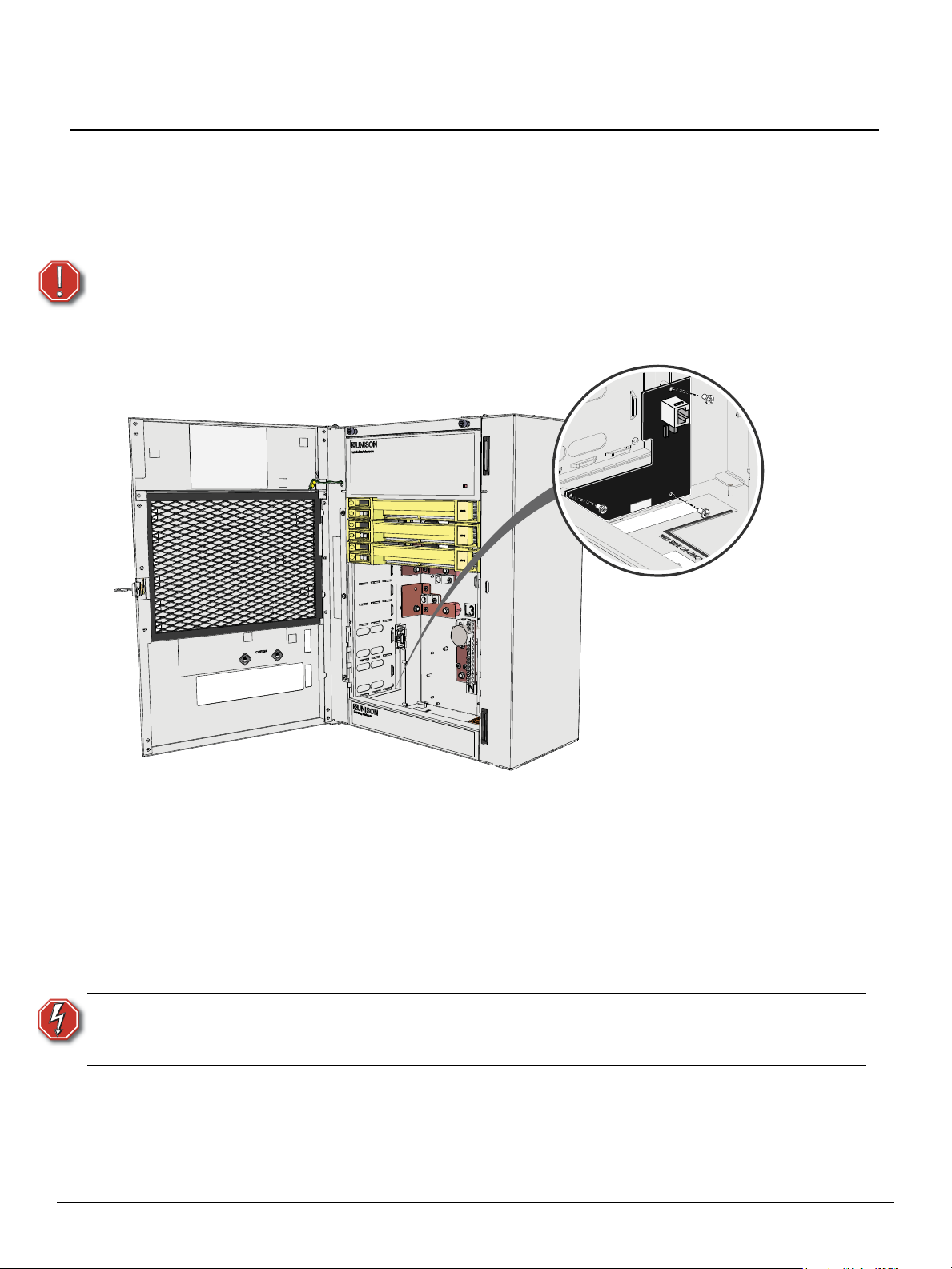
Install the I/O card
Step 1: Align the network termination card to the mounting studs at the lower left of the enclosure.
Step 2: Use four of the included screws to secure the card to the enclosure.
Step 3: Connect the included Ethernet patch cable from the previously installed Cat5 termination
box to the receptacle on the network termination card.
Step 4: Tie back and secure the Ethernet patch cable neatly inside the enclosure to ensure it does
not interfere with module installation and DRd operation.
Step 5: Replace the dimmer modules, Station Power Module and Architectural Control Processor
into the slots they were previously removed.
Step 6: Slide the module retention bar to the right and tighten the screws to secure it in place.
WARNING:
Step 7: Supply power to the DRd enclosure.
Step 8: Unless structural changes are being made to the existing system, no dimming or
Echo Network Termination Kit Page 2 of 2 Electronic Theatre Controls, Inc.
Never power up or operate the Unison DRd enclosure without all modules
installed. Failure to comply exposes you to dangerously high voltages that may
result in death by electrical shock.
architectural re-configuration should be necessary. If the system is being modified,
reference the related Architectural Control Processor Configuration and Programming
Guide for configuration setup and operation information.
 Loading...