

Page 1
ETC Installation Guide
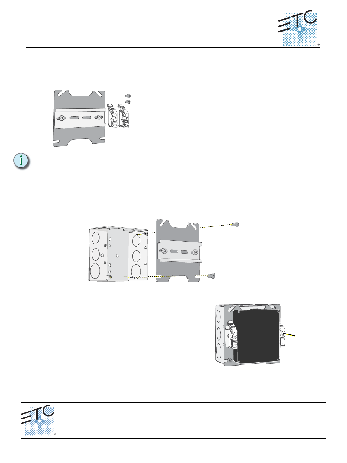
Low Voltage DIN rail Cover Kit includes:
• One 4” cover plate with DIN rail
• Two 8-32x3/8” screws
• Two Z-terminal DIN rail end stops
* Back box
provided
by others.
Step 3: Install the DIN rail mounted device (sold
separately) to the rail and wire it according to the
instructions provided in the related product
installation instructions.
Step 4: Two Z-terminal DIN rail end stops are provided to
secure the DIN rail mounted device to the rail.
a: Attach an end stop to the rail on each side of
the device.
b: Secure each end stop in place using the built-
in set screw.
set
screw
Echo Low Voltage DIN rail Cover Kit
Overview
The Unison Echo® Low Voltage DIN rail Cover Kit provides surface mount installation of compatible DIN rail
mounted Echo devices (sold separately) to a standard 4” (10.16 cm) flush or surface mounted electrical
back box. The back box is provided by others.
Note:
Installation
Step 1: Align the cover plate to the installed back box. The cover can be installed universally for a
Step 2: Secure the cover plate in place using the two 8-32x 3/8” screws provided in the kit. Screws
All low voltage Class II control cables must be run in separate conduit from Class 1 power
wires.
Installation should follow all local codes and standard wiring practices.
vertical or horizontal mounting.
should be installed in opposite corners.
Corporate Headquarters Middleton, WI, USA Tel +608 831 4116 Service: (Americas) service@etcconnect.com
Low Voltage DIN rail Cover Kit Page 1 of 1 Electronic Theatre Controls, Inc.
London, UK
Rome, IT
Holzkirchen, DE
Hong Kong
Web: www.etcconnect.com
7186M2142
Tel +44 (0)20 8896 1000 Service: (UK) service@etceurope.com
Tel +39 (06) 32 111 683 Service: (UK) service@etceurope.com
Tel +49 (80 24) 47 00-0 Service: (DE) techserv-hoki@etcconnect.com
Tel +852 2799 1220 Service: (Asia) service@etcasia.com
Rev A Released 2016-02 ETC intends this document to be provided in its entirety.
© 2016 ETC. All Rights Reserved. Product information and specifications subject to change.
 Loading...