

Page 1
ETC® Installation Guide
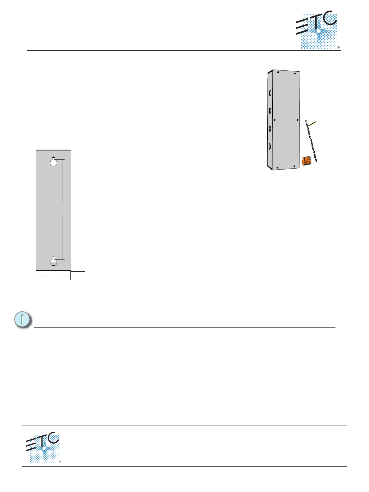
6’ (1.8m)
included
11. 5”
292mm
4”
102mm
14”
356mm
3.15” deep
(80mm)
Mount Box to Wall
This box is provided with four knockouts on each long side, sharing the same
conduit entry locations as the wall mount Echo Station Power Supply. All wiring
terminations are accessible from the front with the cover removed. If you are
mounting this box directly next to the wall mount Echo Station Power Supply, use
appropriate attaching hardware and wire protection hardware (not provided).
Step 1: Remove the six screws securing the front cover to the box.
Step 2: Align the unit to the wall and mark the mounting keyholes.
Alternatively, reference the dimensioned drawing on the left.
Step 3: Drill the mounting holes and install the mounting hardware (not
provided). Expose at least 3/4” (19mm) of threads for mounting the
unit.
Step 4: Attach the termination box to the mounting hardware, where the
back side of the unit is flush to the wall, then tighten the mounting
hardware.
Unison® EchoConnect Cat5 Termination Box
Overview
This EchoConnect Cat5 termination box is intended for installation on a wall
or flat vertical surface, typically near or directly next to a wall mount Echo
Station Power Supply.
Use the Unison EchoConnect Cat5 termination box to facilitate termination
of up to 16 runs of Category 5 (or equivalent) cable on the EchoConnect
communication bus.
The following supplies are included for installation convenience:
• 6 feet (1.8m) of Belden 8471 cable
• Six position screw terminal connector J3263-F (x1)
Rough-In Conduit and Wiring
Note:
Terminations include:
• EchoConnect (Belden 8471 twisted pair) installed between this Termination Box and the adjacent
Echo Station Power Supply. This wire pair is provided.
• Category 5 (or equivalent) cable installed between this Termination Box and each Echo Station
control run. Up to 16 runs of EchoConnect are supported.
• ESD ground wires are required between this Termination Box ground termination bar and any
Echo station that is not installed entirely in grounded metal conduit.
EchoConnect Cat5 Termination Box Page 1 of 2 Electronic Theatre Controls, Inc.
Corporate Headquarters
London, UK
Rome, IT
Holzkirchen, DE
Hong Kong Rm 1801, 18/F, Tower 1 Phase 1, Enterprise Square, 9 Sheung Yuet Road, Kowloon Bay, Kowloon, Hong Kong Tel +852 2799 1220 Fax +852 2799 9325
Service:
(Americas) service@etcconnect.com
Web:
www.etcconnect.com
7186M2130
Follow all local codes and restrictions.
3031 Pleasant View Road, P.O. Box 620979, Middleton, Wisconsin 53562-0979 USA Tel +608 831 4116 Fax +608 836 1736
Unit 26-28, Victoria Industrial Estate, Victoria Road, London W3 6UU, UK Tel +44 (0)20 8896 1000 Fax +44 (0)20 8896 2000
Via Pieve Torina, 48, 00156 Rome, Italy Tel +39 (06) 32 111 683 Fax +44 (0) 20 8752 8486
Ohmstrasse 3, 83607 Holzkirchen, Germany Tel +49 (80 24) 47 00-0 Fax +49 (80 24) 47 00-3 00
Rev A Released 2014-05
Copyright © 2014 ETC. All Rights Reserved. Product information and specifications subject to change.
(UK) service@etceurope.com (DE) techserv-hoki@etcconnect.com
ETC intends this document to be provided in its entirety.
(Asia) service@etcasia.com
Page 2
ETC Installation Guide
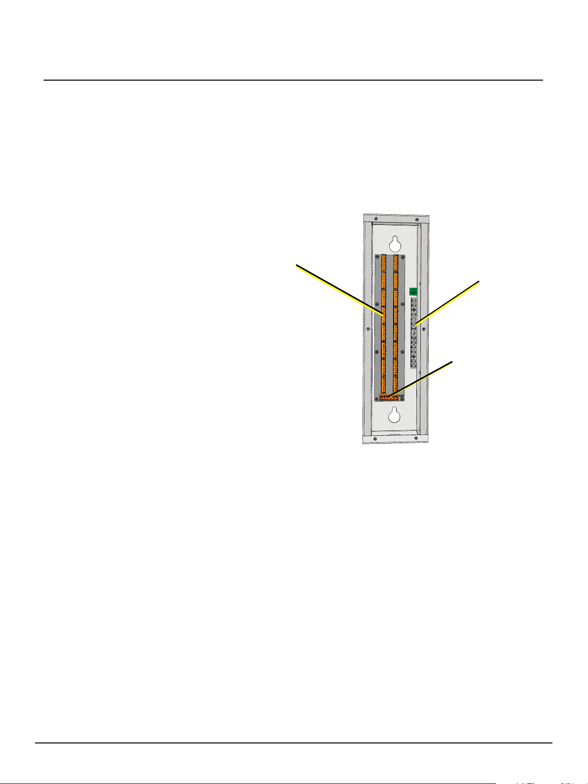
(16) Cat5
Inputs
ESD
ground bar
EchoConnect to
Echo Station
Power Supply
Terminate Wiring
Connect Cat5 Inputs
Stations that are installed for use with Cat5 control wire for the EchoConnect station bus are supplied
with a Cat5 Station Termination Kit (ETC part number 7186A1207). This termination kit includes all of
the parts and instructions that are required to complete EchoConnect station terminations when using
Cat5 cable.
The last station in the control run does not require use of the second 8 position IDC connector
(ETC part number J3409-F) provided in the Cat5 Station Termination Kit.
Use the second connector to
terminate the station data run to this
termination box. Refer to the Cat5
Cable Preparation for IDC
Termination Setup Guide
(4100M2202 revision D or later),
included with the Station
Termination Kit for cable
preparation and termination
instructions.
Terminate Cat5 Wiring
Step 1: Connect the
prepared Cat5 cable
to any of the 16
available Cat5
receptacles in the
termination box.
Step 2: Repeat for each
EchoConnect station
data run in the
system.
Connect EchoConnect to the Echo Station Power Supply
Step 1: Run the EchoConnect cable (supplied Belden 8471 twisted pair) between this termination
box and the adjacent Echo Station Power Supply.
Step 2: Remove the six position screw connector from the bottom position of the termination box.
Step 3: Strip 3/8” (9-10mm) from each wire end in the supplied Belden 8471.
Step 4: Maintain the wire twist as close to the connection as possible, then insert the white wire
into the data + terminal (1) and the black wire into the data - terminal (2) and tighten the
screws firmly onto each wire.
Step 5: Replace the connector to the board.
Step 6: Remove the two position screw connector from the Echo Station Power Supply
termination board.
Step 7: Maintain the wire twist as close to the connection as possible, then insert the white wire
into the data + terminal (1) and the black wire into the data - terminal (2) and tighten the
screws firmly onto each wire.
Step 8: Replace the connector to the board.
Final Installation
Replace the cover to the termination box and secure it in place using the six screws previously
removed. Reference the related station power supply installation documentation for power up and test
procedures.
EchoConnect Cat5 Termination Box Page 2 of 2 Electronic Theatre Controls, Inc.
 Loading...