

Page 1

Architectural Control Processor
Configuration Manual
1.0
Copyright © Electronic Theatre Controls, Inc.
All Rights reserved.
Product information and specifications subject to change.
Part Number:
7186M1200-1.0.0
Released: 2014-08
Rev A
Page 2

ETC®, Unison®, and Echo™, are either registered trademarks or trademarks of Electronic Theatre Controls, Inc.
in the United States and other countries.
All other trademarks, both marked and not marked, are the property of their respective owners.
ETC intends this document, whether printed or electronic, to be provided in its entirety.
Page 3

Table of Contents
Introduction . . . . . . . . . . . . . . . . . . . . . . . . . . 1
Warnings and Notice Conventions . . . . . . . . . . . . . . . . . . . . . . .2
Contacting ETC . . . . . . . . . . . . . . . . . . . . . . . . . . . . . . . . . . . . . .3
Overview . . . . . . . . . . . . . . . . . . . . . . . . . . . . . . . . . . . . . . . . . . . . . .4
Concepts and Definitions. . . . . . . . . . . . . . . . . . . . . . . . . . . . . . .4
Installation Environment Requirements . . . . . . . . . . . . . . . . . . . . . . .8
Chapter 1
Chapter 2
UI Overview and Installation . . . . . . . . . . . . 10
User Interface Overview. . . . . . . . . . . . . . . . . . . . . . . . . . . . . . . . . .11
LCD Display. . . . . . . . . . . . . . . . . . . . . . . . . . . . . . . . . . . . . . . .11
Wake . . . . . . . . . . . . . . . . . . . . . . . . . . . . . . . . . . . . . . . . . . . . .11
Touch Wheel . . . . . . . . . . . . . . . . . . . . . . . . . . . . . . . . . . . . . . .11
Enter . . . . . . . . . . . . . . . . . . . . . . . . . . . . . . . . . . . . . . . . . . . . .12
Back. . . . . . . . . . . . . . . . . . . . . . . . . . . . . . . . . . . . . . . . . . . . . .12
Control Menu Shortcut. . . . . . . . . . . . . . . . . . . . . . . . . . . . . . . .12
Numeric Button Pad. . . . . . . . . . . . . . . . . . . . . . . . . . . . . . . . . .12
Removable Media . . . . . . . . . . . . . . . . . . . . . . . . . . . . . . . . . . .14
Reset Switch . . . . . . . . . . . . . . . . . . . . . . . . . . . . . . . . . . . . . . .14
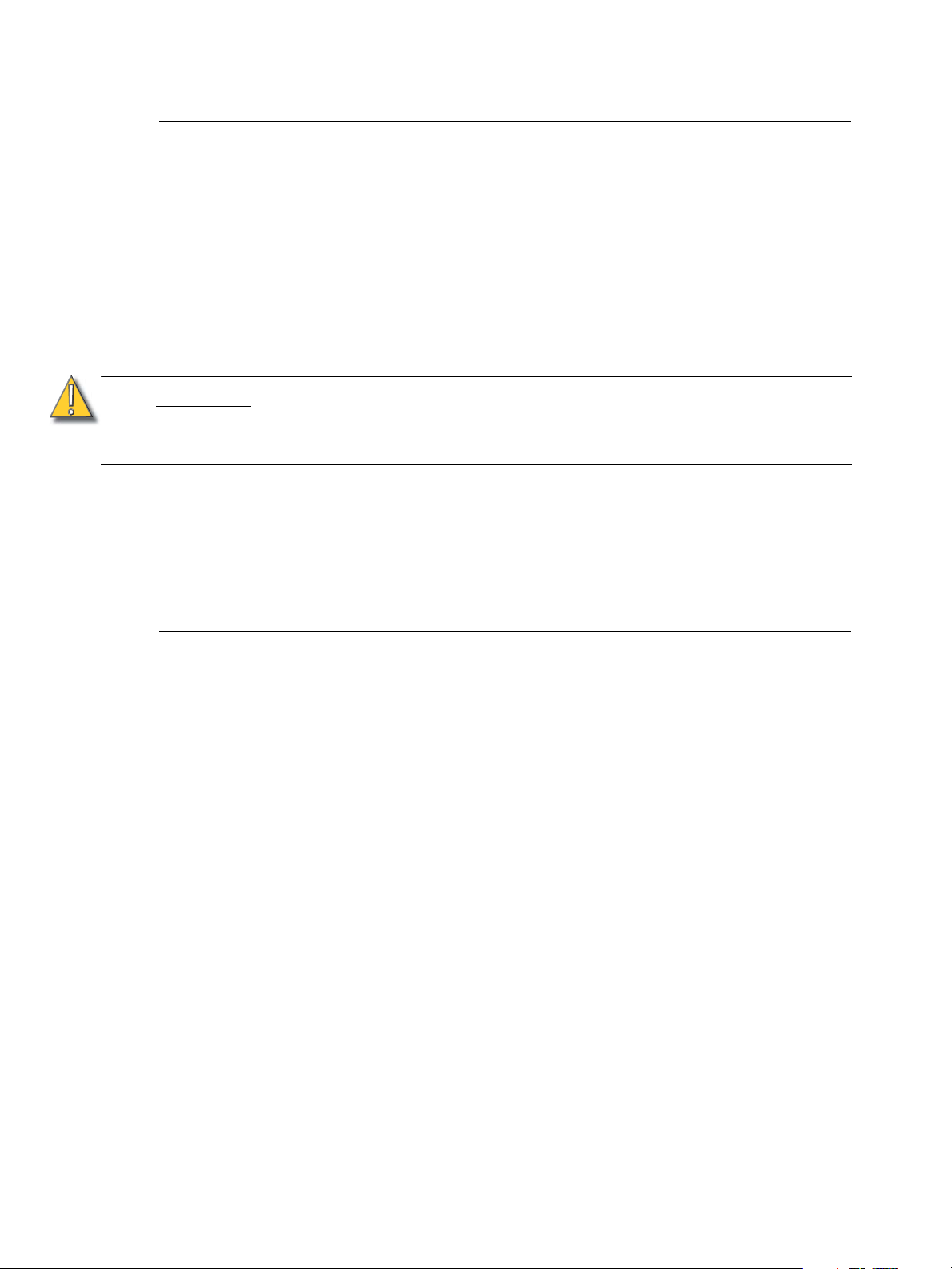
Install the Echo ACP . . . . . . . . . . . . . . . . . . . . . . . . . . . . . . . . . . . .15
System Status . . . . . . . . . . . . . . . . . . . . . . . . . . . . . . . . . . . . . .16
Echo ACP Basic Navigation . . . . . . . . . . . . 18
Status Display . . . . . . . . . . . . . . . . . . . . . . . . . . . . . . . . . . . . . . . . .19
DRd Dimming Rack Status Display . . . . . . . . . . . . . . . . . . . . . .19
Arch Control Status Display. . . . . . . . . . . . . . . . . . . . . . . . . . . .20
Status / Error Messages. . . . . . . . . . . . . . . . . . . . . . . . . . . . . . . . . .21
Status / Error Messages Generated by the Echo ACP . . . . . . .21
Status / Errors Messages Generated by the DRd Dimming Engine
22
Menu Navigation . . . . . . . . . . . . . . . . . . . . . . . . . . . . . . . . . . . . . . .23
Chapter 3
Echo ACP Configuration Manual i
Programming . . . . . . . . . . . . . . . . . . . . . . . 24
About Menu . . . . . . . . . . . . . . . . . . . . . . . . . . . . . . . . . . . . . . . . . . .25
About Dimmer . . . . . . . . . . . . . . . . . . . . . . . . . . . . . . . . . . . . . .25
Levels Summary . . . . . . . . . . . . . . . . . . . . . . . . . . . . . . . . . . . .25
Version Info . . . . . . . . . . . . . . . . . . . . . . . . . . . . . . . . . . . . . . . .26
Space Combine . . . . . . . . . . . . . . . . . . . . . . . . . . . . . . . . . . . . .26
Dimming Setup Menu. . . . . . . . . . . . . . . . . . . . . . . . . . . . . . . . . . . .27
Dimmer Setup . . . . . . . . . . . . . . . . . . . . . . . . . . . . . . . . . . . . . .27
Patch DMX Input . . . . . . . . . . . . . . . . . . . . . . . . . . . . . . . . . . . .29
Patch sACN Input . . . . . . . . . . . . . . . . . . . . . . . . . . . . . . . . . . .30
Page 4

Emergency Setup . . . . . . . . . . . . . . . . . . . . . . . . . . . . . . . . . . .31
Quick Rack Setup . . . . . . . . . . . . . . . . . . . . . . . . . . . . . . . . . . .34
Arch Setup Menu . . . . . . . . . . . . . . . . . . . . . . . . . . . . . . . . . . . . . . .37
Remote Record . . . . . . . . . . . . . . . . . . . . . . . . . . . . . . . . . . . . .37
Data Source Settings. . . . . . . . . . . . . . . . . . . . . . . . . . . . . . . . .37
Data Loss & Power On . . . . . . . . . . . . . . . . . . . . . . . . . . . . . . .38
Preferences . . . . . . . . . . . . . . . . . . . . . . . . . . . . . . . . . . . . . . . .39
Space Setup . . . . . . . . . . . . . . . . . . . . . . . . . . . . . . . . . . . . . . .40
Network Settings . . . . . . . . . . . . . . . . . . . . . . . . . . . . . . . . . . . .41
Dimming Control Menu. . . . . . . . . . . . . . . . . . . . . . . . . . . . . . . . . . .43
Set Levels . . . . . . . . . . . . . . . . . . . . . . . . . . . . . . . . . . . . . . . . .43
Dimmer Check . . . . . . . . . . . . . . . . . . . . . . . . . . . . . . . . . . . . . .44
Release Set Levels . . . . . . . . . . . . . . . . . . . . . . . . . . . . . . . . . .44
Arch Control Menu . . . . . . . . . . . . . . . . . . . . . . . . . . . . . . . . . . . . . .45
Presets. . . . . . . . . . . . . . . . . . . . . . . . . . . . . . . . . . . . . . . . . . . .45
Sequences. . . . . . . . . . . . . . . . . . . . . . . . . . . . . . . . . . . . . . . . .46
File Operations Menu . . . . . . . . . . . . . . . . . . . . . . . . . . . . . . . . . . . .49
Save Rack Configurations . . . . . . . . . . . . . . . . . . . . . . . . . . . . .49
Save Dimming Configuration . . . . . . . . . . . . . . . . . . . . . . . . . . .50
Load Dimming Configuration . . . . . . . . . . . . . . . . . . . . . . . . . . .51
Save Arch Configuration . . . . . . . . . . . . . . . . . . . . . . . . . . . . . .52
Load Architectural Configuration . . . . . . . . . . . . . . . . . . . . . . . .53
Restore Defaults . . . . . . . . . . . . . . . . . . . . . . . . . . . . . . . . . . . .54
Update Firmware . . . . . . . . . . . . . . . . . . . . . . . . . . . . . . . . . . . .55
Chapter 4
Appendix A
View/Clear Errors Menu . . . . . . . . . . . . . . . . . . . . . . . . . . . . . . . . . .56
Restricted Access Menu. . . . . . . . . . . . . . . . . . . . . . . . . . . . . . . . . .57
Login . . . . . . . . . . . . . . . . . . . . . . . . . . . . . . . . . . . . . . . . . . . . .57
Change Passcode . . . . . . . . . . . . . . . . . . . . . . . . . . . . . . . . . . .58
Default Access. . . . . . . . . . . . . . . . . . . . . . . . . . . . . . . . . . . . . .58
Service . . . . . . . . . . . . . . . . . . . . . . . . . . . . 60
Service and Maintenance. . . . . . . . . . . . . . . . . . . . . . . . . . . . . . . . .61
Replace a Echo ACP . . . . . . . . . . . . . . . . . . . . . . . . . . . . . . . . .61
Hardware Reset Switch . . . . . . . . . . . . . . . . . . . . . . . . . . . . . . .61
Dimmer Specifications . . . . . . . . . . . . . . . . 62
Unison DRd Rack Compatible Modules . . . . . . . . . . . . . . . . . . . . . .62
Dimmer Module Defaults . . . . . . . . . . . . . . . . . . . . . . . . . . . . . . . . .65
Compatible Loads . . . . . . . . . . . . . . . . . . . . . . . . . . . . . . . . . . . . . .66
Dimmer Modes . . . . . . . . . . . . . . . . . . . . . . . . . . . . . . . . . . . . . . . . .68
Dimmer Properties . . . . . . . . . . . . . . . . . . . . . . . . . . . . . . . . . . . . . .71
Appendix B
ii Echo ACP Configuration Manual
Echo ACP Web Interface . . . . . . . . . . . . . . 74
Access the Web Interface . . . . . . . . . . . . . . . . . . . . . . . . . . . . . . . .74
Page 5

System. . . . . . . . . . . . . . . . . . . . . . . . . . . . . . . . . . . . . . . . . . . .74
Dimmers . . . . . . . . . . . . . . . . . . . . . . . . . . . . . . . . . . . . . . . . . .75
Set Levels . . . . . . . . . . . . . . . . . . . . . . . . . . . . . . . . . . . . . . . . .75
Presets. . . . . . . . . . . . . . . . . . . . . . . . . . . . . . . . . . . . . . . . . . . .75
Sequences. . . . . . . . . . . . . . . . . . . . . . . . . . . . . . . . . . . . . . . . .76
Files . . . . . . . . . . . . . . . . . . . . . . . . . . . . . . . . . . . . . . . . . . . . . .76
Appendix C
Echo ACP Menu Flow Chart. . . . . . . . . . . . 78
Menu Flow Chart . . . . . . . . . . . . . . . . . . . . . . . . . . . . . . . . . . . . . . .79
<ChapterNumber> iii
Page 6
Introduction
Welcome to the Echo Architectural Control Processor (E-ACP) Configuration Manual. This
manual contains information for user configuration and programming of the Echo ACP.
The Echo ACP installs into a Unison DRd enclosure and provides centralized access to the
dimming, switching, rack enclosure settings, DMX setup, and interface to Echo controls
stations over the EchoConnect control network.
The Echo ACP serves as the real time processor for incoming control signals from other
Echo processors, control stations, and control sources including DMX (input) and sACN (up
to four sACN universes), and transmits that information to the individual dimmers, relays
and control stations.
An optional Echo Station Power Module (E-SPM) fits in the module slot directly above the
Echo ACP and provides power for up to 16 Echo control stations on the topology-free
EchoConnect control network. Reference the related Echo Station Power Module Install
Guide for details.
1 Echo ACP Configuration Manual
Page 7
Warnings and Notice Conventions
These symbols are used throughout this manual to alert you to danger or important
information:
Note:
CAUTION:
WARNING:
WARNING:
Notes are helpful hints and information that are supplemental to the main text.
A Caution statement indicates situations where there may be undefined or
unwanted consequences of an action, potential for data loss, or an equipment
problem.
A Warning statement indicates situations where damage may occur, people
may be harmed, or there are serious or dangerous consequences of an
action.
RISK OF ELECTRIC SHOCK! This warning statement indicates situations
where there is a risk of electric shock.
Introduction 2
Page 8

Contacting ETC
For questions about delivery of your Echo system, contact ETC Systems Group. For
general information, your most convenient resources are the references provided in this
manual. To search more widely try the ETC web site at www.etcconnect.com.
For technical questions about Echo systems, contact ETC Technical Services directly at
one of the offices listed below. Emergency service is available from all ETC offices outside
of normal business hours. When calling for assistance, please be near the equipment for
troubleshooting and have the following information handy:
• Your location and job name.
• A complete list of ETC equipment.
• A complete list of other installed products and components connected to the system
you are troubleshooting.
• DMX control source, if any.
Americas
ETC International
Technical Services Department
3031 Pleasant View Road
Middleton, WI 53562
800-775-4382 (USA, toll-free)
+1-608 831-4116
service@etcconnect.com
Asia
ETC Asia, Ltd.
Technical Services Department
Room 1801, 18/F, Tower 1, Phase 1
Enterprise Square
9 Sheung Yuet Road
Kowloon Bay, Kowloon, Hong Kong
+852 2799 1220
service@etcasia.com
United Kingdom
Electronic Theatre Controls, Ltd.
Technical Services Department
26 - 28 Victoria Industrial Estate
Victoria Road,
London W3 6UU, UK
+44 (0)20 8896 1000
service@etceurope.com
Germany
Electronic Theatre Controls, GmbH
Technical Services Department
Ohmstrasse 3
93607, Holzkirchen, Germany
+49 (80 24) 47 00-0
techserv-hoki@etcconnect.com
Please email comments about this manual to: TechComm@etcconnect.com
3 Echo ACP Configuration Manual
Page 9
Overview
Concepts and Definitions
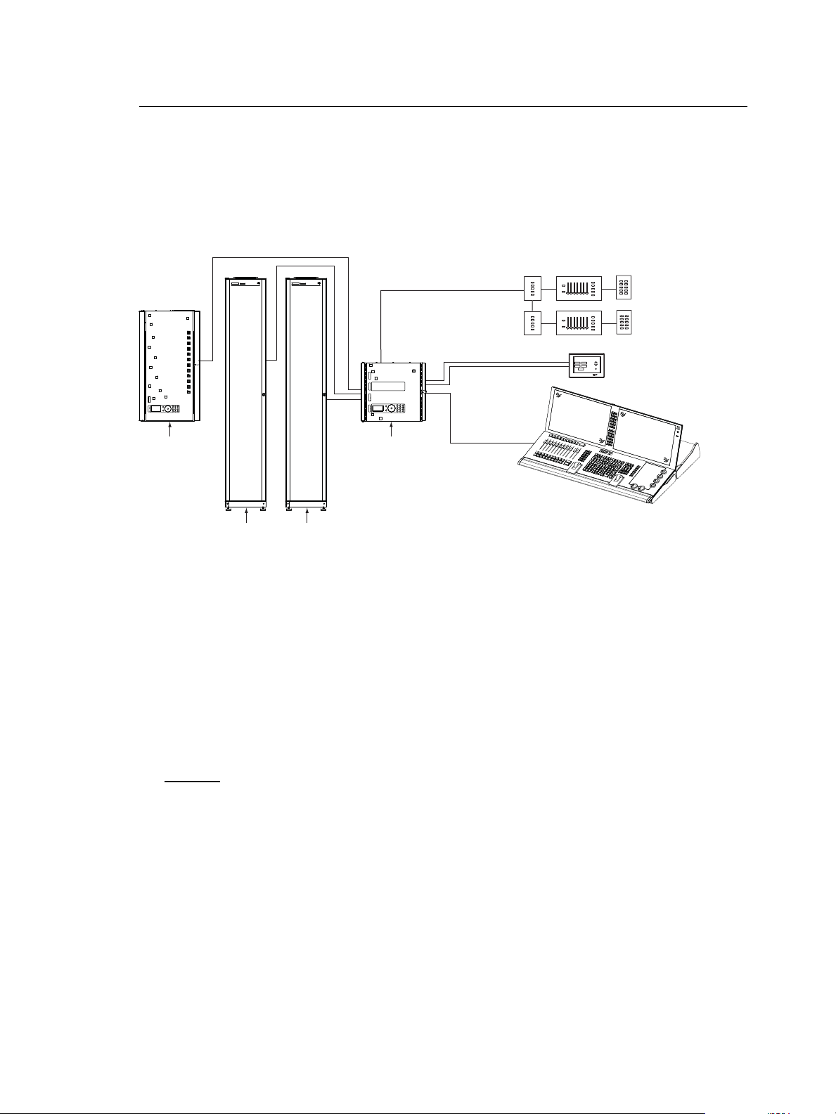
The Echo Architectural Control Processor (E-ACP) is just one component of the Echo
system. The Echo ACP integrates the DRd rack with other Echo networked products (up to
15 other host products such as Sensor 3, Echo Relay Panel, other Echo ACPs) over the
EchoConnect network and supports Echo Inspire stations (up to 16) when station power is
supplied.
Unison DRd12
rack enclosure
SYSTEMLORTNOCGNIHGIL T SYSTEMLORTNOCGNIHGIL T
SENSOR+
SR48+
dimmer rack
SENSOR+
SR48+
dimmer rack
Unison ERn4
processing rack
LinkPower
LinkPower
Aux Power 24 Vdc
console
Sequence
Macro Record
Unison Heritage
Stations
Sequence
Macro Record
Unison Paradigm
Touchscreen LCD
Preset 1
Preset 2
Preset 7
Preset 2
Preset 8
Preset 3
Preset 3
Preset 9
Preset 4
Preset 4
Preset 5
Preset 10
Preset 5
Preset 1
Preset 6
Preset 1
Preset 2
Preset 7
Preset 2
Preset 8
Preset 3
Preset 3
Preset 9
Preset 4
Preset 4
Preset 5
Preset 10
Preset 5
Preset 1
Preset 2
Preset 3
Preset 4
Preset 5
Preset 1
Preset 2
Preset 3
Preset 4
Preset 5
Eos Ti
Preset 1
Preset 6
power
feed
power
feed
DMX input
to ERn rack
ETC Console
(for optional stage lighting)
power
feed
power
feed
With the integrated control, the Echo ACP is a powerful interface allowing:
• dimming system configuration - simple setup using the Quick Rack Setup menu or
custom setup using the Dimmer Setup menu.
• preset, spaces, zones and sequence control - supports 64 internal presets (recording
of and playback), 8 spaces on the E-ACP or 16 spaces per Echo system, 16 zones per
space, and a single sequence per space
• control priority - supports configuration of control priorities (DMX and Arch control)
• UL 924 Emergency configuration - simple configuration of emergency from the E-ACP
using a master level and load-shedding (the emergency input is controlled separately
by the DRd)
Dimmer
A dimmer refers to the physical position or the logical reference number of a module in the
enclosure, used to refer to the controllable output in the DRd enclosure.
Depending on the host rack type, either DRd 6, DRd 12, or dual DRd 12 with an Auxiliary
rack, there could be anywhere from 12 to 48 circuits available per Echo ACP which can be
populated with a module of any variety including:
• universal dimmer modules - which control incandescent, magnetic low-voltage, twoand four-wire fluorescent, neon, cold-cathode, or switched loads
• specialized modules - such as three-wire fluorescent, relay, or constant current.
• electronic low-voltage dimming modules available for reverse-phase (trailing edge)
dimming of electronic transformer loads.
Introduction 4
Page 10

When configuring your DRd, using the Dimmer Setup menu, you must assign each dimmer
to a Space.
Spaces
Spaces are logical divisions within a system that isolates station control (preset and
sequence control) to the defined group of controllable outputs in that division. A single Echo
ACP is limited to 8 spaces, and an Echo system supports up to 16 spaces.
Each space must be configured using the Space Setup option in the Arch Setup menu.
When configuring your DRd, using the Dimmer Setup menu, you must assign each dimmer
in the enclosure to a Space.
Circuit
A circuit is the logical reference number used to talk about the controllable output in the
Echo ACP. Circuits should be configured to be unique within a space and are user
configurable in the Dimmer Setup menu for the selected dimmer. A circuit can be any user
configured number from 1 to 65535.
The combination of space and circuit can provide a unique identification of an output in a
system.
Zone
Zones are controllable entities within an Echo system, used to logically group the
controllable outputs (dimmers) for control from a connected Echo Inspire station.
One or more dimmers can be assigned to a single zone using the Dimmer Setup menu for
the selected dimmer. Each zone level may be individually manipulated through use of a
connected Echo Inspire station and the zone can be assigned to an Echo Inspire station for
direct control using that stations function selector switch. Reference the Echo Inspire
Station Installation Guide for information.
Arbitration
The Echo ACP can accept a variety of control sources including DMX input, Streaming ACN
(sACN), presets, sequence, manual set levels, and panic.
Circuit output arbitration is based on the sACN model of source priority, meaning each
source is assigned a priority between 1 and 200 (200 is the highest priority). With this
priority, control sources are arbitrated based on their set priority. The Echo ACP default
priority is 100. Control sources at equal priority will HTP or are arbitrated by Highest Takes
Precedence.
The Echo ACP uses the priority assigned within the sACN packet, sent from the control
source and sets the configured priority for DMX, presets, and sequence.
Manually set levels from the user interface of the Echo ACP overrides all other control
sources with the exception of panic. Panic is the highest possible priority.
Configuration
The Echo ACP features a dynamic user interface with a touch wheel for easy menu
navigation, an numeric button pad for direct selection, and a bright, easy to read graphic
LCD.
All setup and configuration are accomplished from the Echo ACP user interface. No
external software is required. Echo Inspire station configuration is accomplished through
rotary switches on the station electronics.
Backup
The Echo ACP front panel features a Secure Digital (SD) media card slot and a USB port
for use of a flash drive. Use any compatible removable media to backup your configuration
files, load a new configuration, or update the Echo ACP firmware. See Removable Media,
page 14 for a list of compatible media.
5 Echo ACP Configuration Manual
Page 11

Rack and System Feedback
The Echo ACP provides feedback through the status indicators on the front panel of the
Echo ACP. Each indicator is visible from the front panel of the Echo ACP with the DRd
enclosure door closed. Additional status information is provided on the front panel of the
Echo ACP display.
Additional status information is provided on the front panel of the Echo ACP display.
• By default, the “Dimming Rack Status” displays. Rack status includes information
pertaining to DMX addressing, rack phase voltage, frequency settings, rack
temperature and embedded dimming engine software version number.
• Clockwise rotation on the touch wheel changes the status display to “Arch Control
Status”. “Arch Control Status” includes information pertaining to the Echo processor
including the processor IP address, DMX port configuration, activity, host rack type and
Echo software version number.
Control Inputs
Left I/O
The Left I/O board on the DRd enclosure is an optional accessory that provides an Ethernet
(IEEE 802.3) connection to the DRd with Echo ACP. This networks the DRd dimming
system with other Ethernet sACN based control systems.
Introduction 6
Page 12
Right I/O
SIGNAL DISTRO
RIDE THRU/BATT
J9
DUAL RACKS
LPS
APM
DMXB
AUX POWER
LON LINK / ECHO BUS
CDI
DMXA
B+ B- COM A+ A- COM
7183B4606 REV F © 2013 ETC, INC. MADE IN THE U.S.A.
B+ B- COM
COM PANIC
A+ A- COM
DMXB DMXA
SRC OFF END
DMX PASS-THRU
DRd right I/O
• EchoConnect Station Bus - station
communication bus from the Echo
ACP to the Echo control stations and
other products.
• DMX (Digital Multiplex) - addresses up
to 512 channels of control. The Echo
ACP supports one universe of DMX
input. DMX through connections are
available for use as needed. The
DMXB connector is not used.
• Optional accessory connections
include Battery Backup, Com / Panic
input, and Dual Racks (used only if an
Auxiliary rack is installed).
The Right I/O board on the DRd enclosures provide a majority of the control inputs into the
system including:
Note:
Older Right I/O boards not marked with “LON/Link / Echo Bus” are not compatible
for operation with the Echo ACP and EchoConnect wiring. Contact ETC Technical
Services about obtaining an upgrade kit.
Additional detail for connections found on the Right I/O boards are detailed in the related
Unison DRd Enclosure Installation Manual.
7 Echo ACP Configuration Manual
Page 13
Installation Environment Requirements
The Echo ACP is designed for use in a Unison DRd enclosure. The environmental
conditions for the Echo ACP should adhere to the requirements set for the DRd enclosure.
Reference the Unison DRd Rack Enclosure Installation Manual for complete details.
• A clean (not dusty) temperature-controlled environment with an ambient temperature
of 32-104°F / 0-40°C and ambient humidity of 10-90%, non-condensing.
• Restricted public access to prevent tampering.
• Soundproofing or performance area separation to muffle ventilation fan noise is
recommended.
• All CE equipment is tested to EMC category B environment.
CAUTION:
Installation of the Echo ACP is as simple as sliding the module into the bottom guided slots
of the enclosure. See “Install the Echo ACP” on page 15. There are no wire terminations
made directly to the Echo ACP, instead all wire terminations are made to the host DRd
enclosure left and right I/O boards. Reference the Unison DRd Rack Enclosure Installation
Manual for complete wire termination details.
Compliance
• UL and cUL Listed
• CE Compliant
HVAC systems must at all times maintain the specified ambient temperature at the
rack. Dimming systems operating within 10°F (5°C) of the upper or lower
temperature limits must strictly follow installation and operation guidelines to
operate reliably.
Introduction 8
Page 14

9 Echo ACP Configuration Manual
Page 15

Chapter 1
UI Overview and Installation
This chapter contains the following sections:
• User Interface Overview . . . . . . . . . . . . . . . . . . . . . . . . . . . . .11
• Install the Echo ACP . . . . . . . . . . . . . . . . . . . . . . . . . . . . . . . .15
1 UI Overview and Installation 10
Page 16
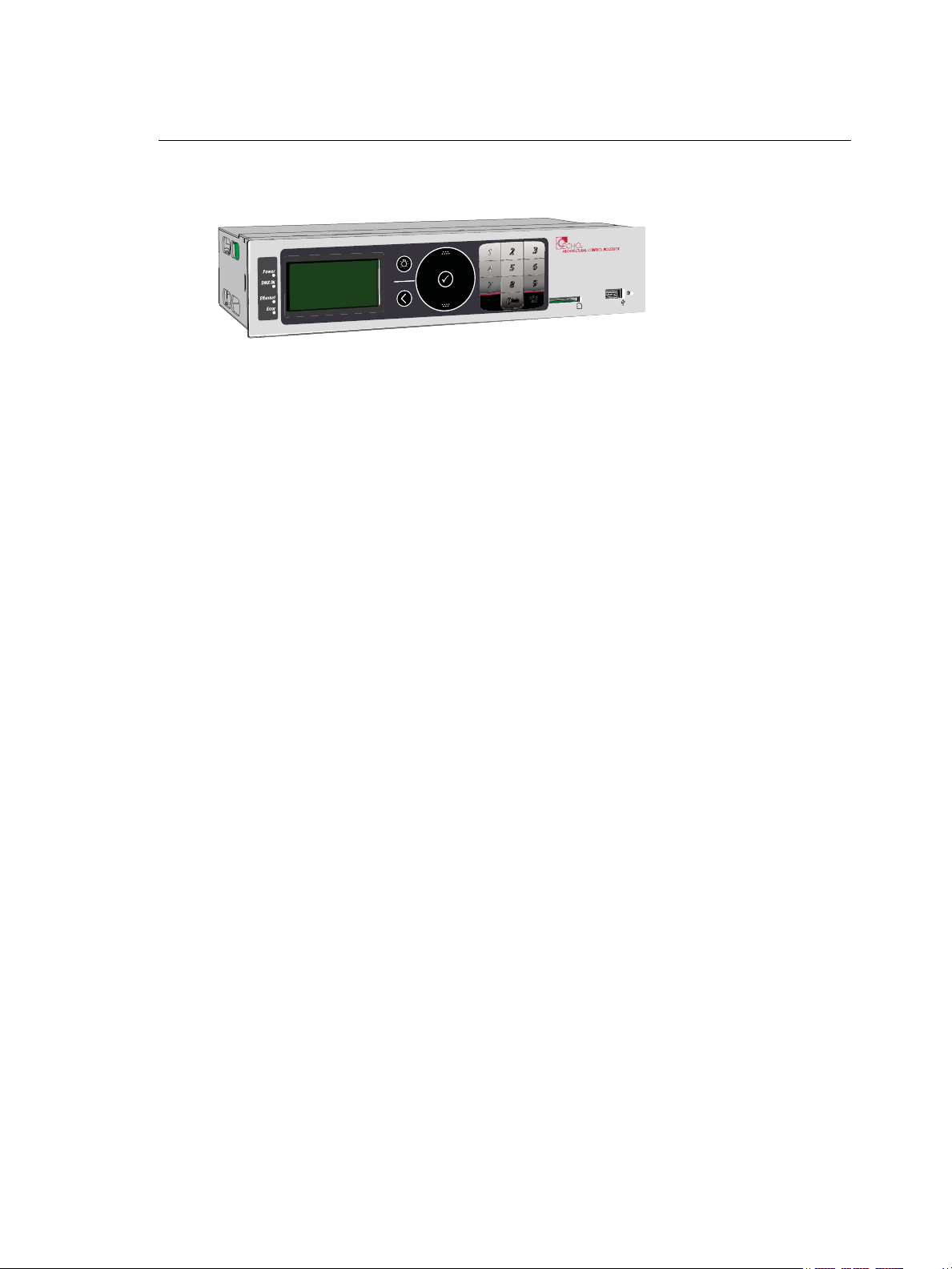
User Interface Overview
1 About
2 Dimming Setup
3 Arch Setup
4 Dimming Control
5 Arch Control
6 File Operations
7 View/Clear Errors
8 Restricted Access
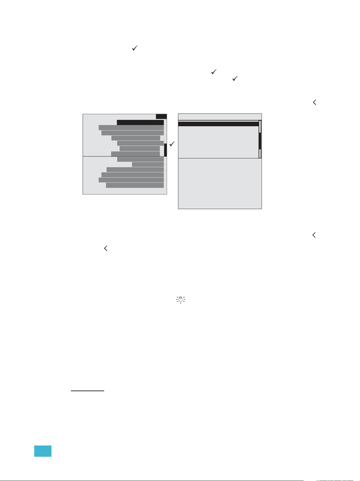
Main Menu
scroll bar
The Echo ACP features a dynamic user interface with a touch wheel for easy menu
navigation, an numeric button pad for direct selection, and a bright, easy to read graphic
LCD. Additionally, an SD media card slot and integrated USB port for flash drive.
LCD Display
The Echo ACP features a backlit LCD capable of displaying 8 rows of text with 21
characters per line. The first row is reserved for the menu title. The last character of rows
two through eight are reserved to display a proportional scroll bar. The scroll bar is visible
only when the menu list requires scrolling to see the entire menu.
Wake
The menu system and LCD backlight are set, by default, to sleep after one minute of
inactivity. Any button press wakes the user interface and LCD backlight. The inactivity time
setting is user selectable from the “Arch Setup” menu. See “Inactivity Time” on page 39.
Settings include 30 secs, 1 min, 5 mins, 15 min, and never.
Touch Wheel
Scroll the menu by moving your forefinger lightly around the touch wheel to highlight a
menu item. You may move your finger clockwise to scroll down the menu list or counterclockwise to scroll up the menu list.
The top and bottom areas of the touch wheel function as buttons for increment and
decrement operations. When navigating through a menu list, you may use these areas to
move up or down the list one menu item at a time. This may also be used to increment or
decrement numerical or selection based edits in certain menus.
11 Echo ACP Configuration Manuall
Page 17
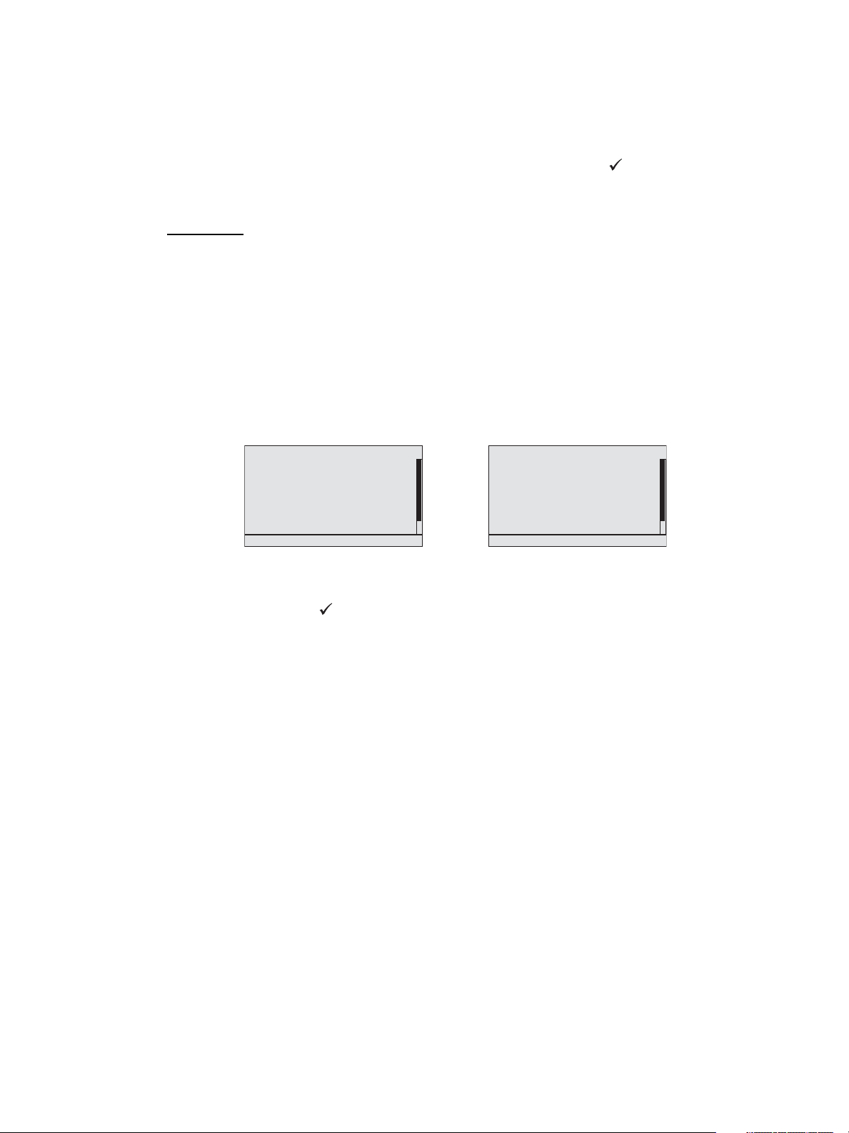
Enter
The enter button ( ) is used to commit an edit or an action such as to make a selection
from the menu list or to commit a selected value.
When focus is on the first text value (“Module Type:” in the example below) and an edit or
change to the selection is desired, press enter ( ). The display changes to select the
Module Type. Scroll to select the type and press enter ( ) to make the selection and
return to the Dimmer Setup menu. Scroll again to change focus to the next selectable
parameter for edit.
When all selections and edits have been made for the display, press the back button ( )
to return to the previous menu.
Dimmer Setup
Module Type: D20
Mode: Normal
Curve: Mod Square
Threshold: 1 %
Voltage Reg: On
Max Scale: 118 V
Min Scale: 6 V
Dyn Preheat: Off
Transformer mode: On
DMX Res: Hi 16 bit
Space: 1
Zone: 1
Circuit: 1
Name: Circuit 1
1
Module Type
D20
D20E
D20F
ELV10
L10
L10F
R15
R20
D15FB
D20FB
AFM
CC15
CC20
D15
D15E
D15F
None
Back
To cancel an entry or selection and return to the previous menu, press the back button ( ).
When selection focus is on a specific value and you cancel the edit by pressing the back
button ( ), focus changes to the previous selectable value.
Multiple presses of the back button will eventually take you to the status display, either the
Dimming Rack Status (DRd only) display or the Arch Control Status display, whichever was
viewed last.
Control Menu Shortcut
The control menu shortcut button ( ) provides easy access to the dimming and
architectural control menus.
Press the control menu shortcut button once to access the dimming control menu. Press it
again to access the arch control menu.
Numeric Button Pad
The numbers on the button pad may be used to select specific menu items when using
#nav shortcuts is enabled, or to enter a specific value such as a dimmer number, intensity
value, etc., while in a selectable menu. Additionally, the button pad may be used to
numerically search the menu. When a “abc” graphic is displayed in the right corner of the
display, numeric searching may be used.
Recentand
The [recent and] button is a dual function button.
• Used as a menu navigation shortcut, pressing [recent/] at any point in navigation
displays a list of the last seven device menus that have been accessed, with the most
recent first in the list. Selecting any of the listed items automatically directs you to that
1 UI Overview and Installation 12
Page 18
menu. Recent command navigation relies on the current user access level to display
1 About
2 Dimming Setup
3 Arch Setup
4 Dimming Control
5 Arch Control
6 File Operations
7 View/Clear Errors
8 Restricted Access
Main Menu
About
Dimming Setup
Arch Setup
Dimming Control
Arch Control
File Operations
View/Cle ar Errors
Restricted Access
Main Menu
only accessible options.
• Alternatively, while navigating certain menu items such as “Dimming Setup” or
“Dimming Control” menus and selecting specific dimmers, use the [and] button to select
dimmers out of sequence. For example, [1] [and] [5] [and] [8] ( ), selects dimmers 1,
5, and 8. Once selected you may use the numeric button pad to add a value to the
selected dimmers or use the touch wheel to scroll to a desired value.
#Nav/Thru
The [#nav thru] button is a dual function button.
• Pressing the [#nav] button toggles the appearance of numbers to the left of menu
items. When numbers are visible, pressing a number selects and enters into the
corresponding menu item. This is called number navigation (#nav).
• Pressing the #nav button starts a number navigation command. Most number
navigations use only two numbers (e.g. [#nav] [1] [3] for “Version Info”). The #nav
button must be pressed first to initiate each shortcut (when the numbers are not
already visible). If an incomplete command leaves the numbers visible until the
inactivity timeout occurs, the #nav command is cancelled. See “Inactivity Time” on
page 39.
• Alternatively, press the [thru] button while in certain menu items such as “Dimming
Setup” or “Dimming Control” menus to select a range of dimmers. For example,
[1] [thru] [1][0] ( ), selects dimmers 1 through 10. Once selected you may use the
numeric button pad to add a value to the selected dimmers or use the touch wheel to
scroll to a desired value.
13 Echo ACP Configuration Manuall
Page 19
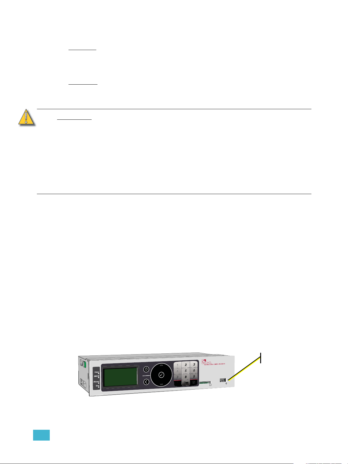
Removable Media
reset switch
USB Port
The Echo ACP includes a USB port for use with a flash drive, located on the front panel.
The USB flash drive is not included and can be purchased separately. A USB flash drive
can be used to store and load backup files of your architectural and dimming configurations.
SD Media
The Echo ACP includes a Secure Digital (SD) media card slot located on the front panel.
The SD media card is not included and can be purchased separately. Use a compatible SD
card to store and load backup files of your architectural and dimming configurations.
CAUTION:
To insert a compatible SD card into the ACP SD card slot -
The SD card is small and rectangular in shape with a notched corner on the front right side.
Gently press the card into the slot, face side up with the notch on the right, until you hear
an audible click and the card end is flush with the front panel of the Echo ACP. Reference
the File Operations Menu for instructions to save or load configuration files.
To remove a compatible SD card from the ACP SD card slot -
Once the save or upload process is completed, gently press the end of the card until you
hear an audible click and the card releases from the slot.
Format the SD media card
2GB SD cards may utilize several different file storage systems. Some of these
systems are not compatible with the Echo ACP. It is recommended that 2GB SD
cards not be used with the Echo ACP.
The following related memory card types are incompatible with the Echo ACP,
even if they fit the form factor of the SD card slot:
• Multimedia Memory (MMC) card
• miniSD card
• MicroSD card with or without adaptor
• Transflash card with adaptor
Most SD media is pre-formatted with the correct file system. When needed you can format
the SD card yourself using a PC with Windows
computer with a SD card reader. Reference the related operating system help for
instructions to format a SD media card.
®
operating system or an Apple® Macintosh®
Reset Switch
Reset the Echo ACP software and hardware by pressing the reset switch located on the
front panel of the unit. Access the reset switch using the tip of a ball point pen, or other
pointed object.
During a powered reset the dimming engine holds the levels for the last played preset or
event until the ACP has rebooted.
1 UI Overview and Installation 14
Page 20
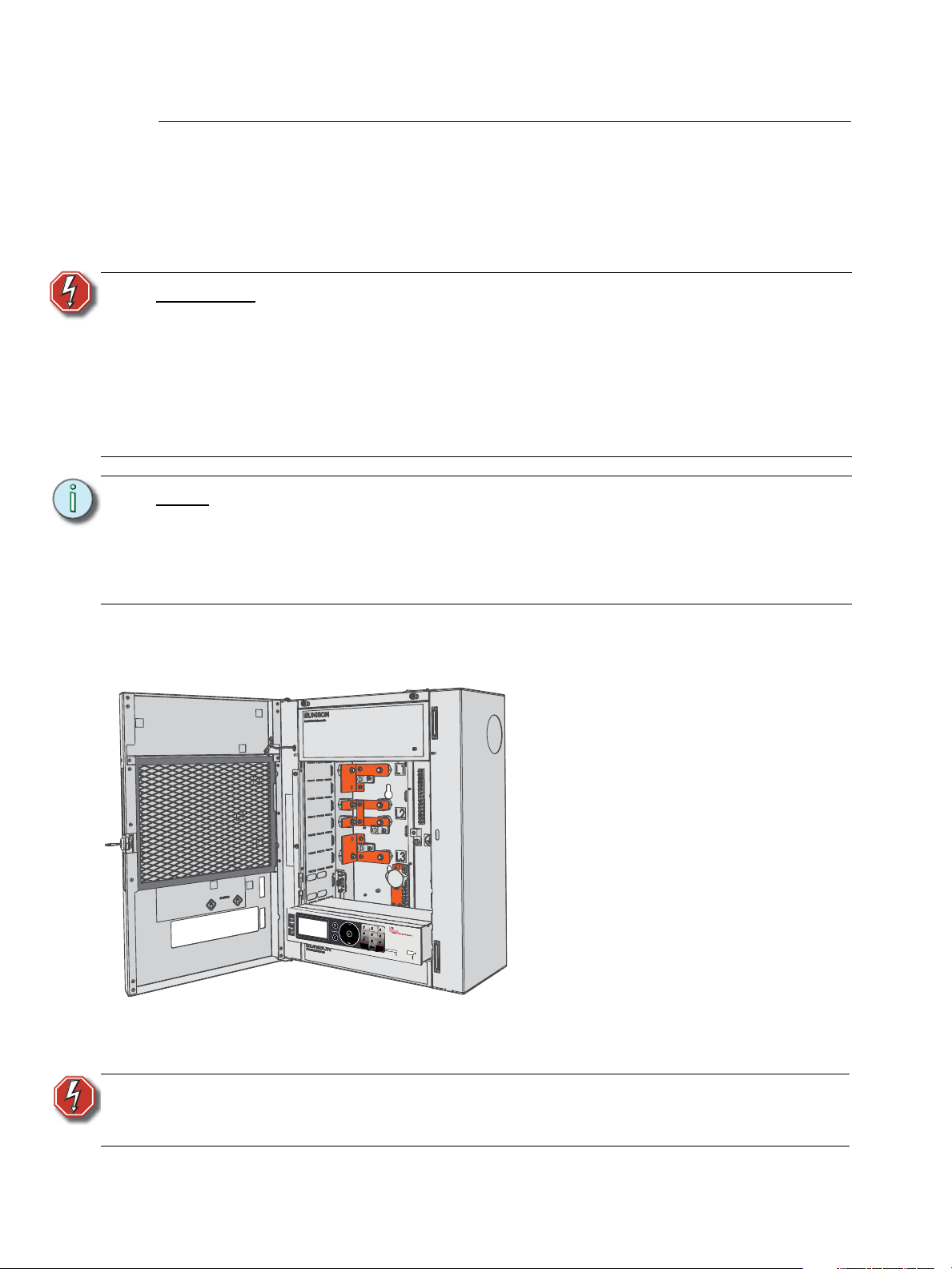
Install the Echo ACP
Step 3: Slide the Echo ACP into the rack.
Step 4: Press gently on each corner of the
processor to ensure proper
connection with the card edge
connectors on the left and right I/O
boards.
Step 5: Install the remaining dimmer
modules into their corresponding
module slots.
Step 6: Slide the module retention bar to
the right and tighten the screws to
secure it in place.
Step 7: Close the DRd enclosure door and
follow the final installation and
power up procedures defined in the
DRd Enclosure Installation Manual.
When power is applied, the status
LEDs will illuminate and the ACP
will load the operating software.
The Echo ACP is designed to slide in the bottom module slot of a Unison DRd enclosure.
All data terminations used with the Echo ACP are terminated to the left and right I/O boards
in the DRd enclosure.
Install the Echo ACP only after the DRd enclosure has been installed and all wires have
been terminated properly.
WARNING:
Note:
Step 1: Open the enclosure door.
Step 2: Rest the Echo ACP on the bottom lip of the enclosure, aligning both left and right
Rack enclosures installed without an accessible power disconnect device
cannot be serviced or operated safely. Follow all local codes and
restrictions. Before installing or removing dimmer or control modules for
service, de-energize main feed to the rack and follow appropriate Lockout/
Tagout procedures as described in NFPA Standard 70E. It is important to
note that electrical equipment such as dimmer racks can present an arc
flash safety hazard if improperly serviced. This is due to available large
Short Circuit Currents on the feeders of the equipment. Any work on
energized equipment must comply with OSHA Electrical Safe Working
Practices.
DRd enclosures are shipped standard with a module retention bar which secures
all dimmer and control modules into the enclosure, requiring a tool for module
removal.
Before installing the Echo ACP module or any other modules, be sure to release
the retention bar first, install the modules, then reengage and secure the retention
bar.
edges with the module slots.
WARNING:
15 Echo ACP Configuration Manuall
Never power up or operate the Unison DRd enclosure without all modules
installed. Failure to comply exposes you to dangerously high voltages that
may result in death by electrical shock.
Page 21

System Status
Dimming Rack Status
System OK
DMX Start = 155
Ø1: 119 Ø2: 119 Ø3: 120
60Hz 102F v5.6.7
Arch Control Status
Preset 15 Active
Sequence Inactive
System OK
DMX Start = 155
DMX Input: Active
DRd12 v1.2.3
• Clockwise rotation on the touch
wheel changes the status display
to Arch Control Status.
• Counter-clockwise rotation on the
touch wheel changes the status
display back to Dimming Rack
Status.
When the Echo ACP is installed and power is applied to the enclosure, the graphic LCD
illuminates and displays Dimming Rack Status.
Check the status LEDs for indication of power, control, and rack status. Each indicator is
visible from the front panel of the Echo ACP with the DRd enclosure door closed.
The following indicators are featured:
• Power LED - indicates on solid when the controller has power
• DMX input status - slow blink when no DMX input is received, fast blink when there is
a data error, on solid when valid DMX input is received.
• Ethernet status - blinks with Ethernet network activity
• Error status - slow blink when errors or warning are present and is off when there no
errors present. The Error LED is accompanied by status messages on the graphic LCD.
See “View/Clear Errors Menu” on page 56.
1 UI Overview and Installation 16
Page 22

17 Echo ACP Configuration Manuall
Page 23

Chapter 2
Echo ACP Basic Navigation
This chapter contains the following sections:
• Status Display . . . . . . . . . . . . . . . . . . . . . . . . . . . . . . . . . . . . .19
• Status / Error Messages . . . . . . . . . . . . . . . . . . . . . . . . . . . . .21
• Menu Navigation . . . . . . . . . . . . . . . . . . . . . . . . . . . . . . . . . . .23
2 Echo ACP Basic Navigation 18
Page 24
Status Display
Dimming Rack Status
System OK
DMX Start = 155
Ø1: 119 Ø2: 119 Ø3: 120
60Hz 102F v5.6.7
The Echo Architectural Control Processor (E-ACP) provides all of the basic rack and
system information on the status display. When the Echo ACP is installed in a DRd
enclosure, the dimming rack status display is the default status display. The architectural
control status display is the only status display available when the Echo ACP is installed in
an ERn enclosure.
DRd Dimming Rack Status Display
• display title - A menu’s title appears in the first row of every display for easy navigation.
• scroll to next display - When the clockwise symbol appears in the display, use the
touch wheel to scroll clockwise to the Arch Control Status display. When the counterclockwise symbol appears, use the touch wheel to scroll counter-clockwise for the
previous display.
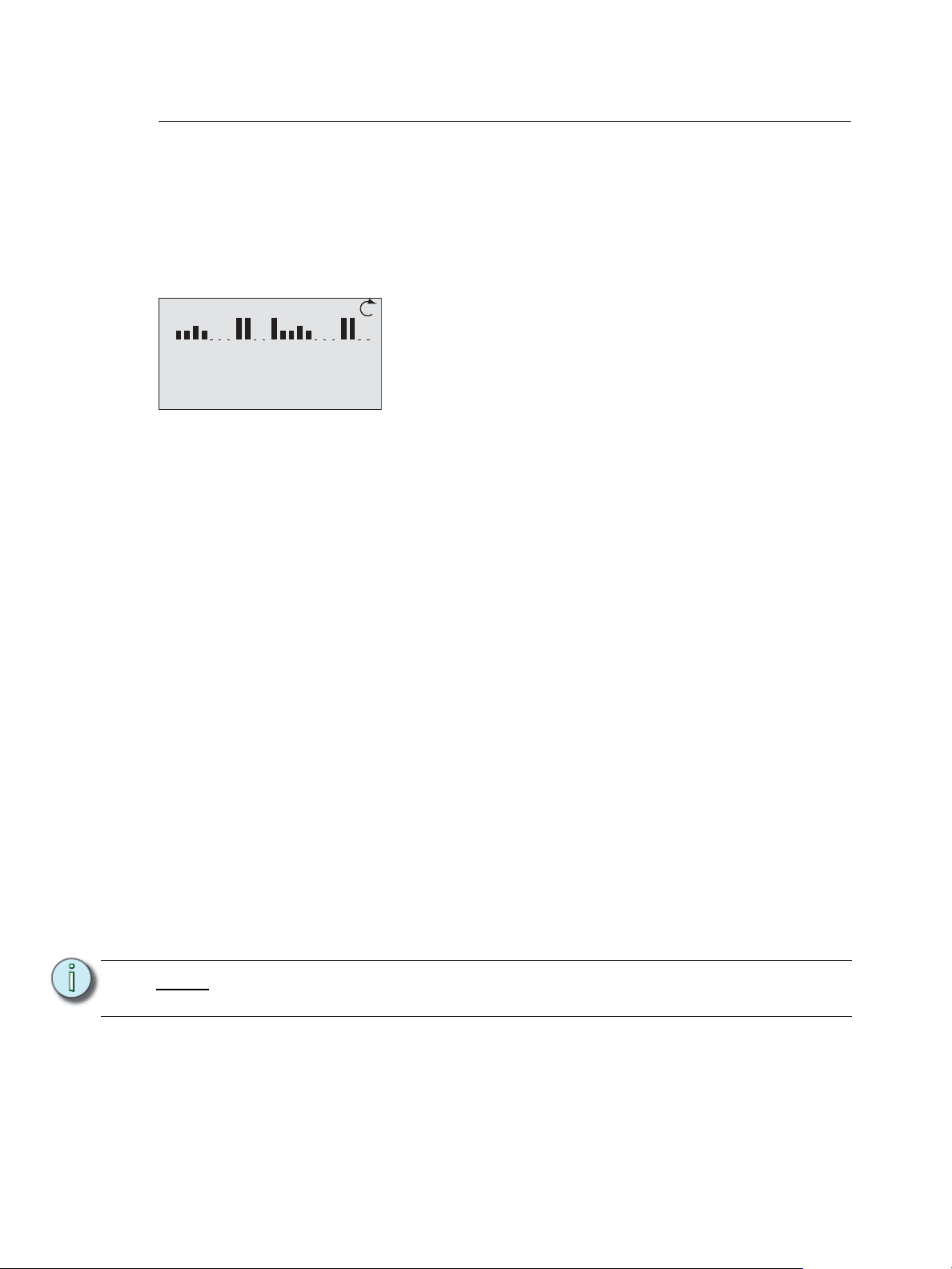
• Rack Dimmer levels - A DRd enclosure with 1 to 24 channels will display all dimmers
with proportional levels on the line beneath the display title (as pictured above). Crossbussed DRd enclosure display dimmers 1-24 on the top line beneath the display title
and dimmers 25-48 on the next line.
Note:
• System Message and Error Display - System messages are common to both the
dimming rack and ACP status displays. When a system error is detected, the message
changes to reflect the specific error type. When multiple errors are detected, each error
message cycles on the display, first by severity and then by chronological occurrence.
Reference Status / Error Messages for a complete listing of possible errors and the
actions required to clear them.
• DMX Start - Indicates the DMX start address of the first circuit in the DRd enclosure.
An equal sign (=) before the address number indicates a 1 to 1 patch of DMX address
to the dimmers in the rack. An approximate equal sign
indicates advanced patching. The DMX value is appended with (bal) when the rack is
configured for 3 phase or 1/bi-phase balanced. Reference the Dimming Setup Menu,
page 27 for details on patching.
• Per Phase Voltage - Each phase of power is measured and represented on the
Dimming Rack Status display. When the rack is configured for bi-phase, only phases 1
and 2 are shown, when the rack is configured for single phase, only the single phase
data is available.
Voltage displayed is a user convenience and is approximate. It is not as accurate
as using proper voltage measurement equipment.
• Operating Frequency, Temps and Dimming software version- Displays the
measured operating frequency and temperature inside the enclosure, and the installed
version of Dimming software. The temperature is shown in °F by default, but can be set
to °C in the Quick Rack Setup menu.
≈ before the address number
19 Echo ACP Configuration Manual
Page 25

• internal operating temperature - The internal operating temperature is measured and
Arch Control Status
Preset 15 Active
Sequence Inactive
System OK
DMX Start = 155
DMX Input: Active
DRd12 v1.2.3
displays on the dimming rack status display. By default, temperature is displayed in °F
when the rack is 120, 240, or 277V AC, and in °C when the rack is 230 V AC.
• rack software version - The rack software is specific to the dimming engine and may
differ from the ACP software version.
Arch Control Status Display
• display title - A menu’s title appears in the first row of every display for easy navigation.
• scroll to previous display - When the counter-clockwise symbol appears in the
display use the touch wheel to scroll counter-clockwise for the Dimming Rack Status
display. When the counter-clockwise symbol appears, use the touch wheel to scroll
counter-clockwise for the previous display.
• Preset status - The second row of information displays presets status, for presets that
are configured and controlled by the host Echo ACP.
• Sequence status and IP Address - The third row of data cycles between displaying
the Echo ACP IP address and the status of built-in sequences. The processor IP
address is set to Automatic IP address by factory default, and is only displayed if an
active Ethernet interface is detected.
• System Message and Error Display - System messages are common to both the
dimming rack and ACP status displays. When a system error is detected, the message
changes to reflect the specific error type. When multiple errors are detected, each error
message cycles on the display, first by severity and then by chronological occurrence.
Reference Status / Error Messages for a complete listing of possible errors and the
actions required to clear them.
• DMX Start: Indicates the DMX start address of the first circuit in the DRd enclosure. An
equal sign (=) before the address number indicates a 1 to 1 patch of DMX address to
the dimmers in the rack. An approximate equal sign
≈ before the address number
indicates advanced patching. The DMX value is appended with (bal) when the rack is
configured for 3 phase or 1/bi-phase balanced. Reference the Dimming Setup Menu,
page 27 for details on patching.
• DMX Input and sACN Input: Cycles between the active status of the DMX input and
the sACN input, when configured.
• Rack type and E-ACP software version - Displays the host rack type, manually set
or automatically detected and the installed version of Echo ACP software.
2 Echo ACP Basic Navigation 20
Page 26

Status / Error Messages
Status messages display on both the dimming rack status display and the Arch Control
Status display. When the Echo ACP is installed in a DRd enclosure, use the touch wheel
to scroll clockwise ( ) to view the Arch Control Status display.
Status messages provide you with system wide, rack specific or even just dimmer specific
information including errors. Important errors may suppress display of other existing errors
on the status display. For a complete list of errors see Status / Error Messages Generated
by the Echo ACP and Status / Errors Messages Generated by the DRd Dimming Engine.
Status / Error Messages Generated by the Echo ACP
Message Displayed Description Action
System OK No errors exist No action required for normal operation.
The programmed Emergency bypass
(Panic) look is played. If load shedding is
Emergency Active
Dimming Firmware /
Mismatch Detected
Dimming Engine
Communication Failure!
ACP and DRd
Configuration Mismatch
AX12X ACP Position
Error
DMX Input Data Error DMX serial error occurred. Verify proper DMX data line termination.
Ethernet/Connection
Lost
Panic/Emergency bypass
operation is active
Firmware version
mismatch between the
DRd enclosure and the
Echo ACP.
The Echo ACP cannot
communicate with the DRd
dimming engine properly.
Occurs when the dimming
configuration stored locally
on the Echo ACP does not
match the configuration
running within the DRd
dimming engine.
An error display warns you
when the Echo ACP is
installed in “Rack 2” of a
cross-bussed application.
Ethernet disconnect,
connectivity was active
then lost.
set to “On” all loads not in emergency are
shed. Also the dimming setup, restore
defaults, load dimming configuration, and
update firmware menus will be locked out
from user intervention.
This is resolved through a firmware
update procedure. See “Update
Firmware” on page 55.
The error is clearable by correcting the
failure point. Contact ETC Technical
Services for troubleshooting assistance
as needed.
The menu locks out additional navigation
and requires you to confirm use of either
the dimming rack configuration or use of
the dimming configuration as stored on
the Echo ACP. Alternatively you can
select “Quick Rack Setup” to create a new
configuration.
Occurs only when the Echo ACP is
installed in a cross-bussed host DRd
enclosure. This error cannot be cleared
except by correctly installing the AX12X
interconnect cable or by moving the Echo
ACP to the enclosure with the
interconnect cable end labeled “Rack 1”.
Troubleshoot Ethernet infrastructure for a
device or cable failure.
21 Echo ACP Configuration Manual
Page 27

Status / Errors Messages Generated by the DRd Dimming Engine
Message Displayed Description Action
Rack Error / Rack
Overtemp
Rack Warning / High
Operating Temp
Rack Warning / Low
Operating Temp
Rack Error/Freq out of
Range
Dimmer Overtemp/
Dimmers ## and ##
Rack Error/Phase 1
Missing
Rack Error/Phase 2
Missing
Rack Error/Phase 3
Missing
Rack Error/Phase 1
Overvoltage
Rack Error/Phase 2
Overvoltage
Rack Error/Phase 3
Overvoltage
Rack Error/Phase 1
Undervoltage
Rack Error/Phase 2
Undervoltage
Rack Error/Phase 3
Undervoltage
Rack Error/Fan Error or
Failure
Ambient temperature is
above rated temperature
range.
Ambient temperature is
approaching maximum
temperature.
Ambient temperature is
below rated temperature
range.
Input power frequency is
out of operating range.
Dimmer is in an overtemp
condition.
Phase A is off. Check mains power feed.
Phase B is off. Check mains power feed.
Phase C is off. Check mains power feed.
Phase A voltage is above
rated voltage range.
Phase B voltage is above
rated voltage range.
Phase C voltage is above
rated voltage range.
Phase A voltage is below
rated voltage range.
Phase B voltage is below
rated voltage range.
Phase C voltage is below
rated voltage range.
Fan is not operating
properly.
All dimmers in the enclosure are disabled
from use until the ambient temperature is
within an acceptable operating range.
Correct the ambient temperature to within
specification.
Correct the ambient temperature to within
specification.
All dimmers in the enclosure are disabled
from use until the input power frequency is
within acceptable operating range.
The specified dimmer automatically
disables. Verify loads are within
acceptable limits. Try swapping dimmer
modules to isolate if the problem is within
a module.
All dimmers in the enclosure are disabled
from use until Phase A voltage is within
acceptable operating range.
All dimmers in the enclosure are disabled
from use until Phase B voltage is within
acceptable operating range.
All dimmers in the enclosure are disabled
from use until Phase C voltage is within
acceptable operating range
Correct input voltage to acceptable range.
Correct input voltage to acceptable range.
Correct input voltage to acceptable range.
Verify that the fan is not obstructed.
2 Echo ACP Basic Navigation 22
Page 28

Menu Navigation
The Echo ACP menu is designed with consistent navigation from the user interface either
using the numeric button pad or the touch wheel.
Note:
To navigate the menu using the numeric button pad, press the #nav/thru button
on the button pad. This enables number navigation and displays the specified
numbers to the left of an existing menu list. See “#Nav/Thru” on page 13.
The main menu is the root for all menu navigation. When a menu item is selected from the
main menu, a secondary menu displays including multiple functions for selection.
When a menu item is selected, an operation menu displays for your action or edit of objects.
Operations for your action and/or edit use descriptive text which is followed by a colon “:”
and a value.
The numeric button pad or the touch wheel may be used to edit specific objects from the
operation menu, such as dimmer number, levels, etc. Once an edit has been made, press
the enter ( ) button to accept the selection.
Use the touch wheel to navigate to the next object for action or edit. To return to the
previous operation, press the back ( ) button. Continue pressing the back ( ) button to
return to the menu list and eventually the main menu.
The back ( ) button may also be used with any “Yes” or “No” dialog box. Pressing the back
( ) button is similar to selecting “No”.
23 Echo ACP Configuration Manual
Page 29

Chapter 3
Programming
This chapter contains the following sections:
• About Menu . . . . . . . . . . . . . . . . . . . . . . . . . . . . . . . . . . . . . . .25
• Dimming Setup Menu . . . . . . . . . . . . . . . . . . . . . . . . . . . . . . .27
• Arch Setup Menu . . . . . . . . . . . . . . . . . . . . . . . . . . . . . . . . . . .37
• Dimming Control Menu . . . . . . . . . . . . . . . . . . . . . . . . . . . . . .43
• Arch Control Menu. . . . . . . . . . . . . . . . . . . . . . . . . . . . . . . . . .45
• File Operations Menu . . . . . . . . . . . . . . . . . . . . . . . . . . . . . . .49
• View/Clear Errors Menu. . . . . . . . . . . . . . . . . . . . . . . . . . . . . .56
• Restricted Access Menu . . . . . . . . . . . . . . . . . . . . . . . . . . . . .57
3 Programming 24
Page 30

About Menu
The “About” menu provides you direct access to view
details about your dimmers, current level summary
data, software version information, and information
about which spaces in your Echo ACP configuration
have combined control.
About Dimmer 1
Current Level: 70%
DMX Level: 45%
sACN Level: 0%
Arch Level: 33%
Set Level: 0%
Panic/Emer: 100%
<push Enter for more>
Dim Ckt Src Level
1 1 DMX 255
2 24 sACN 128
3 3 Arch 75
4 4 --- --5 5 DMX 255
6 6 Emerg 255
7 7 Set 0
The “Levels Summary” menu shows each dimmer position in the
enclosure as well as the associated circuit number, the winning
control source, and its actively controlled level (current level)
from the controlling data source for the dimmer.
Levels are displayed in values 0 - 255.
Note:
The “About” menu is provided for you to view information only. There are no
editing tools or menu lists available.
About Dimmer
By default, the “About Dimmer” menu automatically selects and displays the data for the
first dimmer in the rack. Notice the title bar displays the selected dimmer number.
About Dimmer 1
DMX address: 125
sACN address: 1234/123
Module Type: D20F
Mode: Fluorescent
Space: Space 1
Current Level: 70%
<push Enter for more>
Use the touch wheel to scroll to a different dimmer or use the numeric button pad to specify
the dimmer number. Dimmer parameter data updates when a new dimmer is selected.
Press enter ( ) to view additional source details about your selected dimmer. The display
switches between dimmer property and dimmer source data information. To exit the “About
Dimmer menu and return to the previous menu press the back button ( ).
1 About Dimmer
2 Levels Summary
3 Version Info
4 Space Combine
About
Note:
“Current Level” is the actively controlled level from the controlling data source for
this dimmer.
Levels Summary
Valid input control sources include:
• DMX input - displayed as DMX
• streaming ACN - displayed as sACN
• Set levels - displayed as Set
• Preset or Zone levels - displayed as Arch
• Panic/Emergency - displayed as Emerg
• No active control input - displays as ---
Use the touch wheel to scroll through all channels in the list or use the numeric button pad
to specify a channel. To exit the About DMX Level Data menu and return to the previous
menu press the back button ( ).
25 Echo ACP Configuration Manual
Page 31

Version Info
Version Info
Echo ACP App:
12.34.0.0.0.0.05
DRd: 2.1.0.0.0.0.4
FL O: 1.0.0.0.0.0.6
DALI: 1.0.0.0.0.0.7
Echo Protocol:
12.3.5.7.1.1.1
Echo PHY:
12.3.5.7.1. 2.1
The “Version Info” menu displays the current full software
version numbers, including build numbers, for each software
type installed in the rack.
FLO and DALI options only appear if they are presently installed
in the host DRd rack. Each DRd may have only 1 option
installed, except when the rack type is the DRd12AX12X. In this
case, you will notice a “1” or “2” following the software version
type. This indicates to which rack the software relates.
Space Combine
Space 1: 2
Space 2: 1
Space 4: 4-6
Space 5: 4-6
Space 6: 4-6
The “Space Combine” menu displays each configured space for
this Echo ACP and lists other spaces, by their numbers, the
space is combined with for control.
Space 1 is created by default. When no other spaces have been
created, and therefore Space 1 is not combined with anything,
None displays.
Space Combine
Note:
A space cannot be combined with itself.
3 Programming 26
Page 32

Dimming Setup Menu
Dimming Setup
Dimmer Setup
Patch DMX Input
Patch sACN Input
Emergency Setup
Quick Rack Setup
Push to Set Levels
The “Dimming Setup” menu provides a range of options to
setup a host DRd enclosure. Use the “Dimming Setup” menu to
specify dimmer module types, customize dimmer properties,
patch the rack dimmers to the specified DMX input and sACN
input addresses, and setup emergency operation for the
dimmers in the rack configuration.
In the “Dimmer Setup” menu, each dimmer in the rack defaults
to a standard dimmer module (D20, AD20, ED15) depending on
the rack voltage selection and each dimmer module defaults
with standard properties.
Note:
Refer to your architectural panel schedule when patching dimmers to DMX and
sACN inputs.
Dimming setup can be simplified by using the default values as found in the Quick Rack
Setup menu. When viewing the “Dimming Setup” menu, press the control menu shortcut
( ) button to directly access set levels and dimmer check functions.
Dimmer Setup
Dimmer Setup
Module Type: D20
Mode: Normal
Curve: Mod Square
Threshold: 1 %
Voltage Reg: On
Max Scale: 118 V
Min Scale: 6 V
Dyn Preheat: Off
Transformer mode: On
DMX Res: Hi 16 bit
Space: 1
Zone: 1
Circuit: 1
Name: Circuit 1
The “Dimmer Setup” menu provides the ability to set each dimmer’s module type and
properties individually, one dimmer at a time, or set by a range of dimmers using the (and)
and (thru) buttons on the numeric keypad. The range of dimmers cannot exceed the
number of dimmers in the host enclosure.
Each object in the “Dimmer Setup” menu allows you to specify alternative dimmer
properties about each dimmer channel including the dimmer module type, the mode of
operation, curve, etc. Refer to Dimmer Module Defaults, page 65 for a listing of standard
dimmer properties.
1
27 Echo ACP Configuration Manual
Note:
When specifying a range of dimmers, properties that are not equal among the
selected dimmers will display as empty property fields. Any edits made to the
empty property fields are applied to the entire selected range of dimmers.
Specifying a different module type defaults all dimmer properties for the selected
range.
Step 1: Scroll to select a dimmer or use the numeric keypad to specify a range of
dimmers. Press enter ( ) to edit the selected dimmer properties.
Step 2: Scroll to “Module Type” property and press enter ( ). The “Module Type” menu
will display all possible dimmer module types available for the host rack and
voltage.
Step 3: Scroll to select the desired module type from the available list and press enter
( ). The display returns to Dimmer Setup.
Page 33

Note:
Mode
Normal
Dimmer Doubled
Switched
2/3 Wire Fluorescent
Always On
Off
4 Wire Fluorescent
DALI
Reverse Phase
LED Smoothing Fwd
LED Smoothing Reverse
Reference Dimmer Modes, page 68 for
detailed information regarding standard
dimmer firing modes.
Each module type has a default set of properties such as the firing mode, dimmer
curve, etc. When changing a module type, all dimmer properties for the specified
dimmer(s) also change to match the new module type property defaults. You may
edit the dimmer properties individually. Refer to Dimmer Module Defaults, page 65
for a listing of standard dimmer properties.
Step 4: Scroll to “Mode” property and press enter ( ). “Mode” displays for selection.
• Reverse Phase and LED Smoothing Reverse modes display as a selectable
mode only when the “Module Type” is ELV or when using reverse phase
controlled module types such as the ELV10, HELV5, AELV5, EELV6.
• Dimmer Doubled Mode when the rack type is DRd48 with an Auxiliary Rack
or the rack voltage is 240V, Dimmer Doubled is not displayed for selection.
• When Dimmer Doubled Mode is selected, properties for Transformer Mode
and DMX Res are read only.
• Fluorescent modes are abbreviated in the Dimmer Setup display, but are
displayed properly in the Mode selection display.
Step 5: Scroll to select the firing mode for the selected dimmer from the available options
in the list then press enter ( ). Changing the dimming firing mode
automatically changes the default settings for curve, threshold, voltage
regulation, minimum voltage and maximum voltage.
Step 6: Continue through each of the available dimmer properties, modifying each
property only as needed.
3 Programming 28
Note:
Note:
The listing below identifies relatively important information when setting these
additional properties. Reference Dimmer Properties, page 71 for detailed
information about all dimmer properties.
• When the Voltage Reg: property is set to Off, the Max Scale Voltage property is
not displayed.
• When Dimmer Doubled is the selected firing mode, the DMX Res: property
automatically defaults to “Lo 8 bit”.
• Each dimmer must be assigned to a Space. By default, all dimmers are assigned
to Space 1. Spaces are created in the Arch Setup menu.
• By default, all Zones of Space 1 are assigned to the first 16 consecutive dimmers
in the same Space.
• By default, all Circuit numbers default to match the dimmer number.
• The circuit “Name” is a read only property.
Step 7: Press the back button ( ) to return to the Dimming Setup menu.
When exiting the “Dimmer Setup” using the back button ( ), and the changes
made to dimmers / dimmer properties have affected the rack DMX input patch /
sACN input patch, a dialog will display requesting confirmation.
Select to fix the patch issues through the dialog or press the back button ( ) to
ignore the dialog and return to the “Dimming Setup” menu.
Page 34

Patch DMX Input
Patch DMX Input
1: 111 a 111 b
2: 112 a 368 b
3: N A
4: 113
5: 114 H 115 L
6: 116 a 117 b
DIM DMX
The Echo ACP supports one universe of DMX input patch. A
universe is a group of 512 contiguous control channels. When
using the “Patch DMX Input” menu, addresses may start at one or
any number up to 512 minus the number of dimmers in the
enclosure, depending on the type of enclosure(s) you are
programming.
The highest DMX address for any dimmer allowed is 512.
By factory default, dimmers are patched 1 to 1. This means that dimmer 1 is patched to
DMX input address 1, dimmer 2 is patched to DMX address 2, and so on. A basic DMX input
patch is also possible using the Quick Rack Setup menu.
Patch DMX Input Display Features
• “---” is displayed when a dimmer is not patched to a DMX address.
• Dimmers set for Dimmer Doubled mode, Hi 16 bit (DMX resolution), Lo 8 bit (DMX
resolution) operation from the Dimmer Setup menu, require two channels of control
(two DMX addresses). These channels are represented in the Patch DMX Input display
with an “a” and “b”, “H”, or “L” respectively next to the DMX input addresses.
• A dimmer set for Dimmer Doubled mode is by default applied a +256 address offset
from the starting address for the second (b side) control channel value of that
dimmer. For example if dimmer 1 is set to Dimmer Doubled mode and DMX
address 1, the second channel of control (b side) for dimmer 1 would be DMX
address 257.
Note:
Note:
When the result of the Dimmer Doubled offset is greater than the allowable 512
addresses, the A side and the B side of the dimmer are set equal address values.
• A dimmer set for Hi 16 bit is by default applied a +1 address offset from the starting
address for the second control channel value of that dimmer. For example if
dimmer 2 is set to Hi 16 bit and DMX address 501, the second channel of control
for dimmer 2 would be DMX address 502, by default.
When the result of the offset is greater than the allowable 512 addresses, the
dimmer will be unpatched. These addresses will then display as “---”, meaning it
is unpatched.
• When a dimmer is not patched to a DMX address or DMX address 0 is entered, “---” is
displayed.
• When the dimmer module type has less than two controllable addresses (for example
CC20, D20F), “NA” displays for any non-editable dimmer.
29 Echo ACP Configuration Manual
Page 35

Patch Dimmers
Using “and”
Using “thru”
Patch sACN Input
1: 111 a 111 b 63999
2: 112 a 368 b 1
3: N A
4: 113 1
5: 114 H 115 L 1
6: 116 a 117 b 2
DIM sAC N Univ
The Echo ACP manages all sACN inputs-to-dimmer patch
addressing for the enclosure.
A maximum of 4 sACN universes are supported, which can be
arbitrated between a maximum of 6 sources in all.
You may use “and thru” functions to specify a selection or range of dimmers for patch
editing. Once your selection is made, press enter ( ) to accept the selection and begin
editing. To remove the last selected dimmer from the selection, press the back button ( ).
Continue pressing the back button ( ) to clear all undesired dimmers from the selection.
Step 1: Make a selection of dimmers for patching using either the touch wheel or the
numeric button pad. Press enter ( ) to accept the selection.
• In the examples below, the start address for a dimmer range selection is
highlighted and ready for editing. Each additional dimmer added to the
selection using the “and thru” functions adds to the selection. When a hiresolution Hi 16 bit dimmer is selected, both the high and low addresses are
selected for editing.
Patch DMX Input
DIM DMX
1: 111 a 111 b
2: 112 a 368 b
3: N A
4: 113
5: 114 H 115 L
6: 116 a 117 b
Patch sACN Input
DIM DMX
1: 111 a 111 b
2: 112 a 368 b
3: NA
4: 113
5: 114 H 115 L
6: 116 a 117 b
1 AND 3
DIM DMX
1: 111 a 111 b
2: 112 a 368 b
3: NA
4: 113
5: 114 H 115 L
6: 116 a 117 b
1 AND 3 THRU 6
Step 2: Assign a DMX address to the first dimmer in the selection using the scroll wheel
or the numeric keypad, the press enter ( ). The focus changes back to the
dimmer number.
• Assigning a DMX address to the first selected dimmer automatically assigns
consecutive numbering to the remaining selected dimmers based on the first
entry of the selection.
• When dimmer doubling is enabled for a selected dimmer, the focus changes
to the second address (b) selection for the affected dimmers.
Step 3: As needed, assign a DMX address to the second address (b) of the dimmer
doubled dimmer in the list and press enter ( ) to accept the selection. The focus
changes back to the dimmer number.
Note:
3 Programming 30
For example, assume the system is configured with 4 sACN universes (named 1, 2, 3, and
4, configured in the Arch Setup > Network Settings menu).
If two sources are available for universe 1, and two sources for universe 2, and 2 sources
for universe 3, nothing is controllable on universe 4 until one of the other six sources goes
away.
sACN patch editing only allows specification of the 4 sACN universes configured
for this Echo ACP. sACN 1 is available by default, the valid range is 1 - 63999. To
associate sACN universes to this Echo ACP, reference Network Settings, page
41.
Page 36

A universe is a group of 512 contiguous addresses. When using the “Patch sACN Input”
Emergency Dimmers
Emergency Level: 100
Load Shedding: On
Input Type: Maintained
Active When: Closed
Emergency Setup
The “Emergency Setup” provides access to the setup and
operation of dimmers when the integrated emergency bypass
operation is triggered. This operation is UL 924 Listed.
menu, addresses may start at one or any number up to 512 minus the number of dimmers
in the enclosure, depending on the type of enclosure(s) you are programming.
Patch sACN Input
You may use “and thru” functions to specify a selection or range of dimmers for sACN patch
editing. Once your selection is made, press enter ( ) to accept the selection and begin
editing. To remove the last selected dimmer from the selection, press the back button ( ).
Continue pressing the back button ( ) to clear all undesired dimmers from the selection.
Step 1: Make a selection of dimmers for sACN input patch using either the touch wheel
or the numeric button pad. Press enter ( ) to accept the selection.
Step 2: Assign a sACN input address to the first dimmer in the selection using the scroll
wheel or the numeric keypad, the press enter ( ). The focus changes to the
Universe number.
• If the selected dimmer is in dimmer doubled mode, the focus changes to the
second address (b) side of the dimmer.
a: As needed, assign a sACN input address to the second address (b) of the
dimmer doubled dimmer in the list and press enter ( ) to accept the
selection. The focus changes to the Universe number.
Step 3: Use the scroll wheel to select among the sACN Universes that have been
configured for this Echo ACP (refer to Network Settings, page 41).
Emergency Setup
Emergency Dimmers
31 Echo ACP Configuration Manual
The DRd enclosure detects a contact input and immediately triggers the panic/emergency
preset prior to processing any control levels, regardless of the condition of the enclosure
(physical, configuration, or firmware).
Emergency operation uses the emergency settings that are provided by the dimming
engine, as set in Emergency Setup menu, even if the Echo ACP configuration and the
dimming engine configuration do not match.
When panic is triggered in a DRd enclosure, the following menus are not accessible for
view or edit:
• “Dimming Setup” menu
• “Restore Defaults”, “Load Dimming Config”, and “Update Firmware” menus as found in
the “File Operations” menu.
• The [recent] commands shortcut button
From the Emergency Setup menu, scroll to “Emergency Dimmers” and press enter ( ).
Page 37

“Emergency Dimmers” displays for dimmer assignment.
Assign dimmers to be “On” when the panic input is active and
assign other dimmers to turn off (also known as load-shedding).
Emergency Dimmers
1: On 2: On 3: --
4: On 5: -- 6: -7: On 8: On 9: On
10: -- 11: On 12: On
13: NA 14: NA 15A: On
15B:On 16A:On 16B: On
Settings include:
• “On” which is the default and indicates the dimmer will turn on to the emergency preset
level when the emergency input is active.
• “– –” indicated the dimmer is not in the emergency preset or is “Off”.
• “NA” indicates a dimmer that is not applicable such as the CC20 or the second dimmer
for a single density module.
Note:
Note:
Modules with single density or no density, such as the D20F or CC20 modules, do
not allow edits to the second dimmer position. The second dimmer position
defaults to “NA”.
For example, if the first dimmer in the rack (slot #1) is a D20F, a single density
fluorescent dimmer module, you would notice that dimmer number 1 could be set
to be “On” or “Off” depending on your operation requirements. Dimmer number 2
would be automatically set to “NA”. In this example, setting dimmer 1 to “On” will
include both the switched and the dimmed outputs in the emergency preset.
Step 1: Use the touch wheel or the numeric button pad to select dimmers. You may also
use “and/thru” to specify specific or a range of dimmers. When the dimmer
selection, as seen in the title bar, is longer than the allowed 21 characters, an
ellipsis “...” will display at the beginning of the title bar. Press enter ( ) to accept
the selection. The focus changes to the emergency value field.
Dimmer doubled dimmers are shown with both “A” and “B” dimmers. When you
have selected the dimmer number, the “A” dimmer will be selected only by default.
Use the touch wheel to scroll and select the “B” side of the dimmer.
Step 2: Use the touch wheel to set the dimmer to either “On” or “– –”. Press enter ( )
to accept the selection.
Step 3: Continue until all dimmers are set to the desired value.
Step 4: Press the back button ( ) to return to the Emergency Setup menu.
Emergency Level
The Emergency level is the value that the emergency circuits will activate to when the
emergency panic input is active. The emergency level defaults to 100% but can be set to a
minimum setting of 80%.
Step 1: Within the Emergency Setup menu, use the touch wheel to scroll to “Emergency
Level” and press enter ( ).
Step 2: Use the touch wheel or numeric button pad to change the emergency level to any
value between 0% and 100%. Press enter ( ) to accept the selection.
3 Programming 32
Page 38

Load Shedding
Emergency Setup
Emergency Dimmers
Emergency Level: 100
Load Shedding: On
Input Type: Maintained
Active when: Closed
When the DRd enclosure senses the loss of normal power, it
bypasses the Echo ACP and drives selected emergency load
circuits to the emergency level.
The emergency contact input supports a “Maintained” or
“Momentary” input type configured for Active When: “Open” or
Active When: “Closed”. The default “Input Type” is a
“Maintained”, Active When: closed.
Load circuits not set for emergency can either be turned off (via load shedding “On” setting)
or the DRd dimming engine can continue to allow control levels for the circuits that are
excluded from emergency (via load shedding “Off” setting).
Step 1: Within the Emergency Setup menu, use the touch wheel to scroll to “Load
Shedding” and press enter ( ).
Step 2: Use the touch wheel to change the value for load shedding to “On” or “Off. By
default load shedding is set to “On” and all load circuits not in emergency will turn
off when the contact input is active.
Step 3: Press enter ( ) to accept the selection.
Input Type / Active When
Emergency Setup
Emergency Dimmers
Emergency Level: 100
Load Shedding: On
Input Type: Maintained
Active when: Closed
Step 1: Within the Emergency Setup menu, use the touch wheel to scroll to “Input Type”
and press enter ( ). The “Input Type” menu displays.
Step 2: Use the touch wheel to select either “Momentary” or “Maintained”. Press enter
( ) to accept the selection.
Step 3: Use the touch wheel to scroll to “Active When” and press enter ( ). The “Active
When” menu displays.
Step 4: Use the touch wheel to select either “Open” or “Closed”. Press enter ( ) to
accept the selection.
33 Echo ACP Configuration Manual
Page 39

Quick Rack Setup
Quick Rack Setup
Voltage L-N Auto
Rack Type: Auto
Module Type: D20
Balance:
Straight
DMX Start Addr: 1
sACN Universe: 1
sACN Start Addr: 1
Apply Changes* Only
Quick Rack Setup
DMX Start Addr: 1
sACN Universe: 1
sACN Start Addr: 1
Space: 1
Temp: Auto
Apply Changes* Only
Apply All
The “Quick Rack Setup” menu provides you with easy access to set or edit the most
important dimmer rack properties. Voltage, Rack Type, and Temperature settings are
automatic settings (Auto) provided by the Echo ACP.
CAUTION:
Notice also that rack property defaults have already been made for you and are indicated
in the default menu. Changing any of these settings will affect the entire DRd enclosure.
When a property has been changed, an asterisk “*” will display next to the changed value.
When you have made all property adjustments desired, scroll to the bottom of the menu.
Select “Apply Changes * Only” to save only the changes (indicated with an asterisk*) or
select “Apply All” to save all of the currently displayed settings in the “Quick Rack Setup”
menu.
Voltage L-N
This setting is automatically detected by the Echo ACP and should not need to be changed.
These settings include 100-130, 220-240, and 277V AC.
Step 1: Use the touch wheel to scroll to “Voltage L-N”, press enter ( ) repeatedly to
Step 2: When the desired value is displayed, use the touch wheel to scroll to the next
Rack Type
This setting is automatically detected by the Echo ACP and should not need to be changed.
These settings include DRd6, DRd12 and DRd24.
Use extreme caution when adjusting settings that default to “Auto” as these affect
important aspects of your dimming configuration. For example, the voltage setting
determines which dimmer modules are available for selection.
cycle through the available options.
setup option or scroll to “Apply Changes Only” or “Apply All”. Press enter ( ) to
select.
3 Programming 34
Step 1: Use the touch wheel to scroll to “Rack Type”, press enter ( ) repeatedly to
cycle through the available options.
Step 2: When the desired value is displayed, use the touch wheel to scroll to the next
setup option or scroll to “Apply Changes Only” or “Apply All”. Press enter ( ) to
select.
Page 40

Module Type
Module type allows you to quickly set all dimmers in the DRd rack to a single type. Available
modules are determined by the voltage which is automatically determined at power up.
Reference Dimmer Specifications, page 62 for dimmer module property defaults.
• For a 100-130 V AC dimmer rack, the default is a D20 dimmer module.
• For a 230-240V AC dimmer rack, the default is an ED15 dimmer module.
• For a 277V AC dimmer rack, the default is an AD20 dimmer module.
Step 1: Use the touch wheel to scroll to “Module Type”, press enter ( ). The module
type menu list displays for selection.
Step 2: Use the touch wheel to scroll the module type list, press enter ( ) to make your
selection.
Step 3: Use the touch wheel to scroll to the next setup option or scroll to “Apply Changes
Only” or “Apply All”. Press enter ( ) to select.
Balance
This setting is automatically defaulted to “Straight”. Other settings include “3 Phase Bal” or
“1 Phase Bal”.
Step 1: Use the touch wheel to scroll to “Balance”, press enter ( ) repeatedly to cycle
through the available options.
Step 2: When the desired value is displayed, use the touch wheel to scroll to the next
setup option or scroll to “Apply Changes Only” or “Apply All”. Press enter ( ) to
select.
DMX Start Address
This setting is automatically defaulted to “1”. The start address corresponds to the first
address you wish to patch DRd dimmers in the enclosure. When using the “DMX Start
Addr” setting, addresses may range from 1 to 501 depending on the type of dimmer rack.
The highest DMX address for any dimmer allowed is 512.
A universe of DMX is a group of 512 contiguous control channels. When using the “DMX
Start Address” menu feature, addresses may start at one or any number up to 512 minus
the number of dimmers in the enclosure, depending on the type of enclosure(s) you are
programming.
Note:
Note:
Step 1: Use the touch wheel to scroll to “DMX Start Addr” and press enter ( ) to select.
Step 2: Use the touch wheel to scroll or use the numeric button pad to specify a start
Step 3: Use the touch wheel to scroll to the next setup option or scroll to “Apply Changes
Un-editable dimmers, such as the CC20 module, are not assigned addresses in
this operation.
Dimmer doubled dimmers are, by default, applied a default +256 address offset.
When this results in an address greater than 512, the address for the “B” side of
the dimmer is set to equal the “A” side of the dimmer.
High resolution dimmers are applied a default +1 address offset.
If the selected start address doesn’t allow for unique addresses for each dimmer
in the enclosure (for example a DRd6 with a start address of 506), the dimmers
outside of the allowable range of 512 will remain un-patched.
address. Press enter ( ) to select.
Only” or “Apply All”. Press enter ( ) to select.
35 Echo ACP Configuration Manual
Page 41

sACN Universe
This setting is automatically defaulted to sACN Universe “1”. sACN Universe corresponds
to the input universe of control that the Echo ACP will receive control input from. The valid
range is 1 - 63999.
Step 1: Use the touch wheel to scroll to “sACN Universe” and press enter ( ) to select.
Step 2: Use the touch wheel to scroll or use the numeric button pad to specify sACN
universe. Press enter ( ) to select.
Step 3: Use the touch wheel to scroll to the next setup option or scroll to “Apply Changes
Only” or “Apply All”. Press enter ( ) to select.
sACN Start Address
sACN Start Address corresponds to the first sACN address you wish to patch DRd dimmer.
The DRd always receives its sACN from the network connected sACN control device. This
setting is automatically defaulted to sACN Start Address “1”.
A universe of sACN is a group of 512 contiguous control channels. When using the “sACN
Start Address” menu feature, addresses may start at one or any number up to 512 minus
the number of dimmers in the enclosure, depending on the type of enclosure(s) you are
programming.
Note:
Space
Temp
If the selected start address doesn’t allow for unique addresses for each dimmer
in the enclosure (for example a DRd6 with a start address of 506), the dimmers
outside of the allowable range of 512 will remain un-patched.
Step 1: Use the touch wheel to scroll to “sACN Start Address” and press enter ( ) to
select.
Step 2: Use the touch wheel to scroll or use the numeric button pad to specify the start
address. Press enter ( ) to select.
Step 3: Use the touch wheel to scroll to the next setup option or scroll to “Apply Changes
Only” or “Apply All”. Press enter ( ) to select.
Editing this setting allows assignment of all dimmers in the enclosure to a single Space. By
default, Space 1 is selected. As a result of editing this setting, all dimmers will receive
default and unique circuit numbers for the specified Space. By default, these circuit
numbers are equal to the dimmer number and viewable in the Dimmer Setup menu.
Step 1: Use the touch wheel to scroll to “Space” and press enter ( ) to select.
Step 2: Use the touch wheel to scroll or use the numeric button pad to specify the Space
number. Press enter ( ) to select.
Step 3: Use the touch wheel to scroll to the next setup option or scroll to “Apply Changes
Only” or “Apply All”. Press enter ( ) to select.
This setting is automatically defaulted for you. When the dimmer rack’s voltage is set or
defaulted to 100-130, 240, or 277V AC, “Fahrenheit” will be the default. When the dimmer
rack’s current voltage is set or defaulted to 230 V AC, “Celsius” is the default.
Step 1: Use the touch wheel to scroll to “Temp” and press enter ( ) repeatedly to cycle
through the options.
Step 2: When the desired value is displayed, use the touch wheel to scroll to the next
setup option or scroll to “Apply Changes Only” or “Apply All”. Press enter ( ) to
select.
3 Programming 36
Page 42

Arch Setup Menu
The “Arch Setup” menu items governs how this controller uses
available control sources.
When configuring more than one Echo controller on the
network, these settings must be set to each controller
individually.
Remote Record: Off
Data Source Settings
Data Loss & Power On
Preferences
Space Setup
Network Settings
Arch Setup
Remote Record
Enable or disable remote recording of presets from controls on the EchoConnect station
communication bus in this menu. By default, the remote record feature is disabled (Off).
This setting does not affect the ability of this Echo ACP to record presets for its own loads
from the Arch Control menu.
Step 1: Use the touch wheel to scroll to “Remote Record” and press enter ( ). The
selection changes to the currently selected setting.
Step 2: Use the touch wheel to scroll to change the selection between “On” or “Off”.
Press enter ( ) to select. The selection changes back to “Remote Record”.
Data Source Settings
Data Source Settings menu is provided to specify data source properties such as DMX
input to the Echo ACP, DMX and Arch Priorities.
The Echo ACP can accept a variety of control sources including DMX input, streaming ACN
(sACN), presets, sequence, manual set levels, and panic.
Each source is assigned a priority between 1 and 201 (201 is the highest priority). Each
control source is arbitrated based on the set priority. The Echo ACP defaults the DMX
Priority and Arch Priorities to 100.
Manually set levels from the user interface of the Echo ACP overrides all other control
sources with the exception of panic. Panic is the highest possible priority.
Use the touch wheel to scroll to “Data Source Settings” from within the “Arch Setup” menu.
Data Source Settings menu displays.
DMX Input
Enable or disable the DMX input port to the Echo ACP. By default, the DMX input port is
set to “Enabled”.
Step 1: Use the touch wheel to scroll to “DMX Input” from within “Data Source Settings”
menu.
Step 2: Use the touch wheel to scroll to either “Enabled” or Disabled” and press enter
( ) to select. The selection changes back to “DMX Input”.
DMX Priority
Set the priority level for DMX input. By default, DMX Input is set to priority 100.
Step 1: Use the touch wheel to scroll to “DMX Priority” and press enter ( ). The
selection changes to the currently selected setting.
Step 2: Use the touch wheel, scroll to change the selection to any value between 1 and
201, with 201 being the highest priority. Press enter ( ) to select. The selection
changes back to “DMX Priority”.
37 Echo ACP Configuration Manual
Page 43

Arch Priority
DMX Loss Behavior
Mode: Hold Last Look
Wait Time: Forever
sACN Loss Behavior
Mode: Wait and Fade
Wait Time: 3 min 0 sec
Fade Time: 0 min 3 sec
Power On Behavior
Mode: None
DMX Loss Behavior, sACN Loss Behavior, and
Power On Behavior have default settings which can
be customized to fit your installation. DMX behavior
settings apply to the DMX input port.
Set the priority level for Arch controls including the Echo ACP user interface, presets and
sequence controls, and stations on the EchoConnect network.
Step 1: Use the touch wheel to scroll to “Arch Priority” and press enter ( ). The
selection changes to the currently selected setting.
Step 2: Use the touch wheel, scroll to change the selection to any value between 1 and
201, with 201 being the highest priority. Press enter ( ) to select. The selection
changes back to “Arch Priority”.
Data Loss & Power On
DMX Loss Behavior and ACN Loss Behavior
DMX Loss Behavior and ACN Loss Behavior may be set to “Hold Last Look” or “Wait and
Fade”.
• Hold Last Look - holds any active dimmers at whatever control input levels they were
receiving prior to the loss of data. The last levels are retained until data is restored or
the Echo ACP is reset.
• Wait and Fade - holds the last levels received when the data was lost for a user-defined
amount of time and then fades those input levels to zero intensity using a user-defined
fade time. The default wait time setting is three minutes and zero seconds. The default
fade time setting is zero minutes and three seconds. Wait and fade times can range
from zero minutes and zero seconds to 60 minutes and zero seconds.
3 Programming 38
Step 1: Use the touch wheel to scroll to “Data Loss & Power On” from within the “Arch
Setup” menu and press enter ( ). The DMX Loss Behavior, ACN Loss
Behavior, and Power On Behavior menu lists display. Notice the three settings
are separated vertically on the screen. You cannot select the heading, only the
“Mode” and options from within.
Step 2: Use the touch wheel to scroll to DMX Loss Behavior “Mode:” and press enter
( ) repeatedly to cycle through the options.
Step 3: When the desired value is displayed, and depending on the value selection,
additional setting options may display. Use the touch wheel to scroll to the next
setting option, if there is one, and press enter ( ) or press back ( ) to return
to the “Arch Setup” menu.
When “Wait and Fade” is the mode selection:
a: “Wait Time” and “Fade Time” displays for additional settings. Use the touch
wheel to scroll to “Wait Time” and press enter ( ). The focus changes to
the minutes field.
b: Use the touch wheel or numeric button pad to select the desired “minutes”
value and press enter ( ) to change the focus to the seconds field.
c: Use the touch wheel or numeric button pad to select the desired “seconds”
value and press enter ( ) to accept the new values.
d: Repeat for “Fade Time”.
Step 4: Repeat for ACN Loss Behavior.
Page 44

Power On Behavior
Click Volume: Low
InactivityTime: 1 min
Backlight: Auto
Language: English
Preferences
“Preferences” is a menu list of available settings related to the
Echo ACP user interface such as the touch wheel’s click
volume, inactivity time setting, the backlight time setting before
the backlight dims, and the language setting for the menu.
Preferences stay with the ACP not the configuration file and
therefore only need to be set once.
Power On Behavior may be set to “None”, or configured to execute an action, such as
playing a specific preset or a sequence.
Step 1: Use the touch wheel to scroll to “Data Loss & Power On” from within the “Arch
Setup” menu and press enter ( ). The DMX Loss Behavior, ACN Loss
Behavior, and Power On Behavior menu lists display. Notice the three settings
are separated vertically on the screen. You cannot select the heading, only the
“Mode” and options from within.
Step 2: Use the touch wheel to scroll to Power On Behavior “Mode” and press enter
( ). Follow the on screen choices to make an action selection.
Note:
Preferences
Click Volume
Set the “Click Volume” which plays an audible sound when using the touch wheel to scroll
or the buttons to select.
Step 1: Use the touch wheel to scroll to “Preferences” from within the “Arch Setup” menu
Step 2: Use the touch wheel to scroll to “Click Wheel” and press enter ( ) repeatedly
Step 3: When the desired value is displayed, use the touch wheel to scroll to the next
Selecting “Play Preset” or “Play Sequence” as the behavior mode requires
additional parameter specifications. Only presets and sequence actions that are
assigned to spaces that are pre-configured for this Echo ACP are allowed.
and press enter ( ). The Preferences menu list displays.
to cycle through the options “Low”, “High”, or “Off”.
setup option or press back ( ) to return to the “Arch Setup” menu.
Inactivity Time
39 Echo ACP Configuration Manual
Inactivity time is the specified amount of time after which the user interface times out to the
status display. The inactivity time is also the backlight timer (when backlight is set to Auto)
and the number navigation timer for any unfinished number navigations. Time setting
options include “Never”, “30secs”, “1min”, “5min”, and “15min”. Default is set to “1min”. If
the inactivity timer is set to “Never”, the backlight will time out after one minute.
A wake event (any button press) wakes the main menu and backlighting. Any touch wheel
use wakes the status display and backlighting.
Step 1: Use the touch wheel to scroll to “Preferences” from within the “Arch Setup” menu
and press enter ( ). The Preferences menu list displays.
Step 2: Use the touch wheel to scroll to “Inactivity Time” and press enter ( ) repeatedly
to cycle through the options.
Step 3: When the desired value is displayed, use the touch wheel to scroll to the next
setup option or press back ( ) to return to the “Arch Setup” menu.
Page 45

Backlight
Space Setup
Space Name
1 Space 1
5 Space 5
14 S p ace 14
16 S pace 16
-- U n used
-- U n used
-- U n used
-- U n used
The Echo ACP supports configuration of up to 8 of the available
16 Spaces in an Echo system. Space 1 is available as default.
Space names are defaulted to match the space number. For
example, if 1 is the selected Space, the Space Name will be
“Space 1”.
The backlight setting specifies the performance of the user interface backlight. When the
backlight setting is set to “Auto”, the inactivity timer is also the backlight timer. If the
inactivity timer is set to “Never”, the backlight will time out after one minute.
Backlight settings include:
• “Auto” (LCD dims when the inactivity timer has expired)
• “On (the backlight is always on)
• “Off” (the backlight is always off).
Step 1: Use the touch wheel to scroll to “Preferences” from within the “Arch Setup” menu
and press enter ( ). The Preferences menu list displays.
Step 2: Use the touch wheel to scroll to “Backlight” and press enter ( ) repeatedly to
cycle through the options.
Step 3: When the desired value is displayed, use the touch wheel to scroll to the next
setup option or press back ( ) to return to the “Arch Setup” menu.
Language
The multi-language user interface includes English, Spanish, German and French.
Step 1: Use the touch wheel to scroll to “Preferences” from within the “Arch Setup” menu
and press enter ( ). The Preferences menu list displays.
Step 2: Use the touch wheel to scroll to “Language” and press enter ( ) repeatedly to
cycle through the options.
Step 3: When the desired value is displayed, use the touch wheel to scroll to the next
setup option, or press back ( ) to return to the “Arch Setup” menu.
Space Setup
Step 1: Use the touch wheel to scroll to “Space Setup” from within the “Arch Setup” menu
Step 2: Use the touch wheel to scroll, then press enter ( ) to select a row for Space
Step 3: Use the touch wheel or use the numeric keypad to specify the space number.
Note:
and press enter ( ). The Space Setup menu displays with Space 1 populated
by default.
selection. The focus changes to the Space column.
You will not be allowed to specify a Space number that is currently already
specified. Press enter ( ) to set the selection.
If a configured Space is changed to another number and has dimmers or circuits
assigned to it, a dialog displays for confirmation that you want the configured
circuits reassigned to this new Space. Select “Yes” to reassign configured circuits
to the new Space or select “No” to cancel and return to the previous setup.
3 Programming 40
Page 46

Note:
Netw or k Settings
IP Address
sACN Universes
The “Network Settings” menu provides access to editing and
setup of the Echo ACP IP Address mode and sACN Universes.
The Echo ACP must be assigned an IP Address before it can
communicate over the Ethernet control network.
Communication over the Ethernet network is possible when the
host DRd is installed with the left I/O card (Ethernet).
When exiting the Space Setup display and a space has been changed, and it had
circuits assigned to it, a warning dialog displays for confirmation.
Some Circuit numbers
Go to Dimmer Setup?
Select “Yes” to be redirected to the Dimmer Setup menu, or press “No” to cancel
and return to the previous selection.
Use the touch wheel to scroll to and setup the next space or press back ( ) to return to the
“Arch Setup” menu.
Network Settings
Use the touch wheel to scroll to “Network Settings” from within the “Arch Setup” menu and
press enter ( ). The Network Settings menu displays with IP Address and sACN
Universes menu options.
WARNIN G
were edited by
Space edits.
Yes
No
IP Address
Type: Manual
IP: 10.10 1.1 6 6.1 0 1
Mask: 255.255.0.0
G w a y : 10.1 0 1.1.1
IP Address
Apply and Exit
In addition to Ethernet network communication, a computer connected to the control
network can browse into the Echo ACP web interface using the IP address.
Set Processor IP Address
All devices that are connected over Ethernet must utilize a unique IP address which
identifies itself on the network.
The Echo ACP defaults to “Automatic” IP Address and will attempt to acquire an address
from an Address (DHCP) server on the network. If the DHCP server is not found, the
processor will default to a Link Local address for the current power cycle.
Manual entry of an IP address, Subnet Mask, and Gateway are allowed. The manual values
by factory default are set to “IP: 10.101.166.101, Mask: 255.255.0.0, and Gateway
10.101.1.1.
Step 1: Use the touch wheel to scroll to “IP Address” and press enter ( ). The IP
Address menu displays.
Step 2: Press enter ( ) to change the address type.
Step 3: Scroll or press the up or down button to cycle through either Automatic or Manual
as the selection.
Step 4: Press enter ( ) to set the displayed type.
41 Echo ACP Configuration Manual
Page 47

When “Automatic is selected:
sACN Universes
Universe A: 1
Universe B: Universe C: Universe D: -
Configure up to four streaming ACN (sACN) universes for input
patching to the circuits in the enclosure. sACN universe 1 is
associated by default.
Scroll to “Apply and Exit”, then press enter ( ). The display returns to the Network
Settings menu.
Note:
When “Manual” is selected:
Press enter ( ) to manually select each of the IP Address settings. By default, the manual
IP settings for the Echo ACP are: IP Address 10.101.166.101, Subnet Mask 255.255.0.0,
and Gateway 10.101.1.1.
sACN Universes
When “Automatic” is the selected IP Addressing mode, the IP Address, Gateway
and Subnet Mask fields do not display. To identify the current IP Address,
reference the Arch Control Status Display.
a: Scroll to “IP Address” and press enter ( ). The selection changes to the
first octet of the IP Address. Use the numeric keypad to specify the first
numeric octet, then press enter ( ). Repeat for each octet of the IP
Address.
b: Scroll to “Mask” and press enter ( ). The selection changes to the first
octet of the Subnet Mask. Use the numeric keypad to specify the first
numeric octet, then press enter ( ). Repeat for each octet of the Subnet
Mask.
c: Scroll to “Gway” and press enter ( ). The selection changes to the first
octet of the Gateway. Use the numeric keypad to specify the first numeric
octet, then press enter ( ). Repeat for each octet of the Gateway Address.
d: Scroll to “Apply and Exit”, then press enter ( ). The display returns to the
Network Settings menu.
Note:
3 Programming 42
Step 1: Use the touch wheel to scroll to “sACN Universes” and press enter ( ). The
sACN Universes menu displays.
Step 2: Scroll to select the Universe for editing and press enter ( ).
Step 3: Use the numeric keypad or scroll wheel to specify the sACN universe number
between 1 and 63999, then press enter ( ) to set.
Step 4: Repeat for each Universe available as control input into the Echo ACP, up to four
universes total.
An sACN universe entered as “0” will display as “-” in the sACN Universes display
to indicate the universe is unused.
Step 5: Press the back ( ) button to set the values and return to the Network Settings
menu.
Page 48

Dimming Control Menu
Dimming Control
Set Levels
Dimmer Check
Release Set Levels
The “Dimming Control” menu is provided to set dimmer levels,
check dimmers and release any set dimmer levels. Direct
access to the “Dimming Control” menu is also selectable from
the Control Menu Shortcut ( ) button.
All configured dimmers (up to 48) are displayed in the “Set
Levels” menu list. You may use “and thru” functions to specify a
selection or range of dimmers for level setting.
Setting a level value when multiple dimmers are
selected will set all selected dimmers to that level
value. Once your dimmer selection is made, press
enter ( ) to accept the selection. The focus changes
to the level value setting. To remove the last selected
dimmer from the selection, press the back button
( ). Continue pressing the back button ( ) to clear
all undesired dimmers from the selection.
Set Levels
1 55 2 -- 3 FL
4 -- 5 50 6 -7 50 8 FL 9 -10 50 11 25 12 FL
13 NA 14 NA 15 FL
16 -- 17 FL 18 75
19 -- 20 50 21 50
Set Levels
Note:
1 55 2 -- 3 FL
1 and 5 thru 12
4 -- 5 55 6 55
7 55 8 55 9 55
10 55 11 55 12 55
13 NA 14 NA 15 FL
16 -- 17 FL 18 75
19 -- 20 50 21 50
Step 1: Use the touch wheel to scroll to “Set Levels” from within the “Dimming Control”
menu and press enter ( ). The Set Levels menu list will display.
Step 2: Use the touch wheel to scroll through the list to select a specific dimmer or use
the numeric button pad and the “and/thru” functions to select specific or a range
of dimmers. Press enter ( ) to accept the selection. The focus changes to the
level value field.
“NA” indicates a dimmer that cannot be set to a level such as a CC20.
Step 3: Use the touch wheel to scroll or the numeric button pad to enter a specific level
value for the selected dimmers. This value can be between 0% and 100%
(displayed as FL). Press enter ( ) to accept the selection.
Step 4: When all dimmers are set to the desired level, press back ( ) to return to the
“Dimming Control” menu.
Step 5: When you exit the “Set Levels” menu, you will be prompted for confirmation if you
would like to “Release Set Levels”. Selecting “Yes” returns all set levels to the
default value. When the level has been released, “--” displays, meaning there is
no set level. Selecting “No” causes all set levels to remain until released.
43 Echo ACP Configuration Manual
Note:
Dimmers that are controlled from the “Set Levels” action cannot be controlled from
the architectural system, DMX, or sACN until they have been released.
Page 49

Dimmer Check
Dimmer Check
Dimmer Number 1
Level 80
Next Dimmer
Previous Dimmer
current dimmer
in check
Level the dimmer will
illuminate to (can be set to
any value 0 - 100).
Scroll to “Next Dimmer” and
press enter to step
through the dimmer list.
Scroll to “Previous Dimmer”
and press to step back
through the dimmer list.
Release Set Levels
All Set Lev els
control has been
Released.
When “Release Set Levels” is selected all levels that had been
set by the “Dimming Control” menu are released.
This message screen is displayed for only one second, then
the menu returns to the “Dimming Control” menu.
The “Dimmer Check” menu provides a quick and easy method to step through all your
individual dimmers. This is useful for checking lamps or checking focus. Only one dimmer
number is illuminated at a time.
Step 1: Use the touch wheel to scroll to “Dimmer Check” from within the “Dimming
Control” menu and press enter ( ). The Dimmer Check menu displays.
Step 2: Choose which navigation method you would like to use to initiate the dimmer
check.
Scroll to “Next Dimmer” or “Previous Dimmer” and press enter ( ).
• Each press of enter ( ), when using “Next Dimmer” or “Previous Dimmer”,
Select the dimmer value field (dimmer 1 in the example graphic above).
increments to either the next dimmer in the list or the previous dimmer in the
list. When using this method the dimmer list rolls-over continuously from the
last dimmer in the list to the first dimmer in the list.
a: Press enter ( ) to change the focus from “Dimmer Number” to the dimmer
number value.
b: Use the touch wheel to scroll through the dimmer list. When using this
method, the dimmer list does not roll-over from the last dimmer in the list to
the first dimmer in the list.
c: Use the touch wheel’s increment or decrement buttons to
step through the dimmer list. When using this method, the dimmer list does
not roll-over from the last dimmer in the list to the first dimmer in the list.
d: Specify the dimmer number using the numeric button pad.
Release Set Levels
Note:
Dimmers that are controlled from the “Set Levels” action cannot be controlled from
the architectural system, DMX, or sACN until they have been released.
3 Programming 44
Page 50

Arch Control Menu
Arch Control
Presets
Sequences
The “Arch Control” menu provides access to architectural
control objects such as presets and sequences.
The “Presets” menu provides the tools to edit the assigned
Space, display preset status, activate, deactivate, record, and
configure fade timing for the 64 built-in presets.
The lowest configured Space displays by default. See Space
Setup, page 40 for information to configure Spaces.
Presets
Space 1
Preset #: 12
Activate
Record
Fade Time: 0 min 2 sec
Presets
Preset 15 Active
Preset activation, deactivation, and record use the specified Space as the control scope.
Each Space can have one single active preset at a time. Activation plays latest takes
precedence (LTP), on a per Space basis. Each Space may have a different active preset,
or it may have no preset active as the Preset may be “Off”.
Preset defaults (including levels for controllable outputs (dimmers):
• Preset 1 - 100% (full), Preset 2 - 75%, Preset 3 - 50%, Preset 4 - 25%, repeating until
the last supported Preset.
• Fade Time - 2 seconds is the default fade time. Each preset supports a unique fade
time.
Scroll to select “Presets” from the “Arch Control” menu and press enter ( ). The first
editable option in this menu list is Space. This menu selection allows configuration of the
pre-configured Spaces only. Reference Space Setup, page 40.
Edit the Space number
Step 1: Press enter ( ), the selection changes to the Space number.
Step 2: Using the scroll wheel, scroll through the available pre-configured Spaces for the
Echo ACP. Use of the numeric keypad is allowed, but specification of a Space
that is not already pre-configured will not be allowed. Press enter ( ) to accept
the selection.
Preset Status
A currently active Preset will display (read-only) on the line directly below. If no Preset is
active for the selected Space, “No Active Preset” will display instead.
Edit the Preset number
Step 1: Scroll to “Preset #” and press enter ( ), the selection changes to the Preset
number.
Step 2: Using the scroll wheel or numeric keypad, specify the Preset number for edit and
press enter ( ). Each Space contains Presets numbered between 1 and 64.
Change Preset State (read only)
When the currently selected Preset is NOT active, “Activate” displays for selection on the
following line.
When the currently selected Preset is active, “Deactivate” displays for selection on the
following line.
45 Echo ACP Configuration Manual
Page 51

Step 1: Scroll to “Activate” or “Deactivate” and press enter ( ) to change the currently
Sequences
Space 1
Preset 15 Active
Start
Seq Mode: Single
Edit Steps
The “Sequences” menu provides the tools start and stop a
Sequence, edit the steps of a Sequence, and configure the
sequence mode. The Echo ACP supports one active Sequence
per Space.
selected Preset state.
• Selecting to “Activate” a Preset in a Space automatically deactivates any
other Preset that is currently active in the Space. Only one Preset can be
active at a time in each Space.
• Selecting to “Deactivate” a Preset in a Space deactivates the currently
selected Preset in the selected Space.
Record (snapshot) a Preset
Record (snapshot) the current selected Preset using the current levels of all of the circuits
within the selected Space. Levels can be DMX, sACN, manually set levels from the user
interface, or a combination of sources regardless of priority.
Step 1: Scroll to “Record” and press enter ( ).
Set the Preset Fade Time
Fade time determines the length of time it will take for a Preset to fade up or down. By
default, Presets are activated and deactivated using a 2 second fade time.
Step 1: Scroll to “Fade Time” and press enter ( ). The selection changes to the min
field.
Step 2: Scroll or use numeric entry to specify a minutes selection (0-60 min available for
selection), then press enter ( ). The selection changes to the sec field.
Step 3: Scroll or use numeric entry to specify a seconds selection (0-59 sec available for
selection), then press enter ( ). The selected Preset will fade up and down
using the new specified Fade Time selection.
Sequences
Scroll to select “Sequences” from the “Arch Control” menu and press enter ( ). The first
editable option in this menu list is Space. The lowest configured Space displays by default.
This menu selection allows configuration of the pre-configured Spaces only. Reference
Space Setup, page 40.
Edit the Space number
Step 1: Press enter ( ), the selection changes to the Space number.
Step 2: Using the scroll wheel, scroll through the available pre-configured Spaces for the
Echo ACP. Use of the numeric keypad is allowed, but specification of a Space
that is not already pre-configured will not be allowed. Press enter ( ) to accept
the selection.
Sequence State (read only)
A currently active Sequence will display (read-only) on the line directly below. If no
Sequence is active for the selected Space, “No Active Sequence” will display instead.
3 Programming 46
Page 52

Start / Stop Sequence
Edit Step
Step: 1 of 6
Fade Time: 2 sec
Hold Time: 3 sec
Record
Inser t Step After
Delete Step
Each Sequence allows recording of up to 6 Sequence
Steps.
What each Step does is defined through the recording
(snapshot) of current output levels, and the specification
of Fade and Hold times.
When the Sequence is NOT currently playing, “Start” displays for selection on the following
line.
When the Sequence is playing, “Stop” displays for selection on the following line.
Step 1: Scroll to “Start” or “Stop” and press enter ( ) to change the Sequence state.
Sequence Mode
Sequence Mode determines how the Sequence will behave when it is running. Options
include “Bounce”, “Single” or “Loop”.
Step 1: Scroll to “Seq Mode” and press enter ( ).
Step 2: Use the scroll wheel to change the Sequence Mode. Press enter ( ) to accept
the selection.
Note:
The default fade time for sequences is zero seconds, and instead defers to the
fade times that are defined in the Sequence Steps.
• Bounce mode is similar to a preset, it can be activated or deactivated. When it is
activated, it runs through the sequence steps in order of recorded presets for the
Space, similar to a fade up. When it is deactivated, it runs through those same steps in
reverse order, similar to a fade down. A “Bounce” Sequence is useful for powering on
and off equipment that needs to be turned on or off in a particular order, like sound
amplifiers and mixers.
• Single mode runs the defined Sequence Steps from beginning to the end, then
terminates. A single Sequence is activated by a “Start” command.
• Looping mode runs the defined Sequence Steps in a loop from 1 through the highest
programmed Sequence Step, then starts the Sequence over again from Step 1. A
looping Sequence is activated by a “Start” command and terminated by a “Stop”
command.
Edit Steps
47 Echo ACP Configuration Manual
Step 1: Set levels for all of the circuits within the selected Space. Levels can be DMX,
sACN, levels set through architectural controls, manually set levels from the user
interface, or a combination of sources regardless of priority.
Step 2: Press enter ( ). The selection changes to the Step 1 of 1 (this is created by
default, but has no recorded value yet). Adding more Steps into the Sequence is
done using the “Insert Step After” menu option, see Step 6: below.
Step 3: Fade Time determines the fade time for a step in seconds. At zero seconds, the
step will snap with no fade time. Two seconds is the default. Scroll to “Fade Time”
and press enter ( ). Specify a new value in seconds then press enter ( ).
Step 4: Hold Time determines the length of time that the Step will be held at the recorded
levels before fading to the next Step. Three seconds is the default. Scroll to “Hold
Time” and press enter ( ). Specify a new value in seconds then press enter
().
Page 53

Step 5: Scroll to “Record” and press enter ( ). The current state of the output levels are
recorded into the currently selected Step with the set Fade and Hold times.
Step 6: Scroll to “Insert Step After” and press enter ( ). A new Step will be added into
the Sequence directly after the currently selected Step. Up to 6 steps are allowed
per Sequence, therefore when 6 Steps are created. The “Insert Step After” menu
option will no longer be available for selection.
Step 7: Scroll to “Delete Step” to delete the currently selected Step and shift all
subsequent steps, if any are created, by one to close the gap. The “Delete Step”
menu option will not be available for selection when there is only one Step in the
Sequence.
3 Programming 48
Page 54

File Operations Menu
Save Rack Configs
Save Dimming Config
Load Dimming Config
Save Arch Config
Load Arch Config
Restore Defaults
Update Firmware
File Operations
The “File Operations” menu provides you with the tools to save
and load your Echo ACP and dimming configurations, restore
system default properties and update firmware.
Operations from this menu, with the exception of “Restore
Defaults”, provide operations for saving and loading of files
using SD media and USB flash drive removable media types.
Save Rack Configs
Name: Unison1
Save to USB Media
Save to SD Media
Save Filename
Unison1
Unison2
Unison3
Unison4
Unison5
Unison6
Unison7
Save Rack Configs
Name: Unison2
Save to USB Media
Save to SD Media
Save Rack Configurations
The “Save Rack Configs” operation saves two files to the selected media destination with
the same (user selected) filename but with different file extensions. The Echo architectural
configuration receives a “.eacp” file extension and the dimming rack configuration receives
a “.drd” file extension. Files are always saved to the root directory of the removable media
device.
Step 1: Install the removable media into the correct slot on the front of the Echo ACP.
Step 2: Scroll to select “Save Rack Configs” from the “File Operations” menu and press
enter ( ). The “Save Rack Configs” menu list will display.
Step 3: Press enter ( ) to change the rack configuration filename. The “Save Filename”
menu list displays for selection. You may choose from a selection of
configuration filenames.
Note:
Step 4: Press enter ( ) to accept the filename selection. The display returns to the
“Save Rack Configs” menu list.
Step 5: Beneath the configuration filename lists the installed and available removable
media. Scroll to select the desired or available media type and press enter ( ).
If an error has stopped the saving process, simply follow the instructions on the
display. When the configuration files are saved successfully, the “File
Operations” menu displays.
When the removable media is either not
installed properly or is not an approved type,
you will receive a display notification.
Check the media to ensure it is the proper type.
Reference Removable Media, page 14. Then
press enter ( ) to continue.
Cannot Perform Save
SD or USB
Removable Media
was not detected
or is invalid.
Please insert media
and retry.
<Enter to continue>
WARNING:
49 Echo ACP Configuration Manual
Do not remove media during this process. Doing so could damage your
media or prevent your system from operating properly.
Page 55

Save Dimming Configuration
Save Dimming Config
Name: DRd12_1
Save to USB Media
Save to SD Media
Save Rack Configs
Save Dimming Config
Load Dimming Config
Save Arch Config
Load Arch Config
Restore Defaults
Update Firmware
File Operations
Save Dimming Config
Name: DRd12_1
Save to USB Media
Save to SD Media
Save Filename
DRd12_1
DRd12_2
DRd12_3
DRd12_4
DRd12_5
DRd12_6
DRd12_7
The “Save Dimming Config” operation only saves the dimming configuration file to the root
directory of the removable media.
Step 1: Install the removable media into the correct slot on the front of the ACP.
Step 2: Scroll to select “Save Dimming Config” from the “File Operations” menu and
press enter ( ). The “Save Dimming Config” menu list will display. Filename
defaults to the name of the currently running configuration. “DRd*_1” is the
default filename (*DRd and the type of rack you are saving from whether that is
a DRd6, DRd12, or DRd24.
Step 3: Press enter ( ) to change the dimming configuration filename. The “Save
Filename” menu list displays for selection. Choose from a selection of
configuration filenames.
Step 4: Press enter ( ) to accept the filename selection. The display returns to the
“Save Dimming Config” menu for media selection.
Save Dimming Config
Name: DRd12_2
Save to USB Media
Save to SD Media
Step 5: Beneath the configuration filename lists the removable media options. Scroll to
WARNING:
select the desired or available media type and press enter ( ). The
configuration file saves to the root directory of the selected removable media
device. If an error has stopped the saving process, simply follow the instructions
on the display. When the configuration files are saved successfully, the “File
Operations” menu displays.
Do not remove media during this process. Doing so could damage your
media or prevent your system from operating properly.
3 Programming 50
Page 56

Load Dimming Configuration
Load Dimming Config
SD:\folder
<... >
<folder2>
DRd6_1
DRd12_2
DRd12_3
DRd6_4
Save Rack Configs
Save Dimming Config
Load Dimming Config
Save Arch Config
Load Arch Config
Restore Defaults
Update Firmware
File Operations
Load Dimming Config
Load from USB Media
Load from SD Media
Rack Size Mismatch
“DRd12_2.drd” has
fewer dimmers than
this rack is setup to
accept. Use defaults
for extra dimmers?
Ok
Cancel
The “Load Dimming Configuration” operation provides you with tools to load an existing
rack configuration from a removable media device into the Echo ACP and DRd dimming
electronics.
Note:
Step 1: Install a removable media device (either SD media card or USB flash drive) into
Step 2: Scroll to “Load Dimming Config” from the “File Operations” menu and press enter
Step 3: Scroll to select the desired or available media type and press enter ( ). All valid
Step 4: Scroll to the desired valid dimming configuration file and press enter ( ). When
Rack Size Mismatch
When you have loaded a dimming configuration that differs in rack size from the original
rack configuration, you will be prompted with a “Rack Size Mismatch” error. Before
proceeding, you are required to select an action. Select “OK” to continue loading the new
mismatched configuration file or select “Cancel” to cancel the load process.
This menu option is unavailable when the Emergency input is active.
the correct slot on the front of the ACP.
( ). The “Load Dimming Config” menu lists the installed and available
removable media.
dimming configurations available for loading are displayed.
• Default dimming configurations are named similar to DRd12_1. Only valid
DRd configuration files are shown.
• Folders, indicated in brackets “<text>”, may also display in the menu list.
Select the folder and press enter ( ) to display the configuration files stored
within the selected folder. To return to the root directory scroll to select <...>
and press ( ).
the load process is complete, the display returns to the “File Operations” menu.
Rack Size Mismatch
“DRd12_2.drd” has
more dimmers than
this rack is setup to
accept. Ignore data
for extra dimmers?
Ok
Cancel
51 Echo ACP Configuration Manual
If “Ok” is the selected action and the mismatch occurred due to the new configuration
having fewer dimmers than the original, reference Dimmer Setup, page 27 to configure the
“extra” dimmers from the default properties.
Page 57

Save Arch Configuration
Save Rack Configs
Save Dimming Config
Load Dimming Config
Save Arch Config
Load Arch Config
Restore Defaults
Update Firmware
File Operations
Unison1
Unison2
Unison3
Unison4
Unison5
Unison6
Unison7
Save Filename
Save Arch Config
Name: Unison1
Save to USB Media
Save to SD Media
The “Save Arch Config” process saves only the architectural configuration to the root
directory of the removable media device.
Step 1: Install a removable media device (either SD media card or USB flash drive) into
the correct slot on the front of the ACP.
Step 2: Scroll to “Save Arch Config” from within the “File Operations” menu and press
enter ( ). The “Save Arch Config” menu list displays. The filename defaults to
the name of the currently running configuration.
Step 3: To change the architectural configuration filename press enter ( ). The “Save
Filename” menu list displays for selection. You may choose from a selection of
configuration filenames.
Step 4: Press enter ( ) to accept the filename selection. The display returns to the
“Save Arch Config” menu.
Step 5: Beneath the configuration filename lists the available removable media. Scroll to
select the desired or available media type and press enter ( ) to save the
architectural configuration. The configuration file saves to the root directory of the
selected removable media device. If an error has stopped the saving process,
simply follow the instructions on the display. When the configuration files are
saved successfully, the “File Operations” menu displays.
WARNING:
Note:
Do not remove media during this process. Doing so could damage your
media or prevent your system from operating properly.
When the removable media is either not
installed properly or is not an approved type,
you will receive a display notification.
Check the media to ensure it is the proper type.
Reference Removable Media, page 14. Then
press enter ( ) to continue.
Cannot Perform Save
SD or USB
Removable Media
was not detected
or is invalid.
Please insert media
and retry.
<Enter to continue>
3 Programming 52
Page 58

Load Architectural Configuration
Load Arch Config
USB:\folder
<...>
<folder2>
Unison1
Unison5
Unison9
Unison11
Load Arch Config
Load from USB Media
Load from SD Media
Save Rack Configs
Save Dimming Config
Load Dimming Config
Save Arch Config
Load Arch Config
Restore Defaults
Update Firmware
File Operations
The “Load Arch Config” menu provides you with tools to load an existing Echo architectural
configuration from a removable media device, such as an SD media card or USB flash
drive. Loading a new architectural configuration file overwrites any previous architectural
configuration on the Echo ACP.
Step 1: Install a removable media device (either SD media card or USB flash drive) into
the correct slot on the front of the ACP.
Step 2: Scroll to “Load Arch Config” from within the “File Operations” menu and press
enter ( ). The “Load Arch Config” menu list displays all media types that are
available for loading a configuration file.
Step 3: Scroll to select the which location the desired configuration file is located for
loading onto the local Echo ACP. Press enter ( ) to accept the selection. “Load
Arch Config” displays with the directory of all available Echo configurations.
Step 4: Select the configuration file for loading. Load status displays when loading is
successful. When the load process is complete, the display returns to the “File
Operations” menu.
WARNING:
Note:
Do not remove media during this process. Doing so could damage your
media or prevent your system from operating properly.
If the load process fails due for any reason, press enter ( ) to return to the “Load
Arch Config” menu, select a different file and try again.
53 Echo ACP Configuration Manual
Page 59

Restore Defaults
Restore Defaults
Arch (E-ACP)
settings in memory
will be lost!
Are you Sure?
No
Yes
• Before the Echo ACP restores the
configuration factory defaults, you are
provided with one last opportunity to
cancel the “Restore Defaults” operation.
The “Restore Defaults” operation erases all memories, excluding removable media, and
returns the specified configuration(s) to factory defaults. “Restore Defaults” is prohibited
while the Emergency input is active.
Note:
Before proceeding with “Restore Defaults”, save your current architectural and
dimming rack configurations to removable media device so that you can always
revert back if needed.
Step 1: Scroll to select “Restore Defaults” from the “File Operations” menu and press
enter ( ).
Restore Defaults
Select settings
to default:
Arch (E-ACP)
Dimming (DRd)
All
Step 2: Select to restore defaults to either the “Arch (E-ACP)”, the “Dimming (DRd)”, or
“All”. Press enter ( ) to accept the selection.
Step 3: Scroll to select “No” or “Yes” and press enter ( ).
• If “No” is selected, the display returns to the “File Operations” menu.
Pressing the back ( ) button has the same affect as selecting “No”.
• If “Yes” is selected for the selected option, all memories are erased,
excluding removable media, and configurations are restored to factory
defaults.
3 Programming 54
Page 60

Update Firmware
Update Firmware
This operation causes
the controller to
reboot.
Do you want to
Continue?
No
Yes
Firmware is the embedded software for the Echo Architectural Control Processor, dimming
engine, DALI and fluorescent option boards.
Echo ACP firmware is available from Electronic Theatre Controls, Inc. and should be saved
to the root directory of your removable media for loading on the Echo ACP.
CAUTION:
Step 1: Install a removable media device (either SD media card or USB flash drive), with
Step 2: Scroll to select “Update Firmware” from the “File Operations” menu and press
Step 3: Scroll to select the media option that contains
Step 4: Use the touch wheel to scroll and select the desired firmware update file. Press
Use caution when updating Echo ACP firmware. If reverting to an earlier version
of the Echo ACP firmware, previous versions may not support newer features and
the configuration data for those features will be lost. Please contact ETC
Technical Services for assistance as needed.
the firmware files loaded, into the correct slot on the front of the ACP.
enter ( ). An “Update Firmware” dialog displays for your action.
• Choose “No” to abort and return to the
“File Operations” menu.
• Choose “Yes” to proceed with the
firmware update. The “Update Firmware”
menu lists available removable media for
selection.
the firmware update packet and press enter ( ) to accept the selection. All
applicable firmware files that are available for uploading are displayed.
• Echo ACP firmware package filename suffix is “*.efw”
• Folders, indicated in brackets “<text>”, may also display in the menu list.
Select the folder and press enter ( ) to display the individual firmware files
stored within the selected folder. To return to the root directory scroll to select
<...> and press ( ).
enter ( ) to accept the selection. If the update process fails for any reason, you
will be notified of the failure. Follow the instructions provided on the error dialogs.
If the update continues to fail, the display will cancel the update process and
return to the “Update Firmware” display for firmware package selection again.
The update process will automatically resume the update from the stage of
failure when a valid firmware file is detected on removable media.
WARNING:
55 Echo ACP Configuration Manual
Do not remove media during this process. Doing so could damage your
media or prevent your system from operating properly.
Page 61

View/Clear Errors Menu
View / Clear Errors
Dimmer Errors
Overtemp: Dim 13
Rack Communication
Failure!
DMX input Inactive
The “View/Clear Errors” menu list displays current
system errors in the order of severity, with the most
severe error first in the list. When duplicated or new
errors are detected, they replace any previous errors
of the same type in the list.
Other errors cannot be cleared from the list.
Some errors do not support clearing. You will receive
notification on the display when this condition exists. Scroll to
select “Ok” and press enter ( ).
Note:
Reference Status / Error Messages, page 21, for a list of most common errors and
the resulting actions.
Some errors can be cleared from the list or are automatically cleared.
Scroll to the displayed error and press enter ( ) to remove it from the errors list. Some
errors automatically clear themselves from the list when the condition that created the error
no longer exists. Errors that are still current will quickly reappear in the list.
View/Clear Errors
Dimmer Errors:
Overtemp: Dim 13
Can not be cleared!
OK
3 Programming 56
Page 62

Restricted Access Menu
Restricted Access
Login
Change Admin Passcode
Change User Passcode
Default Access: Admin
Restricted Access
Login
Change User Passcode
Default Access: Login
Administrator level display User level display
or
The “Restricted Access” menu provides two levels of user access to the Echo ACP menu,
“User” and “Admin” and can be set to always require a user login.
Step 1: Scroll to select “Restricted Access” and press enter ( ). The “Restricted
Access” menu list displays according to the current user access level.
Admin Access Level
By default, when you first receive your Echo ACP, the “Default Access:” is set to the
“Admin” level. “Admin” level allows access to all menu items and the ability to change the
“Admin” and “User” passcodes.
User Access Level
When the default access level is set to “User”, the “Dimming Setup, “Arch Setup”, or “File
Operations” menus are unavailable for selection. If you try to access a menu item that is
restricted access to a User level login, you will receive a notification dialog.
Access Denied
You must login at
a higher security
level to access
this item
(Login)
(Cancel)
57 Echo ACP Configuration Manual
Login
Note:
Step 1: Scroll to select “Login” from the “Restricted Access” menu and press enter ( ).
“Enter Login Code” displays.
Step 2: Enter the four digit access code to login to the Echo processor and press enter
( ). By factory default, the Admin passcode is “3333” and the User passcode
is “2222”. The display returns to the “Restricted Access” menu list.
Once logged in, that access level is maintained until the status screen is shown.
The status screen can be reached either by successive back ( ) button presses
or inactivity timeout.
Page 63

Change Passcode
Change Admin Passcode
New Passcode: ****
Verify New: ****
Accept Changes
The process identified below is identical for changing both the
“Admin” and the “User” passcode. When logged in with “Admin”
level access, you are provided with the ability to change both
the admin passcode and the user passcode. When logged in
with “User” level access, you are provided only with the ability
to change the user passcode.
Restricted Access
Default Access Level
Admin
User
Login Always Required
1 Login
2 Change Admin Passcode
3 Change User Passcode
4 Default Access: Admin
Step 1: Scroll to “Change Admin Passcode” from within the “Restricted Access” menu
and press enter ( ) or press “8” and “2” when (#nav) is enabled. The “Change
Admin Passcode” menu list displays.
Step 2: Scroll to “New Passcode” and press enter ( ).
Step 3: Use the button pad to enter a new four digit passcode. Press enter ( ) to accept
the change.
Step 4: Scroll to “Verify New” press enter ( ).
Step 5: Use the button pad to re-enter the new four digit passcode. Press enter ( ) to
accept.
Note:
When the new passcode and the verified passcode do not match, you will receive
notification for action.
Press enter ( ) to try again or press back ( ) to cancel the passcode change
and return to the “Restricted Access” menu.
Step 6: Scroll to “Accept Changes” and press enter ( ). The display returns to the
“Restricted Access” menu.
Default Access
The current system default access level is displayed next to the “Default Access” menu item
in the “Restricted Access” menu. Default access level is dependant on the current login
level.
• When the current login is the Admin level, you may select to default the Echo processor
to the “Admin” access level, the “User” access level, or “Login Always Required”.
• When the current login is the User level, you may select to default the Echo processor
to the “User” access level or “Login Always Required”.
Note:
3 Programming 58
Selecting “Login Always Required” for either access level will require passcode
entry to access all menus. You will be prompted to confirm your selection.
Page 64

59 Echo ACP Configuration Manual
Page 65

Chapter 4
Service
• Service and Maintenance . . . . . . . . . . . . . . . . . . . . . . . . . . . .61
• Hardware Reset Switch . . . . . . . . . . . . . . . . . . . . . . . . . . . . . .61
4 Service 60
Page 66

Service and Maintenance
reset switch
Replace a Echo ACP
Step 1: Open enclosure door.
Step 2: If possible, save all configuration files to removable media. See “Save Arch
Configuration” on page 52. When the Echo ACP is hosted by a Unison DRd rack,
the Save Rack Configurations action also saves the dimming rack configuration
with the architectural configuration.
Step 3: Remove the existing Echo ACP from the rack.
a: Hold both sides of the Echo ACP and pull straight out.
Step 4: Insert the new Echo ACP into the enclosure.
a: Rest the Echo ACP on the bottom lip of the enclosure.
b: Slide the ACP into the rack.
c: Press on each corner of the ACP to ensure proper connection with the card
edge connector’s on the left and right I/O boards. If power is applied, the
status LEDs will illuminate when proper connection is made.
Step 5: If the Echo ACP is installed within a Unison DRd rack and a configuration
mismatch error occurs, select “Yes” to load the dimming configuration from the
DRd rack dimming engine. Alternatively you could select “NO”, then proceed to
load the rack configuration from the removable media. See “Load Dimming
Configuration” on page 51.
Note:
Step 6: Load the Echo ACP configuration from the removable media. See “Load
If you don’t get a configuration mismatch error, the Echo ACP already has the
matching dimming rack configuration or it doesn’t have any dimming rack
configuration file and therefore automatically loaded the dimming configuration
from the DRd rack dimming engine.
Architectural Configuration” on page 53.
Hardware Reset Switch
Reset the Echo ACP software and hardware by pressing the reset switch located on the
front panel of the unit. You can access this reset switch using the tip of a ball point pen, or
other pointed object.
During a powered reset the host rack holds levels for the last look played until the Echo
ACP has rebooted and takes control.
61 Echo ACP Configuration Manual
Page 67

Appendix A
Dimmer Specifications
Unison DRd Rack Compatible Modules
120V AC Dimmer Modules
Module
Type
AFM Air Flow Module 7083A1072 1.3 lbs / .59 kgs
CC15 Dual 15A Constant Circuit Breaker Module 7083A1021 2.1 lbs / 1.0 kgs
CC20 Dual 20A Constant Circuit Breaker Module 7083A1025 2.2 lbs / 1.0 kgs
D15 Dual 15A, 1.8KW, 350µS Dimmer Module 7083A1018 5 lbs / 2.3 kgs
D15E Dual 15A, 1.8KW, 500µS Dimmer Module 7083A1019 5 lbs / 2.3 kgs
D15F Single 15A, Fluorescent Dimmer Module 7083A1020 2.4 lbs / 1.1 kgs
D15FB Single 15A, Fluorescent / Battery Dimmer Module 7183A1073 2.4 lbs / 1.1 kgs
D20 Dual 20A, 2.4KW, 350µS Dimmer Module 7083A1022 5 lbs / 2.3 kgs
D20E Dual 20A, 2.4KW, 500µS Dimmer Module 7083A1023 5 lbs / 2.3 kgs
D20F Single 20A, 2.4KW Fluorescent Dimmer Module 7083A1024 2.4 lbs / 1.1 kgs
D20FB Single 20A, Fluorescent / Battery Dimmer Module 7183A1074 2.4 lbs / 1.1 kgs
ELV10 Reverse Phase 10A at 120V AC, Dimmer Module 7183A1017 2.6 lbs / 1.2 kgs
R15 Dual 15A at 120V AC Relay Module 7083A1084 2.6 lbs / 1.2 kgs
R20 Dual 20A at 120V AC, Relay Module 7083A1085 2.6 lbs / 1.2 kgs
L10 Reverse Phase 10A at 120V AC, Dimmer Module 7083A1078 2.4 lbs / 1.1 kgs
L10F
3 wire, Reverse Phase 10A at 120V AC, Dimmer
Module
Description Part Number
7083A1079 2.4 lbs / 1.1 kgs
Module
Weight (lbs/
kg)
230V AC Dimmer Modules
Module
Type
AFM Air Flow Module 7083A1072 1.3 lbs / .59 kgs
EELV6 Reverse Phase 6A at 230 V AC, Dimmer Module 7070A1300 2.4 lbs / 1.1 kgs
ECC6 Dual 6A, 1.3KW, Constant Circuit Module 7183A1091 2.7 lbs / 1.2 kgs
ECC6N
ECC10 Dual 10A, 2.3KW Constant Circuit Module 7183A1092 5 lbs / 2.3 kgs
ECC10N
ECC15 Dual 15A, 3KW Constant Circuit Module 7070A1046 2.7 lbs / 1.2 kgs
ECC25 Dual 25A, 5KW Constant Circuit Module 7070A1047 2.5 lbs / 1.1 kgs
ED6 Dual 6A, 1.3KW 400µS Dimmer Module 7170A1073 5.5 lbs / 2.5 kgs
Dual 6A, 1.3KW, Neutral Disconnect Constant Circuit
Module
Dual 10A, 2.3KW Neutral Disconnect Constant Circuit
Module
Description Part Number
7183A1089 5 lbs / 2.3 kgs
7183A1090 5 lbs / 2.3 kgs
Module
Weight (lbs/
kg)
A Dimmer Specifications 62
Page 68

230V AC Dimmer Modules (Continued)
Module
Type
ED6N
ED6NE Dual 6A, 1.3KW, 400µS Dimmer Module 7070A1081 5.5 lbs / 2.5 kgs
ED10 Dual 10A, 2.3KW 400µS Dimmer Module 7070A1074 5.5 lbs / 2.5 kgs
ED10E Dual 10A, 2.3KW, 400µS Dimmer Module 7083A1086 5 lbs / 2.3 kgs
ED10N
ED10NE
ED15 Dual 15A, 3KW, 225µS Dimmer Module 7083A1035 1.3 lbs / .59 kgs
ED15E Dual 15A, 3KW, 400µS Dimmer Module 7083A1032 5 lbs / 2.3 kgs
ED15N
ED15NE
ED15RS Dual 15A, 3KW, 225µS RCD Module 7083A1045 5 lbs / 2.3 kgs
ED15RE Single 15A, 3KW, 400μS RCD Module 7083A1046 5 lbs / 2.3 kgs
ED25S Single 25A, 5KW, 225µS Dimmer Module 7083A1033 5.5 lbs / 2.5 kgs
ED25E Single 25A, 5KW, 400µS Dimmer Module 7083A1034 5.5 lbs / 2.5 kgs
ED25NE
ED25NS
ED25RS Single 25A, 5KW, 225µS RCD Module 7083A1047 5 lbs / 2.3 kgs
ED25RE Single 25A, 5KW, 400μS RCD Module 7083A1048 5 lbs / 2.3 kgs
ER6 Dual 6A, 1.3KW at 230V AC, Relay Module 7183A1083 5 lbs/ 2.3 kgs
ER10 Dual 10A, 2.3 KW at 230V AC, Relay Module 7083A1084 5 lbs / 2.3 kgs
ER15 Dual 15A, 3KW at 230 V AC, Relay Module 7083A1086
ER25 Dual 25A, 5KW at 230 V AC, Relay Module 7083A1087
Dual 6A, 1.3KW 400µS Neutral Disconnect Dimmer
Module
Dual 10A, 2.3KW 400µS Neutral Disconnect Dimmer
Module
Dual 10A, 2.3KW, 400µS Neutral Disconnect Dimmer
Module
Dual 15A, 3KW, 225µS Neutral Disconnect Dimmer
Module
Dual 15A, 3KW, 400µS Neutral Disconnect Dimmer
Module
Single 25A, 5KW, 400µS, Neutral Disconnect Dimmer
Module
Single 25A, 5KW, 225µS Neutral Disconnect Dimmer
Module
Description Part Number
7183A1079 5.6 lbs / 2.5 kgs
7083A1080 5.6 lbs / 2.5 kgs
7070A1080
7083A1041 5.6 lbs / 2.5 kgs
7083A1042 5.6 lbs / 2.5 kgs
7083A1044 5 lbs / 2.3 kgs
7083A1043 5.5 lbs / 2.5 kgs
Module
Weight (lbs/
kg)
5.5 lbs / 205
kgs
3.1 lbs / 1.42
kgs
3.1 lbs / 1.42
kgs
240V AC Dimmer Modules
Module
Type
AFM Air Flow Module 7083A1072 1.3 lbs / .59 kgs
HD15 Dual 15A, 3.0KW at 240V AC, 165µS Dimmer Module 7050A1045 5.1 lbs / 2.3 kgs
HD15F Single 15A, Fluorescent Dimmer Module 7050A1051 5 lbs / 2.3 kgs
HELV5 Reverse Phase 5A at 240V AC, Dimmer Module 7183A1055 2.4 lbs / 1.1 kgs
HR15 Dual 15A at 240V AC, Relay Module 7183A1057
HCC15 Dual 15A, Constant Circuit Module 7183A1058 2.6 lbs / 1.2 kgs
63 Echo ACP Configuration Manual
Description Part Number
Module
Weight (lbs/
kg)
3.1 lbs / 1.42
kgs
Page 69

277V AC Dimmer Modules
Module
Type
AFM Air Flow Module 7083A1072 1.3 lbs / .59 kgs
ACC15 Dual 15A at 277V AC, Constant Circuit Breaker Module 7183A1048 2.7 lbs / 1.2 kgs
ACC20 Dual 20A at 277V AC, Constant Circuit Breaker Module 7083A1090 2.7 lbs / 1.2 kgs
AD15 Dual 15A, 4.1KW at 277V AC, Dimmer Module 7083A1006 5 lbs / 2.3 kgs
AD15F Single 15A, 4.1KW at 277V AC, Dimmer Module 7083A1008 2.4 lbs / 1.1 kgs
AD15FB Single 15A, Fluorescent / Battery Dimmer Module 7183A1075 2.4 lbs / 1.1 kgs
AD20 Dual 20A, 5.5KW at 277V AC, Dimmer Module 7083A1007 5 lbs / 2.3 kgs
AD20F
AD20FB Single 20A, Fluorescent / Battery Dimmer Module 7183A1076 2.4 lbs / 1.1 kgs
AL5 Dual 5A at 277V AC Reverse Phase Dimmer Module 7083A1075 2.4 lbs / 1.1 kgs
AL5F
AELV5 Dual 5A at 277V AC Reverse Phase Dimmer Module 7183A1028 2.6 lbs / 1.2 kgs
AR15 Dual 15A at 277V AC Relay Module 7083A1082 2.6 lbs / 1.2 kgs
AR20 Dual 20A at 277V AC Relay Module 7083A1083 2.6 lbs / 1.2 kgs
Single 20A, 5.5KW at 277V AC, Fluorescent Dimmer
Module
Single, 3 wire, 5A at 277V AC Reverse Phase Dimmer
Module
Material description Part Number
7083A1009 2.4 lbs / 1.1 kgs
7083A1076 2.4 lbs / 1.1 kgs
Module
Weight (lbs/
kg)
A Dimmer Specifications 64
Page 70

Dimmer Module Defaults
120V ACDefault
Mode
AFM Off Linear AFM Off Linear AFM Off Linear
CC15 Off Linear ECC15 Off Linear ACC15 Off Linear
CC20 Off Linear ECC25 Off Linear ACC20 Off Linear
D15 Normal Mod-Sq *ED15 Normal Mod-Sq AD15 Normal Mod-Sq
D15E Normal Mod-Sq ED15N Normal Mod-Sq AD15F
D15F
*D20 Normal Mod-Sq ED15NE Normal Mod-Sq AD20F
D20E Normal Mod-Sq ED15RE Normal Mod-Sq AELV5
D20F
R15 Switched Linear ED15RS Normal Mod-Sq AR20 Switched Linear
R20 Switched Linear ED25E Normal Mod-Sq AD15FB
ELV10
D15FB
D20FB
L10 Normal Mod-Sq ED25RS Normal Mod-Sq
L10F
2/3 wire
Fluorescent
2/3 wire
Fluorescent
Reverse
Phase
2/3 wire
Fluorescent
2/3 wire
Fluorescent
2/3 wire
Fluorescent
Default
Curve
Linear ED15E Normal Mod-Sq *AD20 Normal Mod-Sq
Linear ED15R Normal Mod-Sq AR15 Switched Linear
Mod-Sq ED25NE Normal Mod-Sq AD20FB
Linear ED25NS Normal Mod-Sq AL5 Normal Mod-Sq
Linear ED25RE
Linear ED25S Normal Mod-Sq
230/
240V
AC
EELV6
ED10 Normal Mod-Sq
ED6 Normal Mod-Sq
ER15 Switched Linear
ER25 Switched Linear
HCC15 Off Linear
HD15 Normal Mod-Sq
HD15F
HR15 Switched Linear
HELV5
Default
Mode
Normal Mod-Sq AL5F
Reverse
Phase
2/3 wire
Fluorescent
Reverse
Phase
Default
Curve
Linear
Linear
Mod-Sq
277V
AC
Default
Mode
2/3 wire
Fluorescent
2/3 wire
Fluorescent
Reverse
Phase
2/3 wire
Fluorescent
2/3 wire
Fluorescent
2/3 wire
Fluorescent
* denotes default module type
Default
Curve
Linear
Linear
Mod-Sq
Linear
Linear
Linear
65 Echo ACP Configuration Manual
Page 71

Compatible Loads
100 - 120V AC Racks
Module Type Description of Purpose Compatible Loads
AFM required in empty dimmer slots not applicable
CC15 and CC20
D15 and D20
D15E and D20E
D15F and D20F 15 and 20 amp fluorescent dimmers
D15FB and D20FB
ELV10 10 amp reverse phase module electronic low voltage loads
L10 10 amp, low wattage dimmer
L10F 10 amp fluorescent low wattage dimmer
R15 and R20 15 or 20 amp, level activated mechanical relay any switched load
direct connection from line lug to load lugs
protected by 15 or 20 amp circuit breaker
standard 15 or 20 amp dimmer
enhanced dimmer with 500s rise time
15 and 20 amp fluorescent dimmers with
integrated battery.
constant loads such as power
supplies or other constant-on loads
Incandescent, 2 and 4 wire
fluorescent, magnetic low voltage,
neon, cold cathode (CC) and nondim
3 wire dimmable electronic
fluorescent ballast
2 wire dimmable electronic
fluorescent ballast with battery pack
Incandescent, 2 wire fluorescent
and LED
3 wire dimmable LED and
electronic fluorescent ballast
230 and 240V AC Racks
Module Type Description Compatible Loads
AFM required in empty dimmer slots not applicable
ECC15 and ECC25 15 or 25 amp circuit breaker
ED15 standard 15 amp dimmer
ED15E and ED25E
ED15N neutral disconnect dimmer
ED15NE and
ED25NE
ED25NS
ED15RE and
ED25RE
ER15 and ER25 15 or 25 amp level activated mechanical relay any switched load
EELV6 6 amp electronic low voltage dimmer
ED6 and ED10 6 or 10 amp dimmer
ED15RS and
ED25RS
ED25S
HD15 240V AC 15 amp dimmer module
HCC15 240V AC 15 amp circuit breaker
15 or 25 amp enhanced 400s rise time
dimmer
enhanced 400s neutral disconnect dimmer
25 amp 400s neutral disconnect (single
module)
15 or 25 amp RCD module 400s rise time
dimmer
15 or 25 amp RCD module 225s rise time
dimmer
25 amp 400s rise time (single) dimmer
module
constant loads such as power
supplies or other constant-on loads
Incandescent, 2 and 4 wire
fluorescent, magnetic low voltage,
neon, cold cathode (CC) and nondim
3 wire dimmable electronic
fluorescent ballast
LED, fluorescent and low voltage
loads.
Incandescent, 2 and 4 wire
fluorescent, magnetic low voltage,
neon, cold cathode (CC) and nondim
constant loads such as power
supplies or other constant-on loads
A Dimmer Specifications 66
Page 72

230 and 240V AC Racks (Continued)
Module Type Description Compatible Loads
HELV5 240V AC 5 amp reverse phase module electronic low voltage loads
HR15
HD15F 240V AC 15 amp fluorescent dimmer module
240V AC 15 amp, level activated mechanical
relay
any switched load
3 wire dimmable electronic
fluorescent ballast
277V AC Racks
Module Type Description of Purpose Compatible Loads
AFM required in empty dimmer slots not applicable
ACC15 and ACC20
AD15 and AD20
AD15F and AD20F 15 and 20 amp fluorescent dimmer
AD15B and AD20FB
AR15 and AR20 15 or 20 amp, level activated mechanical relay any switched load
AELV5 5 amp reverse phase module electronic low voltage loads
AL5 5 amp, low wattage dimmer
AL5F 5 amp fluorescent low wattage dimmer
direct connection from line lug to load lugs
protected by 15 or 20 amp circuit breaker
standard 15 or 20 amp dimmer
enhanced dimmer with 500s rise time
15 and 20 amp fluorescent dimmers with
integrated battery.
constant loads such as power
supplies or other constant-on loads
Incandescent, 2 and 4 wire
fluorescent, magnetic low voltage,
neon, cold cathode (CC) and nondim
3 wire dimmable electronic
fluorescent ballast / 2 wire ballast
with battery pack
2 wire dimmable electronic
fluorescent ballast with battery pack
2 wire dimmable fluorescent and
LED
3 wire dimmable fluorescent and
LED
67 Echo ACP Configuration Manual
Page 73

Dimmer Modes
Normal Mode
Property Units Default 120V
Curve not applicable Mod-Square Mod-Square Mod-Square
Voltage Regulation On / Off On On On
Dynamic Preheat Seconds / Off Off Off Off
Min Scale Volts 6V 12V 14V
Max Scale Volts 118V 230V 277V
Transformer Mode On/Off Off Off Off
Threshold % Control 1% (>0%) 1% (>0%) 1% (>0%)
“Normal Mode” typically applies to standard dimmer modules.
Default
230/240V
Default 277V
Dimmer Doubled Mode
Property Units Default 120V
Curve NA Mod-Square not applicable not applicable
Voltage Regulation On / Off On not applicable not applicable
Dynamic Preheat Seconds / Off Off not applicable not applicable
Min Scale Volts 6V not applicable not applicable
Max Scale Volts 110V not applicable not applicable
Transformer Mode On / Off not applicable not applicable not applicable
Threshold % Control 1% (>0%) not applicable not applicable
“Dimmer Doubled Mode” applies only to channels using ETC’s Dimmer Doubling™ technology.
Default
230/240V
Default 277V
Note:
“Dimmer Doubled Mode” does not apply to the DRd12-48 rack or any DRd rack
with an operating voltage of 230, 240, or 277V AC.
Switched Mode
Property Units Default 120V Default 230V Default 277V
Curve not applicable Linear Linear Linear
Voltage Regulation On / Off Off Off Off
Dynamic Preheat Seconds / Off Off Off Off
Min Scale Volts 0 12 14
Max Scale Volts 120 230 277
Transformer Mode On / Off On On On
Threshold Control 50 50 50
“Switched Mode” is typically the mode of operation for relay modules.
A Dimmer Specifications 68
Page 74

2 and 3 Wire Fluorescent Mode
Property Units Default 120V Default 230V Default 277V
Curve not applicable Linear Linear Linear
Voltage Regulation On / Off On On On
Dynamic Preheat Seconds / Off Off Off Off
Min Scale Volts 56V 108V 130V
Max Scale Volts 120V 230V 277V
Transformer Mode On / Off On On On
Threshold Control 1% (>0%) 1% (>0%) 1% (>0%)
4 Wire Fluorescent Mode
Property Units Default 120V Default 230V Default 277V
Curve not applicable Linear Linear Linear
Voltage Regulation On / Off Off Off Off
Dynamic Preheat Seconds / Off Off Off Off
Min Scale Volts 120 =Max 230 =Max 277 =Max
Max Scale Volts 120 230 277
Transformer Mode On / Off On On On
Threshold Control 1% (>0%) 1% (>0%) 1% (>0%)
Always On Mode
Property Units Default 120V Default 230V Default 277V
Curve not applicable Linear Linear Linear
Voltage Regulation On / Off Off Off Off
Dynamic Preheat Seconds / Off Off Off Off
Min Scale Volts 0 0 0
Max Scale Volts 120 230 277
Transformer Mode On / Off Off Off Off
Threshold Control 0 0 0
DALI Mode
Property Units Default 120V Default 230V Default 277V
Curve not applicable Linear Linear Linear
Voltage Regulation On / Off Off Off Off
Dynamic Preheat Seconds / Off Off Off Off
Min Scale Volts 0 0 0
Max Scale Volts 120 230 277
Transformer Mode On / Off On On On
Threshold Control 0 0 0
69 Echo ACP Configuration Manual
Page 75

Off Mode
Property Units Default 120V Default 230V Default 277V
Curve not applicable Linear Linear Linear
Voltage Regulation On / Off Off Off Off
Dynamic Preheat Seconds / Off Off Off Off
Min Scale Volts 0 0 0
Max Scale Volts 120V 240V 277V
Transformer Mode On / Off Off Off Off
Threshold Control 0 0 0
Reverse Phase Mode
Property Units Default 120V Default 230V Default 277V
Curve not applicable Linear Linear Linear
Voltage Regulation On / Off Off Off Off
Dynamic Preheat Seconds / Off Off Off Off
Min Scale Volts 20V 30V 40V
Max Scale Volts 118V 230V 277V
Transformer Mode On / Off On On On
Threshold% Control000
Note:
“Reverse Phase Mode” is selectable only when the module type is the ELV10,
AELV5, or HELV5 electronic low voltage module.
LED Smoothing Reverse
Property Units Default 120V Default 230V Default 277V
Curve NA Linear Linear Linear
Voltage Regulation On / Off Off Off Off
Dynamic Preheat Seconds/Off Off Off Off
Min Scale Volts 20V 30V 40V
Max Scale Volts 118V 230V 277V
Transformer Mode On/Off On On On
Threshold% Control000
LED Smoothing Forward
Property Units Default 120V Default 230V Default 277V
Curve NA Linear Linear Linear
Voltage Regulation On / Off Off Off Off
Dynamic Preheat Seconds / Off Off Off Off
Min Scale Volts 20V 30V 40V
Max Scale Volts 118V 230V 277V
Transformer Mode On/Off On On On
Threshold% Control000
A Dimmer Specifications 70
Page 76

Dimmer Properties
Mode:
The firing mode menu allows you to set a dimmer or a range of dimmers to a specific firing
mode. Available firing modes include:
• Normal: used for standard dimming of non-specialized load types. The dimmer
operates with a modified square curve by default.
• Dimmer Doubled: dimmer operates as two controllable circuits with two channels of
control. This mode is displayed for use only with 120V AC / 60Hz systems utilizing ETC
Dimmer Doubling™.
• Switched: dimmers output unregulated AC voltage when the control level is above the
set threshold level.
• 2/3 Wire Fluorescent: used with 2 and 3 wire fluorescent loads. The dimmer operates
with a linear dimming curve.
• Always On: the dimming device is in full conduction.
• Off: turns the dimmer off.
• 4 Wire Fluorescent: instructs the DRd enclosure that the Fluorescent option card is
required to control up to 24 outputs on the FLO option board (up to 12 outputs for a
DRd6 enclosure and 24 outputs for a DRd12 enclosure). The dimmer is on when the
control level is greater than the threshold setting which is “0” by default.
• DALI: instructs the DRd enclosure that the DALI option card is required to control DALI
compatible ballast. The dimmer is in an always on mode.
• Reverse Phase: used with the ELV10, HELV5 and AELV5 module.
• LED Smoothing Reverse: Applies a smoothing algorithm that yields better fades on
LED load types. Can only be used with ELV10, HELV5, AELV5, and EELV6
• LED Smoothing Forward: Applies a smoothing algorithm that yields better fades on
LED load types, using forward phase dimming control.
Changing the dimmer firing mode automatically changes the default settings for curve, threshold, voltage regulation, minimum voltage and maximum voltage.
Curve:
The “Curve” menu option allows you to set a dimmer or a range of dimmers to a specific
curve. A dimmer curve is a mathematical function that maps control levels to RMS output
voltage. Curves are scaled from the minimum voltage to the maximum voltage.
The Echo ACP provides two dimmer curves for use including: Modified Square Law and
Linear.
Threshold:
Threshold allows you to set a dimmer or a range of dimmers to a specific threshold control
level (0-100%) at which it begins to respond. Below that threshold level, the dimmer
remains off. The default value is 0%.
Voltage Reg:
Voltage Reg: is an On or Off setting. When enabled, the dimmer or range of dimmers will
regulate to the desired output voltage as determined in Minimum Scale and Maximum
Scale settings. When disabled, the dimmer or range of dimmers will be set to a constant
firing time based on the control level. When voltage regulation is disabled, Max Scale
voltage is not displayed for setting.
71 Echo ACP Configuration Manual
Page 77

Minimum Scale:
Minimum scale allows you to set a dimmer or a range of dimmers to a minimum output
voltage, which is the bottom of the scaled output of the dimmer(s). The dimmer will switch
on to an RMS output voltage of minimum scale voltage when the control level reaches the
value set for threshold.
• 120V AC systems, default is 6V (min/max 1-140V AC)
• 240V AC systems, default is 12V (min/max 1-280V AC)
• 277V AC systems, default is 12V (min/max 1-300V AC) \
Maximum Scale:
Maximum scale allows you to set a dimmer or a range of dimmers to a maximum output
voltage that is the top (100% control) of the scaled output for the dimmer(s).
• 120V AC systems, default is 115V (min/max 60/140V AC)
• 230/240V AC systems, default is 230V (min/max 120/280V AC)
• 277V AC systems, default is 250V (min/max 140/300V AC)
Dynamic Preheat
Dynamic preheat is the amount of time a dimmer or selected range of dimmers will go to
zero output after the control channel is brought to zero from a higher level. After completing
that off time it will then fade back up to the minimum scale voltage. This feature allows a
true blackout to happen in the facility if only for a few moments.
• Default is Off, available settings also include 0, 2, 5, and 10 seconds.
Transformer Mode
Transformer mode allows you to prevent temporary DC offset by matching the half waves
of the AC output.
DMX Res:
DMX resolution is the mode used to set the movement resolution or accuracy of the
controlled dimmer. Options include:
• Lo 8 bit which requires one DMX address
• Hi 16 bit which requires two DMX addresses.
Normally, output levels are set from 0% to 100%, however, the actual DMX level is an 8 bit
number ranging from 0 to 255. When in 16 bit mode, the resolution changes from 255 steps
to 65535 steps creating the ability for long fade times a smooth transition.
A Dimmer Specifications 72
Page 78

73 Echo ACP Configuration Manual
Page 79

Appendix B
Echo ACP Web Interface
The Echo ACP features a web interface that is accessible over the system network using
any internet browser (such as Internet Explorer®, Firefox™, Safari®, or Chrome®). This
interface allows you to view the system status, perform basic panel functions, update
firmware, and upload or download the rack configuration.
Access the Web Interface
To access your Echo Relay Panel over the network:
Step 1: Connect a computer with an internet browser to the same Ethernet network as
the Echo ACP. The Echo ACP is enabled for Ethernet connection when a
Left I/O option card is installed and connected to the network. See “Left I/O” on
page 6.
Step 2: Using the internet browser, connect to the Echo ACP by entering the Echo ACP
IP address into the url address field. The default IP address for Echo ACPs is
10.101.166.101. If your system uses dynamically assigned addresses (DHCP),
your address will be assigned from the system server. Locate the IP address on
the Arch Control Status Display. The ETC Echo ACP web interface displays.
The web user interface home page menu provides access to the six available pages of the
interface including: System, Dimmers, Set Levels, Presets, Sequences, and Files.
System
The “System” page provides read only information listing the following:
• all software version information that is also visible from the Version Info menu in the
Echo ACP
B Echo ACP Web Interface 74
Page 80

• DRd rack information which is visible from the front panel of the Echo ACP on the DRd
• Currently active errors that may exist in the system which are also visible from the DRd
Dimmers
The “Dimmers” page provides mostly read only information about the current state of all
dimmers/ circuits in the DRd enclosure. You can change a selected dimmer/circuits level
using the level bar or by selecting one of the two available bump buttons for the circuit.
• Circuit Number / Module Type
• Assigned Space number
•Mode
•Curve
• Control %
• Level
• [Bump Off] and [Bump Full] buttons.
When a level has been changed or set using this web interface, a new button called
[Release All] displays at the top of the page. Click this button to release the manually set
levels.
Dimming Rack Status Display
Dimming Rack Status Display and Arch Control Status Display. See also Status / Error
Messages Generated by the Echo ACP and Status / Errors Messages Generated by
the DRd Dimming Engine for a definition of what a displayed error may mean and how
to resolve it.
Set Levels
The “Set Levels” page allows you to set and release levels for any circuit or range of circuits
in the DRd enclosure.
Input level commands into the command window (green rectangle) use the displayed
keypad and/or a connected computer alpha/numeric keyboard. *Click the “Keyboard
Shortcuts” link to display available keyboard shortcuts.
If your configuration is divided into more than one space, use the “Select Space” drop down
to filter the dimmers/circuits.
• Use the “and” and “thru” to select a range of dimmers/circuits.
• Use “Release All” to release all currently set levels.
• Use “Previous” and “Next” to cycle through the successive dimmers/circuits.
• Use “Clear” to clear the command window of all data entry.
• When the command line reaches complete syntax, it will be automatically enter an
asterisk “*” at the end of the command line.
Presets
The “Presets” page allows you to record, activate, and deactivate presets. Presets are
directly tied to the selected Space that have been pre configured into the Echo ACP (see
Presets, page 45). For more information on Spaces, see Space Setup, page 40.
75 Echo ACP Configuration Manual
Page 81

Sequences
The “Sequences” page allows you to playback sequences that have been pre configured in
the Echo ACP. For more information on Sequences, see Sequences, page 46.
All Spaces that have been pre configured into the Echo ACP will be available from the
“Select Space” drop down list at the top of the screen. The system defaults to Space 1. For
additional information on Spaces, see Space Setup, page 40.
Files
The “Files” page allows you to upgrade new versions of firmware to the Echo ACP, and
retrieve or upload the Arch Configuration or Dimming Configuration.
To upload a file:
Step 1: Select the file type (Arch Configuration, Dimming Configuration, or Firmware) by
Step 2: Use the “Choose File” button to navigate to and select the desired file on your
Step 3: Click the “Send File” button to begin the upload process.
To retrieve a configuration:
Step 1: Select the file type (Arch Configuration or Dimming Configuration) by clicking the
Step 2: Click “Retrieve Configuration” button. The system will compile the selected
clicking the appropriate radio button.
connected device.
appropriate radio button.
configuration.Once compiled, the configuration file will be available for selection.
The result of this step is determined by the settings in your selected browser.
B Echo ACP Web Interface 76
Page 82

77 Echo ACP Configuration Manual
Page 83

Appendix C
A
Echo ACP Menu Flow Chart
Notice the special indicators next to specific main menu items.
• A menu item that is specific to “Admin” level access is indicated with a . This menu
item will not display when the menu is restricted to “User” access.
C Echo ACP Menu Flow Chart 78
Page 84

Menu Flow Chart
Dimming Rack Status
D
System OK
DMX Start = 1
Ø1: 119 Ø2: 119 Ø3: 120
60Hz 102F v1.0.2
Main Menu
1 About
A
2 Dimming Setup
3 Arch Setup
A
4 Dimming Control
5 Arch Control
A
6 File Operations
7 View/Clear Errors
8 Restricted Access
Main Menu
1 About
A
2 Dimming Setup
3 Arch Setup
A
4 Dimming Control
5 Arch Control
A
6 File Operations
7 View/Clear Errors
8 Restricted Access
Main Menu
1 About
A
2 Dimming Setup
3 Arch Setup
A
4 Dimming Control
5 Arch Control
6 File Operations
A
7 View/Clear Errors
8 Restricted Access
Arch Control Status
No Active Preset
IP : 10 .10 1.1 6 6.1 0 1
System OK
DMX Start = 312
DMX Input: Active
DRd12 v1.2.3
About
1 About Dimmer
2 Levels Summary
3 Version Info
4 Space Com bine
About
1 About Dimmer
2 Level Summary
3 Version Info
4 Space Com bine
About
1 About Dimmer
2 Level Summary
3 Version Info
4 Space Com bine
About
1 About Dimmer
2 Level Summary
3 Version Info
4 Space Com bine
Dimming Setup
Dimmer Setup
Patch DMX Input
Patch sACN Input
Emergency Setup
Quick Rack Setup
Push to Set Levels
Dimming Setup
Dimmer Setup
Patch DMX Input
Patch sACN Input
Emergency Setup
Quick Rack Setup
Push to Set Levels
Dimming Setup
Dimmer Setup
Patch DMX Input
Patch sACN Input
Emergency Setup
Quick Rack Setup
Push to Set Levels
Dimming Setup
Dimmer Setup
Patch DMX Input
Patch sACN Input
Emergency Setup
Quick Rack Setup
Push to Set Levels
Dimming Setup
Dimmer Setup
Patch DMX Input
Patch sACN Input
Emergency Setup
Quick Rack Setup
Push to Set Levels
Arch Setup
Remote Record Off
Data Source Settings
Data Loss & Power On
Preferences
Space Setup
Network Settings
Arch Setup
Remote Record Off
Data Source Settings
Data Loss & Power On
Preferences
Space Setup
Network Settings
About Dimm er 1
DMX address: 125
sACN address: 1234/123
Module Type: D2 0F
Mode: Fluorescent
Space: Space 1
Current Level: 100%
<push Enter for more>
Dim Ckt Src Level
1 1 DMX 255
2 24 sACN 128
3 3 Arch 75
4 4 --- --5 5 DMX 255
6 6 Emerg 255
7 7 Set 0
Version Info
Echo ACP App:
1.0.0.0.0.0.05
DR d: 1.3.0.9.0.61
FL O: 1.0 .1.9.0 .2 2
Echo Protocol:
1.0.0.0.0.123
Echo PHY:
1.1.1.0.1211
Space Combine
Space 1: 2
Space 2: 1, 16
Space 5: 5-7, 16
Space 6: 5-7, 16
Space 7: 5-7, 16
Space 8: None
Space 16: 2, 5-7
Dimmer Setup
Module Type: D20
Mode: Normal
Curve: Mod Square
Threshold: 1 %
Voltage Reg: On
Max Scale: 11 8 V
Min Scale: 6 V
Dyn Preheat: Off
Transformer mode: On
DMX Res: Hi 16 bit
Space: 1
Zone: 1
Circuit: 1
Name: Circuit 1
Patch DMX Input
Dim DMX
1: 111 a 111 b
2: 112 a 368 b
3: N A
4: 113
5: 114 H 115 L
6: 116 a 117 b
Patch Dimmers
DIM s ACN Univ
1: 111 a 111 b 6 3999
2: 112 a 368 b 1
3: N A
4: 113 1
5: 114 H 115 L 1
6: 116 a 117 b 2
Emergency Setup
Emergency Dimm ers
Emergency Level: 100
Load Shedding: On
Input Type: Maintained
Active When: Closed
Quick Rack Setup
Voltage L-N: Auto
Rack Type: Auto
Module Type: D20
Balance: Straight
DMX Start Addr: 1
sACN Universe: 1
sACN Start Addr: 1
Space: 1
Tem p: Au to
Apply Changes * Only
Apply All
Data Source Settings
DMX Input: Enabled
DMX Priority: 100
Arch Priority: 100
Data Loss Behavior
Mode: Hold Last Look
Wait Time: Forever
sACN Loss Behavior
Mode: Wait and Fade
Wait Time: 3 min 0 sec
Fade Time: 0 min 3 sec
Power On Beh avior
Mode: None
About Dimm er 1
Current Level: 100%
DMX Level: 45%
sACN :evel: 0%
Arch Level: 33%
Set Level: 0%
Panic/E me r: 100 %
<push Enter for more>
Shows each dimm er
position of rack, along
Note:
with Circuit number, winning
control source, and its
current level.
When the rack is
a DRd12-48, two racks
display in the list with
Note:
appended n umber 1 or 2.
FLO or DALI version info
displays only when they
are installed.
1
display as blank. Edits made to empty
properties apply to all applicable.
Note: Note:
are applied a default +256
Note:
offset. Hi and lo resolution
dimmers default a +1 offset.
sACN patch data and sp ecify
Note:
universes can be configured
1: On 2: On 3: --
4: On 5: -- 6: -7: On 8: On 9: On
10: -- 11: On 12: On
13: NA 14: NA 15A: On
15B:On 16 A:On 16 B: On
operating voltage. Changing
the module type defaults all
Note:
Apply changed settings* only
or all settings using the
Specify a
range of dimmers for
dimmer setup. When a range
of dimmers is selected, those
properties that are not equal
The available module type list is
rack voltage dependent. Changing
a module type defaults all
properties for the specified
dimmer(s).
Specify a
range of dimmers.
Dimmer doubled dimmers
Uneditable dimmers
display as NA.
Specify a
range of dimmers. Edit
universe configuration.
Up to four sACN input
to the dimmers.
Emergency Dim mers
Note:
Module
types vary by
dimmer properties.
menu options.
dimmer must have a
Space assignment. By default
this is set to Space 1. The
available Spaces are defined in
the Arch Setup > Spac e Setup menu.
A maximum of 8 spaces are allowed.
Specify a Zone and Circuit assignment
for each dimmer. Zones are assigned by
default to the first 16 consecutive
dimmers in the same space.
Circuit numbers by default
match the dimmer num ber.
On is default,
-- =off, NA =dimmer that
is not applicable such as a
CC20 or single density dimmer.
Dimmer doubled dimmers have
“a”&“b” dimmers. Use [and]
and [thru] functions
to select.
Each
79 Echo ACP Configuration Manual
Page 85

1 About
2 Dimming Setup
A
3 Arch Setup
A
4 Dimming Control
5 Arch Control
6 File Operations
A
7 View/Clear Errors
8 Restricted Access
Main Menu
Arch Setup
Remote Record Off
Data Source Settings
Data Loss & Power On
Preferences
Space Setup
Network Settings
Arch Setup Space Setup
Remote Record Off
Data Source Settings
Data Loss & Power On
Preferences
Space Setup
Network Settings
Arch Setup
Remote Record Off
Data Source Settings
Data Loss & Power On
Preferences
Space Setup
Network Settings
Click Volume: High
InactivityTime: 1 min
Backlight: Auto
Language: English
Space Name
1 Space 1
5 Space 6
14 B ar
16 Space 16
-- Unused
-- Unused
-- Unused
-- Unused
IP Address
sACn Universes
IP Address
sACn Universes
Preferences
Network Settings
Network Settings
If a Space
number changes and it
has circuits assigned, a
warning dialog will display for
confirmation of the action. If
Note:
a Space is deleted and it has
circuits assigned a warning dialog will
display. Any dimmers assigned to the
deleted Space will be reassigned
to the next lowest numb er
Space and circuits.
IP Address
Type: Automatic
Apply and Exit
sACN Universe
Universe A: -
Universe B: Universe C: Universe D: -
When IP Address is set
to Manual, IP, Mask, and
Note:
Gway display for additional
Specify up to 4 Universes.
Universe 1-63999 allowed.
Note:
A “-” indicates an unused.
specification.
1 About
A
2 Dimming Setup
3 Arch Setup
A
4 Dimming Control
5 Arch Control
6 File Operations
A
7 View/Clear Errors
8 Restricted Access
1 About
A
2 Dimming Setup
3 Arch Setup
A
4 Dimming Control
5 Arch Control
6 File Operations
A
7 View/Clear Errors
8 Restricted Access
1 About
A
2 Dimming Setup
3 Arch Setup
A
4 Dimming Control
5 Arch Control
A
6 File Operations
7 View/Clear Errors
8 Restricted Access
Main Menu
Main Menu
Main Menu
Dimming Control
1 Set Levels
2 Dimmer Check
3 Release Set Levels
Dimming Control
1 Set Levels
2 Dimmer Check
3 Release Set Levels
Dimming Control
1 Set Levels
2 Dimmer Check
3 Release Set Levels
Arch Control
1 Presets
2 Sequence
Arch Control
1 Presets
2 Sequence
File Opera tions
1 Save Rack Configs
2 Save Dimming Config
3 Load Dimming Config
4 Save Arch Config
5 Load Arch Config
6 Restore Defaults
7 Update Firmware
File Opera tions
1 Save Rack Configs
2 Save Dimming Config
3 Load Dimming Config
4 Save Arch Config
5 Load Arch Config
6 Restore Defaults
7 Update Firmware
Set Levels
1: - 2: - 3: -
4: - 5: - 6: 7: - 8: - 9: 10:- 11:- 12:13:NA 14:NA 15:16:- 1 7:- 18:19:- 2 0:- 21:-
Dimmer Check
Dimmer Number: 1
Level: 80
Next Dimmer
Previous Dimmer
Release Set Levels
All Set Levels
control has been
released
Preset 15 Active
Space: 1
Preset 15 Active
Preset #: 12
Activate
Record
Fade Time:0 min 2 sec
Sequence Inactive
Space: 1
Sequence Ina ctive
Start:
Seq Mode: Single
Edit Steps
Save Rack Configs
Name: Unison1
Save to SD Media
Save to USB Media
Save Dimming Config
Name: DRd6_1
Save to SD Media
Save to USB Media
A level entry of 100%
Note:
(full) is displayed as “FL”.
Dimmer check co ntrols
are released when exiting
Note:
“Dimmer Check” operation.
Select Space
from the available
list, then select the
associated Preset for
Note:
activation, d eactiva tion,
or recording and
setting of preset fade
Edit Step
Step: 1 of 6
Fade Time: 2 sec
Hold Time: 3 sec
Record
Insert S tep After
Delete Step
Save Filename
Unison1
Unison2
Unison3
Unison4
Unison5
Unison6
Unison7
Save Filename
DRd6_1
DRd6_2
DRd6_3
DRd6_4
DRd6_5
DRd6_6
DRd6_7
timing.
snapshot. Fade time
Note:
is the transition time
used fade to the next step
from previous levels.
for save defaults to
the name of the curre ntly
Note:
running configuration file.
Offers choice of default
for save defaults to
the name of the curre ntly
Note:
running configuration file.
Offers choice of default
names up to DRdxx_24.
Record up to
six steps using
Filename
names up to
Unison24.
Filename
xx= 6,12, or 24.
File Opera tions
1 Save Rack Configs
2 Save Dimming Config
3 Load Dimming Config
4 Save Arch Config
5 Load Arch Config
6 Restore Defaults
7 Update Firmware
Load Dimming Co nfig
Load from S D Media
Load from USB Me dia
Load Dimming Co nfig
SD:\folder
<...>
<folder2>
DRd6_1
DRd12_2
DRd12_3
DRd6_4
available removable media
display for selection. <...>
Note:
navigates to the root folder
of the removable media. All
folders are indicated
in brackets.
Only the
C Echo ACP Menu Flow Chart 80
Page 86

A
A
A
Change Admin Passcode
New Passcode: ****
Verif y Ne w: ****
Accept Changes
Default Access Level
Admin
User
Login Always Required
Restricted Access
1 Login
2 Change Admin Passcode
3 Change User Passcode
4 Default Access: Admin
Restricted Access
1 Login
2 Change Admin Passcode
3 Change User Passcode
4 Default Access: Admin
Enter Login Code
****
(enter to accept)
(back to cancel)
Restricted Access
1 Login
2 Change Admin Passcode
3 Change User Passcode
4 Default Access: Admin
Note:
View / Clear Errors
Dimmer Errors
Overtemp: Dim 13
Rack Communication
Failure!
DMX input Inactive
All cur ren t
system errors are listed
in order of severity. Errors
automatically clear when the
condition no longer exists.
Some errors can not be
clea re d m an ually.
1 Save Rack Configs
2 Save Dimming Config
3 Load Dimming Config
4 Save Arch Config
5 Load Arch Config
6 Restore Defaults
7 Update Firmware
File Opera tions
1 Save Rack Configs
2 Save Dimming Config
3 Load Dimming Config
4 Save Arch Config
5 Load Arch Config
6 Restore Defaults
7 Update Firmware
File Opera tions
1 Save Rack Configs
2 Save Dimming Config
3 Load Dimming Config
4 Save Arch Config
5 Load Arch Config
6 Restore Defaults
7 Update Firmware
File Opera tions
1 Save Rack Configs
2 Save Dimming Config
3 Load Dimming Config
4 Save Arch Config
5 Load Arch Config
6 Restore Defaults
7 Update Firmware
File Opera tions
Note:
Note:
Note:
USB:\folder
<...>
<folder2>
EA CP_ fw _1.0.1.efw
EA C P_ f w _1.1.1.e f w
Update Firmware
Load from S D Media
Load from USB Me dia
Update Firmware
Update Firmware
This operation causes
the controller to
reboot.
Do you want to
Continue?
No
YES
Restore Defaults
Select settings
to delete:
Arch (E-ACP)
Dimming (DRd)
ALL
This operation erases
all memories (excluding
removable media) and
returns the selected
setting to factory
defaults.
Load Arch Config
SD:\folder
<...>
<folder2>
Unison1
Unison5
Unison9
Unison11
Only the
available removable media
display for selection. <...>
navigates to the root folder
of the removable media. All
folders are indicated
in brackets.
Load Arch Config
Load from S D Media
Load from USB Me dia
Only the
available removable media
display for selection.
Filename for save defaults to
the name of the curre ntly
running configuration
file.
Unison1
Unison2
Unison3
Unison4
Unison5
Unison6
Unison7
Save FilenameSave Arch Config
Name: Unison1
Save to SD Media
Save to USB Media
Help
Press any button for
a description of how
it’s use d.
Press and hold Help
for 2 seconds
for ETC contact info.
At any time, press
Help again to exit.
Press the shortcut button
to directly access the
Dimming Control menu.
Press twice to access
the Arch Control
menu.
Press the
“Help/0” button to open
the Help dialog. Press and
hold the “Help/0” button for
2 seconds to display
ETC contact
info.
0
help
Note:
Select Space
from the available
list, then select the
associated Preset for
activation, d eactiva tion,
or recording and
setting of preset fade
timing.
Note:
Record up to
six steps using
snapshot. Fade time
is the transition time
used fade to the next step
from previous levels.
Edit Step
Step: 1 of 6
Fade Time: 2 sec
Hold Time: 3 sec
Record
Insert S tep After
Delete Step
Preset 10 Active
Space: 1
Preset 15 Active
Preset #: 12
Activate
Record
Fade Time:0 min 2 sec
Sequence Inactive
Space: 1
Sequence Ina ctive
Start:
Seq Mode: Single
Edit Steps
Arch Control
1 Presets
2 Sequence
Arch Control
1 Presets
2 Sequence
Note:
Note:
Dimming Control
1 Set Levels
2 Dimmer Check
3 Release Set Levels
Set Levels
1: - 2: - 3: -
4: - 5: - 6: 7: - 8: - 9: 10:- 11:- 12:13:- 1 4:- 15:16:- 1 7:- 18:19:- 2 0:- 21:-
Dimming Control
1 Set Levels
2 Dimmer Check
3 Release Set Levels
Dimmer Check
Dimmer Number: 1
Level: 80
Next Dimmer
Previous Dimmer
Release Set Levels
All Set Levels
control has been
released
Dimming Control
1 Set Levels
2 Dimmer Check
3 Release Set Levels
A level entry of 100%
(full) is displayed as “FL”.
Dimmer check co ntrols
are released when exiting
“Dimmer Check” operation.
A
A
A
A
A
A
A
A
A
1 About
2 Dimming Setup
3 Arch Setup
4 Dimming Control
5 Arch Control
6 File Operations
7 View/Clear Errors
8 Restricted Access
1 About
2 Dimming Setup
3 Arch Setup
4 Dimming Control
5 Arch Control
6 File Operations
7 View/Clear Errors
8 Restricted Access
1 About
2 Dimming Setup
3 Arch Setup
4 Dimming Control
5 Arch Control
6 File Operations
7 View/Clear Errors
8 Restricted Access
Main Menu
Main Menu
Main Menu
81 Echo ACP Configuration Manual
Page 87

C Echo ACP Menu Flow Chart 82
Page 88

Corporate Headquarters
London, UK
Rome, IT
Unit 26-28, Victoria Industrial Estate, Victoria Road, London W3 6UU, UK Tel +44 (0)20 8896 1000 Fax +44 (0)20 8896 2000
Via Pieve Torina, 48, 00156 Rome, Italy Tel +39 (06) 32 111 683 Fax +44 (0) 20 8752 8486
Holzkirchen, DE
3031 Pleasant View Road, P.O. Box 620979, Middleton, Wisconsin 53562-0979 USA Tel +608 831 4116 Fax +608 836 1736
Ohmstrasse 3, 83607 Holzkirchen, Germany Tel +49 (80 24) 47 00-0 Fax +49 (80 24) 47 00-3 00
Hong Kong Rm 1801, 18/F, Tower 1 Phase 1, Enterprise Square, 9 Sheung Yuet Road, Kowloon Bay, Kowloon, Hong Kong Tel +852 2799 1220 Fax +852 2799 9325
Service:
(Americas) service@etcconnect.com
Web:
www.etcconnect.com
7186M1200-1.0.0
Rev A Released 2014-08 ETC intends this document, whether printed or electronic, to be provided in its entirety.
Copyright © 2014 ETC. All Rights Reserved. Product information and specifications subject to change.
(UK) service@etceurope.com (DE) techserv-hoki@etcconnect.com
(Asia) service@etcasia.com
 Loading...