

Page 1
ETC Installation Guide
Unison Echo® Inspire® Station
Overview
Inspire stations provide preset, zone, and space combine controls for use with
Unison Echo and Sensor® control systems.
Reference the ETC website at www.etcconnect.com for related Inspire Station
documentation including the data sheet which provides a complete listing of
station types, and the Echo Inspire Station Programming Guide for complete
instruction to configure and program all station controls and features.
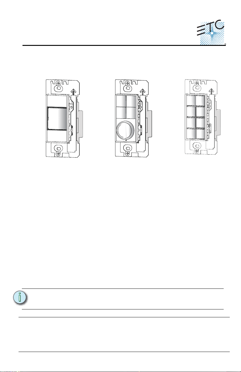
Stations are available in 1, 2, 4, 6, and 8 button assemblies, and a 4 button
with fader station. Station buttons are backlit by both blue and amber LEDs.
The 4 button with fader station knob is backlit with a blue LED.
Custom Configuration
This document guides you through the installation and local DIP switch setup
of the Echo Inspire station. For more detailed information about local
configuration options available for the Inspire station, reference the Echo
Inspire Station Programming Guide.
For information about the custom configuration options available for the
Inspire station using EchoAccess, reference the EchoAccess Mobile App
integrated help system. ETC’s user documentation is available from our
website www.etcconnect.com.
Note:
Corporate Headquarters Middleton, Wisconsin, USA Tel +608 831 4116 Service: (Americas) service@etcconnect.com
London, UK Tel +44 (0)20 8896 1000 Service: (UK) service@etceurope.com
Rome, IT Tel +39 (06) 32 111 683 Service: (UK) service@etceurope.com
Holzkirchen, DE Tel +49 (80 24) 47 00-0
Hong Kong Tel +852 2799 1220 Service: (Asia) service@etcasia.com
Web: www.etcconnect.com
Product information and specifications subject to change
7186M2140 Rev D Released 2016-02
Inspire Station Page 1 of 8 Electronic Theatre Controls, Inc.
To configure the Echo Inspire station using EchoAccess, the station
Function switch must be set to Custom.
Service: (DE) techserv-hoki@etcconnect.com
Copyright © 2016 ETC. All Rights Reserved.
. ETC intends this document to be provided in its entirety.
Page 2
ETC Installation Guide
Prepare for Installation
Inspire stations ship with station electronics, a decorator style wall plate,
termination kit, and a template of standard button labels. The station may be
installed into an industry standard back box (provided by others) or surface
mounted back box (sold separately and available from ETC).
Inspire stations connect to the EchoConnect station communication bus.
EchoConnect is a bidirectional protocol that uses one pair of wires (data+ and
data-) for both data and power. ETC recommends using Belden 8471 (or
approved equal) Class II wire.
The total combined length of an EchoConnect wire run (using Belden 8471, or
equal) may not exceed 1,640 feet (500m).
Inspire Station
Note:
Note:
All control wiring should be installed and terminated by a qualified
installer and should follow standard wiring installation practices.
Leave approximately 10 inches (254mm) of wiring in the back box for
connection and to allow slack for future service needs.
ETC requires that all stations be grounded. Pull an additional 14 AWG
(1.5mm
grounded metal conduit.
Environmental
• Indoor installation only - 0-50deg C, 5-95% non-condensing humidity
Installation
Installation should follow all local codes and standard electrical practices.
Note:
The back box should be installed plum and square for best results. Ensure that
the back box is clean and free of obstructions and that all wiring is installed
correctly.
NEC Class 2 product to be wired in accordance to NEC Article 725 and
local jurisdiction requirements.
2
) wire for grounding when control wires are not installed in
Inspire Station Page 2 of 8 Electronic Theatre Controls, Inc.
Page 3

ETC Installation Guide
Inspire stations ship with a termination kit for use with Belden 8471 (or
equivalent wire) and contains a power pigtail a ground wire pigtail, spacers,
and all required wire termination connectors for installation.
Inspire Station
Note:
When using Category5 (or equivalent) cable on the EchoConnect
communication bus, please note the following:
- Not all topologies are supported using Cat5; careful planning is
required to ensure the proper termination kits are available and the
wire is pulled appropriately.
- Cat5 wiring may be terminated using EchoConnect Cat5 Station
Termination Kit and must be installed using a bus topology. Refer to
the installation guide that is provided with the Cat5 Station
Termination Kit (7186A1207) for information to terminate Cat5
wiring.
Connect the Wiring
Step 1: Pull all required wiring (data+, data-) into the back box. As
needed, pull an additional ESD ground wire (required only
when the station is not installed in grounded metal conduit).
Step 2: Connect station ESD ground wire pigtail.
a: Strip 3/8” (9-10mm) of insulation from the ends of the
station ground wire pigtail, provided in the termination
kit, and the incoming ground wire.
b: Use one WAGO connector, provided in the termination
kit, to connect the station ESD ground pigtail and the
incoming ground. For stations using grounded metal
conduit, connect the ground pigtail to the metal backbox
ground location.
c: Install the ESD ground wire pigtail Faston connector to
the spade terminal on the station electronics.
Step 3: Terminate and connect EchoConnect wires. EchoConnect is
topology free, you may install the wires in any combination of
bus, star, loop, or home-run.
a: Strip 3/8” (9-10mm) from the ends of each power pigtail
wire, provided in the termination kit, and the installed
control wires.
b: Use one WAGO connector, provided in the termination
kit, to connect the power pigtail and the installed control
wires. Open the terminal levers on the WAGO connector
and insert the installed (typically black) Belden 8471 wire
Inspire Station Page 3 of 8 Electronic Theatre Controls, Inc.
Page 4

ETC Installation Guide
INSPIRE STATION
50mA @ 24VDC, CLASS 2, TYPE1
For use with Dimming and Relay Products
LISTED
INDUSTRIAL CONTROL EQUIPMENT
9Z49
ENERGY MGMT. EQUIP
Space
Switches
1 - Use Off
2 - Amber LED Disable
3 - Space Combine Mode
4 - Fade Time Override
5 - Zone Color Control
8 - Restore Defaults
rear of station
(4 button with
fader shown)
and the black lead from the power pigtail into the
terminals. Then close the levers.
c: Repeat for the installed (typically white) Belden 8471
power wires and the remaining white wire from the
power pigtail using a new WAGO connector.
d: Install the two pin connector from the power pigtail to
the mating receptacle on the station electronics.
Rotary and DIP Switches
Rotary and DIP switch settings are
accessible on the rear of the station.
Rotary Switch Assignments
Two rotary switches on the rear panel
of the station provide for space
assignment and station address
assignment. Each station must be set
to a unique station address for the
assigned space.
By default, these switches are set to
Space 1, Station Address 1. Station
commands are shared by all devices within an assigned space.
Inspire Station
DIP Switch Settings
DIP switches on the rear panel of the station provide for designation of “Off”
functionality, the ability to disable amber button LEDs, 4 button station space
combine controls, and the ability to restore the station to its factory defaults.
DIP Switch Settings
Switch # Use
1
2
3
Inspire Station Page 4 of 8 Electronic Theatre Controls, Inc.
Use Off - Provides “Use Off” functionality. When this is set to Off,
the “Off” function of the station is not provided.
Amber LED Disable - Provides the ability to disable use of the amber
LEDs. When this switch is set to On, amber button LEDs on the
station will be disabled. The default setting is Off, enabling amber
LEDs. (Amber LEDs is provided as the default so the station glows in
darkened spaces, allowing it to be easily located.)
Space Combine Mode - 4-button station only, changes the station
personality, enabling space combine.
Page 5

ETC Installation Guide
RECORD/
PROGRAM
MODE
Function switch
PRESET
CUSTOM
ZONE
front of
station
DIP Switch Settings [Continued]
Switch # Use
Fade Time Override (Disable) - Applies a 0 second fade time to all
4
5
6 Future development
7 Future development
8
station actions for non-dim switched mode behavior (when dimming
features are not wanted).
Zone Color Control - 4-button with fader station only, changes the
Zone mode (function selection switch) of the station into Color
Control mode.
Restore to Defaults at boot. Setting this DIP switch, then cycling
power to the station restores the station to factory defaults
Inspire Station
Note:
When the station Function switch is set to Custom, only DIP switch
number 8 applies. All other DIP switch settings are ignored. Reference
the Echo Inspire Station Programming Guide (available for download
from the ETC website www.etcconnect.com for details on use of the
Function switch.
Station Configuration
The Inspire station has on-board switch and button settings that are available
from the front of the station when it is installed and the cover is removed.
Reference the Echo Inspire Station Programming Guide for information about
local settings on your Inspire Station, including configuration, program and
record mode, and station functionality. ETC’s user documentation is available
for free download from our website www.etcconnect.com.
Reference the EchoAccess Mobile App integrated help system for details about
custom configuration using the EchoAccess.
Inspire Station Page 5 of 8 Electronic Theatre Controls, Inc.
Page 6

ETC Installation Guide
Step 1: Remove the bezel from the station
electronics.
• Each corner of the bezel is
provided with a notch to
assist with bezel removal. Use
your thumbnail to lift a corner
free, then gently remove the
bezel from the station.
Step 2: Remove the button lens.
• Using the pads of your
thumbs, press on the lens and
slide the lens either left or
right, toward the button
hinge points.
Step 3: Once the lens is removed, remove
the existing legend and replace it
with another standard legend, as
provided with this station, or insert
a custom legend.
P
r
e
s
e
t
7
Step 4: Replace the lens onto the
button by aligning the grooves
of the lens to the button, then
sliding the lens in place starting
at the hinge. Slide the lens until
it covers the entire button and
clicks into place.
Install Button Legends
Inspire stations ship with standard button legends installed beneath a clear
lens. An additional sheet of standard button legends are provided for field
installation as needed.
Inspire Station
Note:
Customize and print your own button legends on standard
transparency. Download the button legend template provided on the
ETC website www.etcconnect.com.
Each button can have a legend, installed beneath the button lens. To remove,
install, or replace a button legend you must first remove the bezel and button
lens from the station electronics.
Inspire Station Page 6 of 8 Electronic Theatre Controls, Inc.
Page 7

ETC Installation Guide
Inspire Station
Step 5: Replace the bezel to the station electronics when all legends
and lenses are in place.
Install the Station into the Back Box
Receptacle spacers are provided to help align the station and cover flush
against the wall in flush mount application. The spacers are not required when
installing the station into a surface mount back box.
Step 1: Insert the station electronics and wiring into the back box. To
install multiple stations (multi-gang), insert the station
electronics into the back box from the right to the left side for
the best alignment and fit. The alignment bracket will slightly
overlap the station to the right when properly installed.
Step 2: Use spacers as needed to provide a flush mounted station.
a: Fold the spacer in a zig-zag fashion and press the stack
together to achieve the thickness needed to fill the gap
between the station, wall surface, and the back box.
b: Cut off and discard the excess.
c: Place the stack between the station electronics and the
flush mounted back box.
Inspire Station Page 7 of 8 Electronic Theatre Controls, Inc.
Page 8

ETC Installation Guide
Step 1: Align the top of the wall plate to the
station and angle the bottom
approximately 20 degrees.
Step 2: Hook the top of the wall plate to the
tabs located on the station electronics
assembly. To ensure the wall plate is
hooked properly on the top hook,
wiggle it slightly side to side.
Step 3: Swing the bottom of the wall plate
down until the magnets engage.
Step 4: If the wall plate does not fully attach
automatically, wiggle the bottom of the
plate until all of the magnets are seated
properly to the station and the plate is
secure.
Step 3: Secure each station electronics in place using the two screws
provided. If using spacers, insert the screws through the
spacers as well.
Inspire Station
CAUTION:
To improve successful station and wall plate installation, do not
over tighten the screws. If screws are over tightened, button
activation can be negatively impacted.
Install the Wall Plate
The wall plate is secured to the station with built-in magnets.
Note:
Inspire Station Page 8 of 8 Electronic Theatre Controls, Inc.
When installing a multi-gang wall plate and the stations are
misaligned in the back box, the wall plate will not attach properly.
Loosen the screws that secure the station to the backbox, adjust each
station to improve the alignment, secure the screws, then retry wall
plate installation.
 Loading...