

Page 1
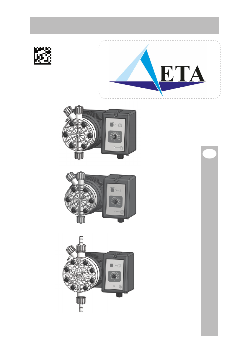
T - TA - T AC
T
TA
T AC
SOLENOID DRIVEN METERING PUMPS
WITH DIAPHRAGM
EN
OPERATING MANUAL
Page 2

This operating instructions contains safety information that if ignored can endanger life or result
in serious injury.
Read these instructions carefully before use and keep them for future reference. The original
instruction is in Italian. All non-Italian instructions are translations of the original instruction.
Information and specifications on this manual could be uncorrect or could have printing errors.
Specifications are subject to change without notice.
Version: R2-12-13
NORME CE
EC RULES (STANDARD EC)
NORMAS DE LA CE
Direttiva Basso Voltaggio
Low Voltage Directive
Directiva de baja tensión
Direttiva EMC Compatibilità Elettromagnetica
EMC electromagnetic compatibility directive
EMC directiva de compatibilidad electromagnética
Norme armonizzate europee nell’ambito della direttiva
European harmonized standards underdirective
Las normas europeas armonizadas conforme a la directiva
2006/95/CE
⎬
2004/108/CE
⎬
2006/42/CE
⎬
ICON
2
T metering pump is tested and certified by WQA to NSF/ANSI 50 and 61 for materials safety.
GENERAL SAFETY GUIDELINES
Operating, installing, or maintaining the unit in any way that is not covered in this manual could
cause death, serious personal injury, or damage to the equipment.
This manual use the following safety message icon:
Danger!
Indicates a hazardous situation which, if not avoided, will result in death or serious injury.
Warning!
Indicates a hazardous situation which, if not avoided, could result in death or serious injury.
Important - A practice not related to personal injury or additional information.
Cross reference - An instance which refers to related information elsewhere in the same
⎘
document
Page 3

PURPOSE OF USE AND
SAFETY
METERING PUMP IS INTENDED FOR CHEMICAL DOSING AND DRINKING WATER
TREATMENT.
Do not use in explosive area (EX).
Do not use with flammable chemicals.
Do not use with radioactive chemicals.
Use after a proper installation.
Use the pump in accordance with the data and specifications printed on the label.
Do not modify or use in a manner inconsistent with the provisions of the operating manual.
Keep the pump protected from sun and water. Avoid water splashes.
In emergencies the pump should be switched off immediately. Disconnect the power
cable from the power supply.
When using pump with aggressive chemicals observe the regulations concerning the
transport and storage of aggressive fluids.
When installing always observe national regulations.
Manufacturer is not liable for any unauthorized use or misuse of this product that may
cause injury, damage to persons or materials.
Pump must be accessible at all times for both operating and servicing. Access must
not be obstructed in any way.
Feeder should be interlocked with a no-flow protection device.
Pump and accessories must be serviced and repaired by qualified and authorized
personnel only.
Before any operation:
• always read chemical Material Safety Data Sheet (MSDS);
• always wear protective clothing;
• always discharge the liquid end before servicing the pump.
• empty and rinse the liquid end before work on a pump which has been used with
hazardous or unknown chemicals.
This equipment requires regular maintenance to ensure potability requirements of the
water and maintenance of improvements as declared by the manufaturer.
3
Page 4
ENVIRONMENTAL
SAFETY
Work area
Always keep the pump area clean to avoid and/or discover emissions.
Recycling guidelines
EWC code: 16 02 14
Always recycle according to these guidelines:
1. If the unit or parts are accepted by an authorized recycling company, then follow local recycling
laws and regulations.
2. If the unit or parts are not accepted by an authorized recycling company, then return them to
the nearest representative.
Waste and emissions regulations
Observe these safety regulations regarding waste and emissions:
• Dispose appropriately of all waste.
• Handle and dispose of the dosed chemical in compliance with applicable environmental
regulations.
• Clean up all spills in accordance with safety and environmental procedures.
• Report all environmental emissions to the appropriate authorities.
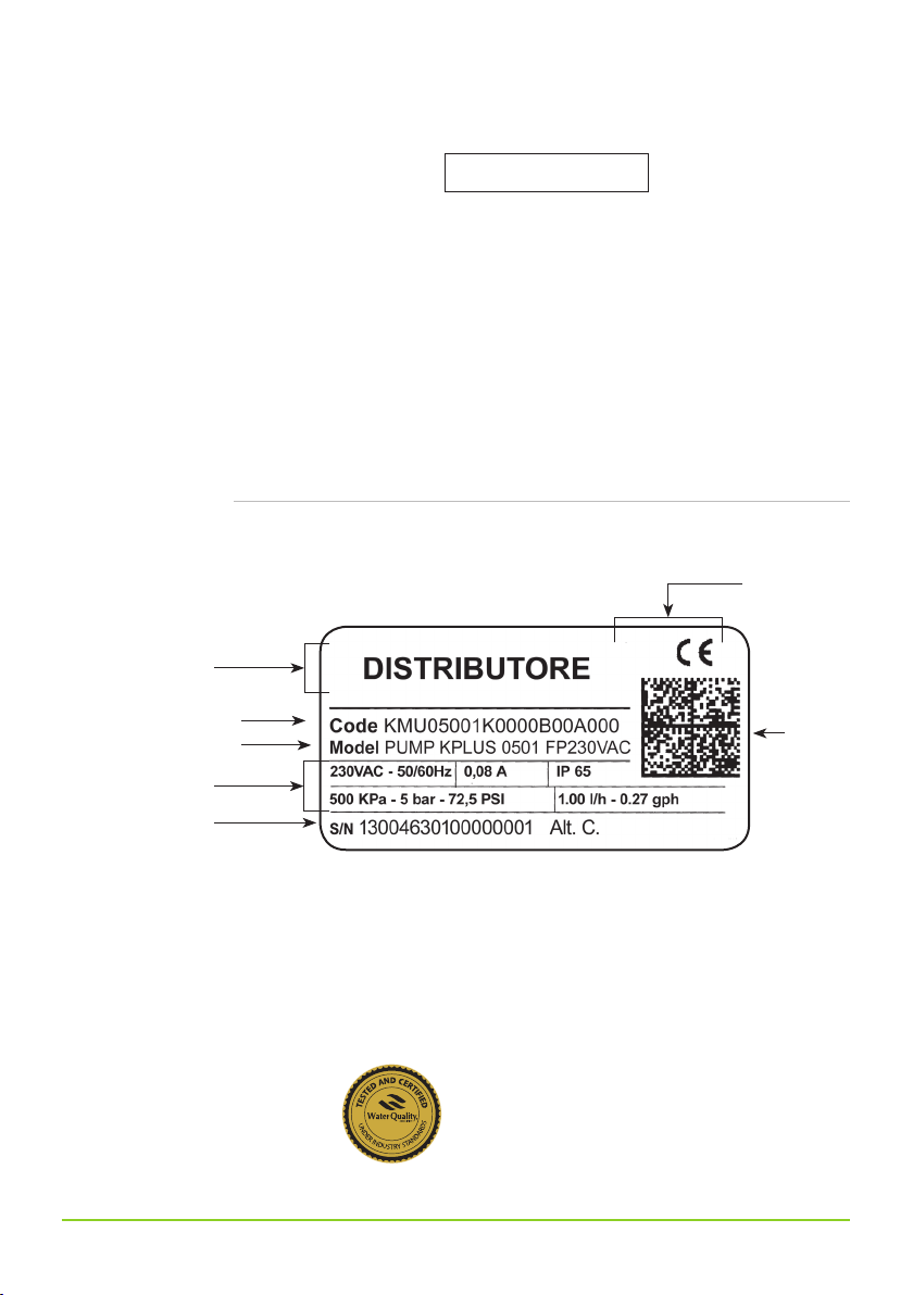
LABELS
Distributor
CODE: pump code
MODEL: pump model
PUMP’S DATA
S/N: serial number
Spare parts
Fig. 1. Product label.
CE conformity
UL conformity
(if any)
Data
matrix
For spare parts orders or any other communication, refer to product label.
Code (CODE) and serial number (S / N) uniquely identify the pump.
Fig. 2. WQA label.
THIS METERING PUMP IS TESTED AND CERTIFIED
BY WQA TO NSF/ANSI 50 AND 61 FOR MATERIALS
SAFETY.
4
Page 5

Transportation and
storage
A not suitable transportation or storage can cause damages.
Use origianal box to pack the pump.
Observe storage conditions also for transportation.
Although packed, always protect the unit against humidity and the action of
chemicals.
Before return the dosing pump to the manufacturer Repair service, drain the chemical
from pump head and rinse it. Refer to ⎘ Shutdown procedure.
Fill the PRODUCT SERVICE REPAIR FORM and send it with the dosing pump.
Repair service is not accepted if PRODUCT SERVICE REPAIR FORM is missing.
DO NOT TRASH PACKAGING. USE IT TO RETURN THE PUMP.
Transportation and storage temperature ..... 10 ÷ 50°C (32 ÷ 122°F)
Umidity ...................................................... 95% relative humidity (not condensed)
5
Page 6
1. Introduction
Introduction:
Metering Pumps “T” Series are the ideal solution for low / middle dosing of chemicals. All
control and setup parameters are available through knobs and a visual system (led).
Metering Pumps “T” Series have got an On/Off digital switch for ensure dosing activity
(available only for some models).
NSF/ANSI 61
T metering pumps with manual venting PVDF pump head
TA metering pumps with self venting PVDF pump head
NSF/ANSI 61
T AC metering pumps with manual venting pump head and compressed air + 230VAC power supply
Pump’s capacity
Flow rate is determined by the stroke speed.
The stroke speed is adjustable from 0 to 100% using the stroke adjustment knob.
However dosing accuracy is guarantee within an adjustment range from 30% to 100%.
The led on the frontal panel shows the activity status of the pump.
Models:
SERIES MOD. DESCRIPTION
T - TA - TAC CO Constant pump with stroke speed (frequency) adjustment
CL Constant pump with level control, stroke speed (frequency) adjustment
Constant-proportional pump driven by external digital signal with level control: to each external pulse
IS
correspond one pump stroke
Constant-proportional pump driven by external digital signal with pulse divider mode (ratio 1 to 1000) and
PV
level control
Constant-proportional pump driven by external digital signal, level control , with pulse divider mode (ratio 1
PVM
to 100) and multiplier mode (ratio 1 to 10)
Constant-proportional pump driven by current signal (0/4mA = 0 pulses; 20mA = max pulses) and level
IC
control
TE (0”÷60”) timered pump with external digital signal and level control
Capacity T
Pressure Flow
bar l/h
20 05
05 15
04 20
03 30
01 50
00 100
Capacity TA
Pressure Flow
bar l/h
20 3,2
05 10
04 13
Capacity T AC
Pressure Flow
bar l/h
10 50
05 150
00 230
6
Page 7
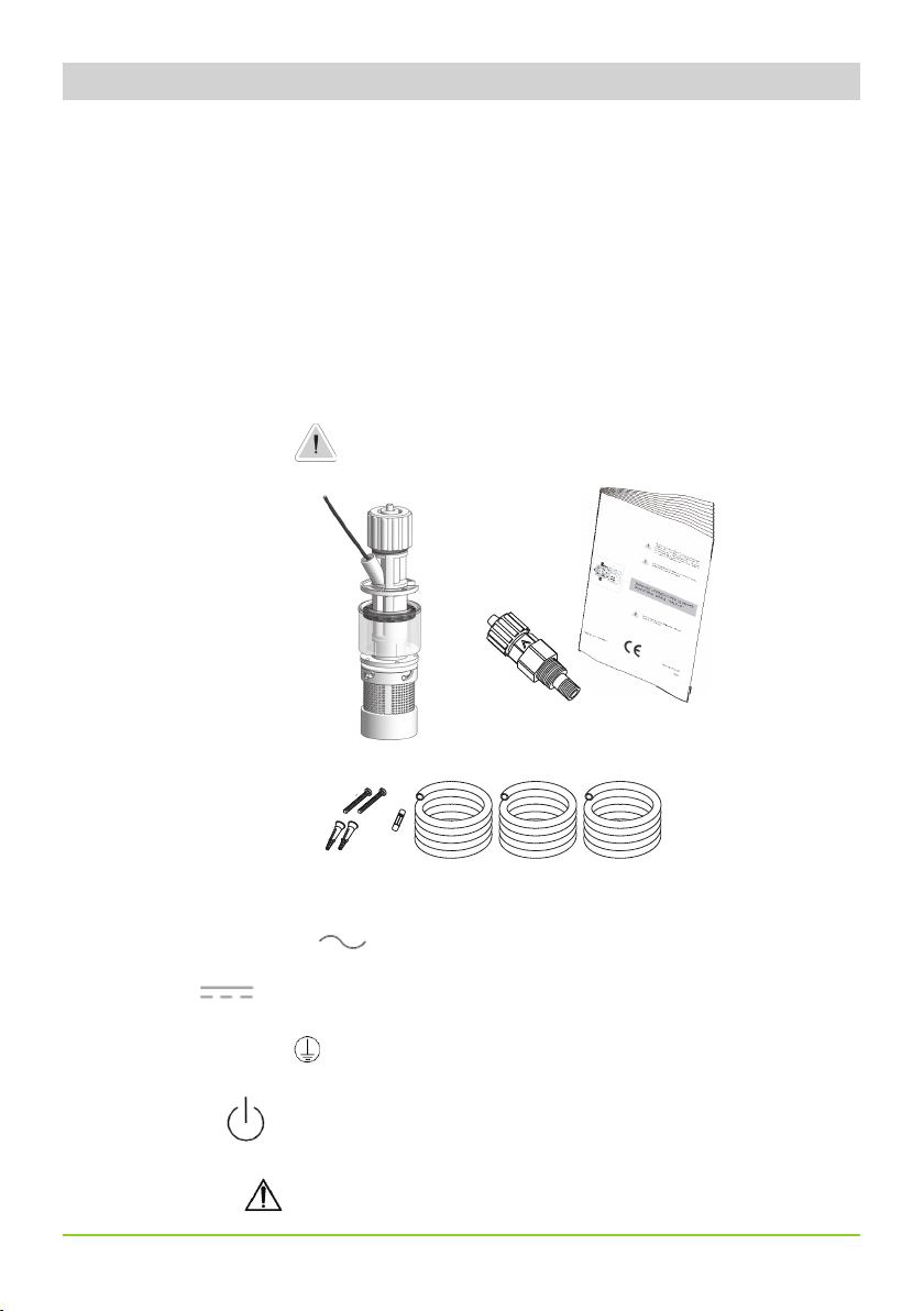
2. Unpacking
Included into package:
n.2 Dibbles ø6
n.2 Self tapping screws 4,5 x 40
n.1 Delayed fuse 5 X 20
n.1 Level probe with axial foot filter (PVDF)
n.1 Injection valve
m 2 Delivery pipe (PVDF)
m 2 Suction pipe (transparent PVC)
m 2 Venting hose (transparent PVC)
n.1 This installation manual
* If hose is 6x8 there is only a 4meters long hose.
Cut to obtain suction and delivery hoses.
Remove the contents from the box.
PLEASE DO NOT TRASH PACKAGING.
IT CAN BE USED TO RETURN THE PUMP.
Legend:
a. Alternating Current;
b. DC,
c. Protective Earth;
d. Standby;
e. Warning -
7
Page 8

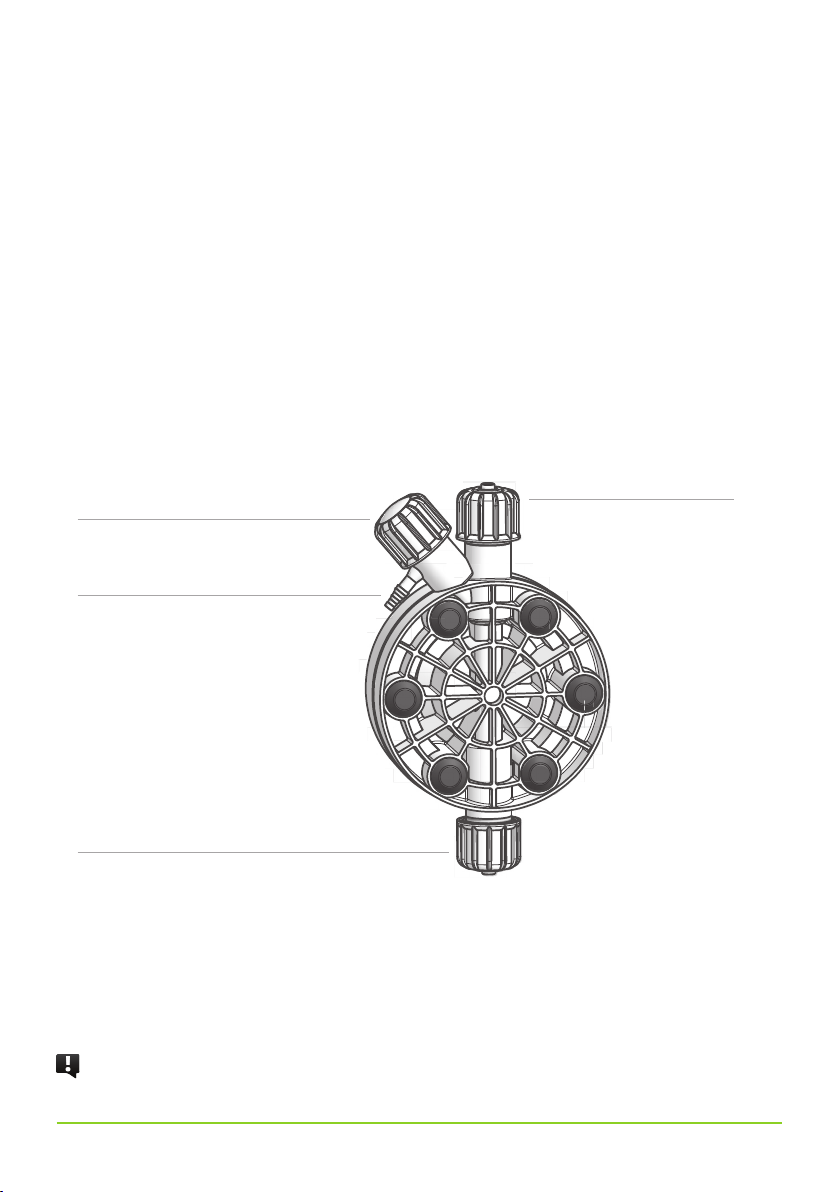
To delivery hose
Venting knob
To venting hose
Pump head
To suction hose
External signal input
Compressed air input (for T AC model only)
3. Pump’s description
Power supply
Level probe input
N.B. TA series (self-venting metering pumps) is described on p. 14.
8
Page 9

4. Before to Install warnings
Pump’s installation and operativity is made in 4 main steps:
Pump’s installation
Hydraulic Installation (hoses, level probe, injection valve)
Electrical Installation (main power connection, priming)
Programming the pump.
Before to start, please read carefully the following safety information.
Protective clothes
Wear always protective clothes as masks, gloves, safety glasses, ear plugs or ear
muffs, and further security devices during ALL installation procedure and while
handling chemicals.
Installation location
Pump must be installed in a safety place and fixed to the table / wall to
avoid vibration problems!
Pump must be installed in a easy accessible place!
Pump must be installed in vertical position!
Avoid water splashes and direct sun!
Hoses and Valves
Suction and delivery hoses must be installed in vertical position!
All hoses connections must be performed using only hands’ force!
No tongs required!
Delivery hose must be firmly fixed to avoid suddenly movements
that could damage near objects!
Suction hose must be shorter as possible and installed in vertical
position to avoid air bubbles suction!
Use only hoses compatibles with product to dose! See chemical
compatibility table. If dosing product is not listed please
consult full compatibility table or contact chemical’s manufacturer!
Feeder should be interlocked with a no-flow protection device to automatically shut-off the
pumps when there is no flow!
Adequate measures shall be taken to prevent cross connection of chemicals!
Chemical feeding must be stopped during backwash cycles and periods of noflow as these conditions may introduce the potential for chemical overdosing. Not doing so may result in elevated
chemical concentrations and hazerdous gas introduction into the pool or spa.
9
Page 10
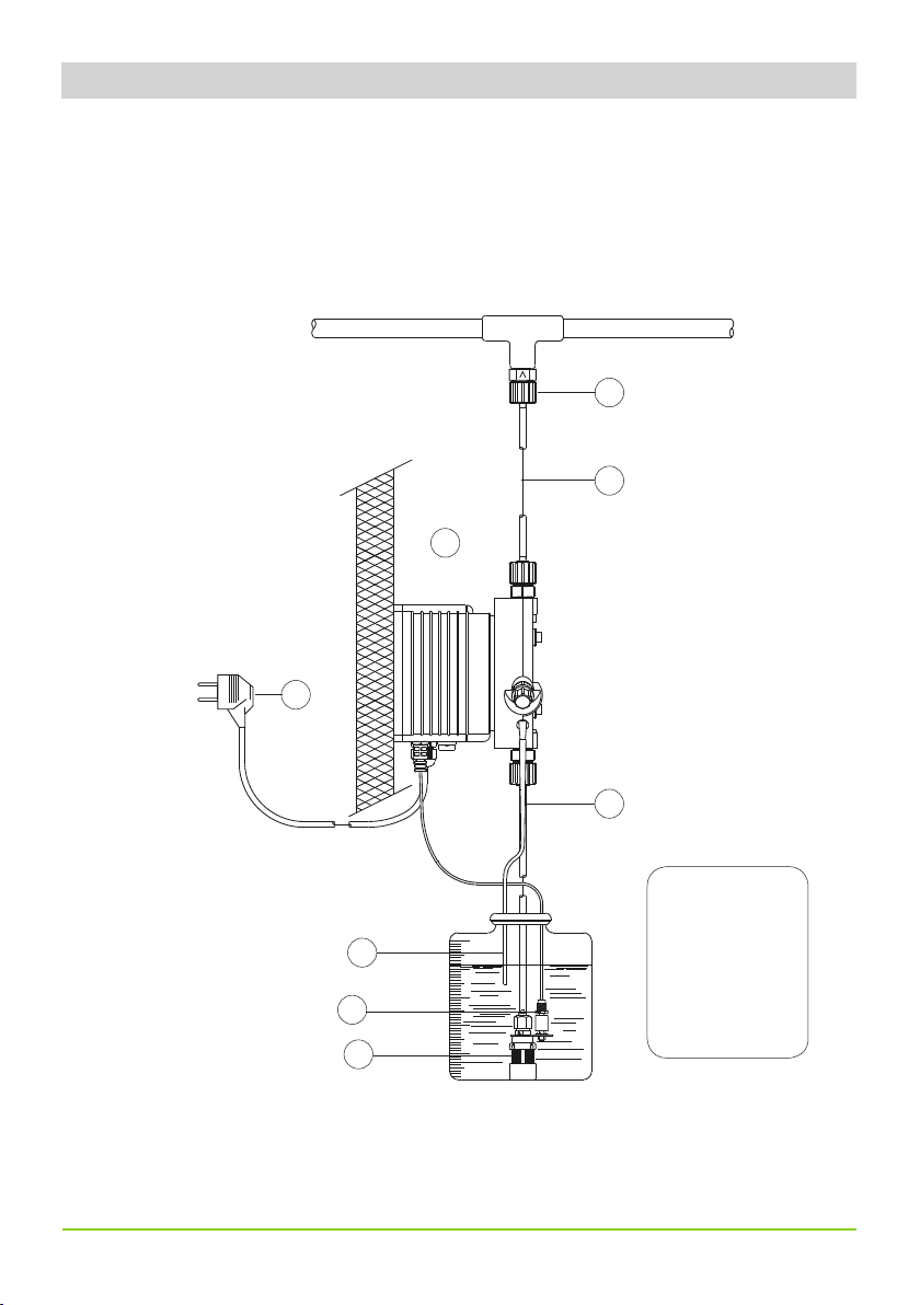
5. Installation draw
Pump must be installed in a wall support at a maximum height (from tank’s bottom) of 1,5 meters.
4
3
1
8
10
2
1 - Dosing Pump
2 - Suction Hose
3 - Delivery Hose
5
6
7
4 - Injection Valve
5 - Air discharge
6 - Level Probe
7 - Foot Filter
8 - Power Cable
Page 11
6. Hydraulic installation
Hydraulic connections are:
Suction Hose with level probe and foot filter
Delivery Hose with injection valve
Venting hose
6.1 Suction Hose.
Completely unscrew tightening nut from pump’s head and remove assembling
components: tightening nut, holding ring and pipe holder.
Assembly as shown in fig. (A). Insert hose into pipe holder until it reaches the bottom.
Lock hose on pump’s head by screwing down the tightening nut.
Use only hands to do it!
Connect other side of the hose to the foot filter using the same procedure.
Suction Hose
Tightening Nut
Holding Ring
Pipe Holder
O-ring
Valve
fig. (A)
11
Page 12

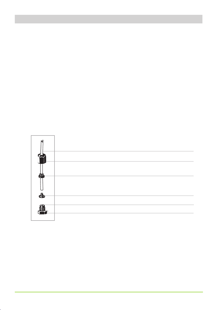
6.2 Assembling foot filter with level probe.
Level probe must be assembled with foot filter using the provided kit.
Foot valve is made to be installed into tank’s bottom without sediments priming problem.
INSERT PROBE
WITH N.O. CONTACT
UNTIL TO HEAR
STEP 5
STEP 3
A CLICK
STEP 4
INSERT RING AS SHOWN
STEP 2
INSERT FLOATER
STEP 1
INSERT RING AS SHOWN
Connect BNC from level probe into pump’s level input (front side of the pump).
Put level probe assembled with foot filter into tank’s bottom.
Warning: If there is a mixer installed into tank, install a suction lance
instead of level probe / foot filter.
6.3 Delivery Hose.
Completely unscrew tightening nut from pump’s head and remove assembling
components: tightening nut, holding ring and pipe holder.
Assembly as shown in fig. (A). Insert hose into pipe holder until it reaches the bottom.
Lock hose on pump’s head by screwing down the tightening nut.
Use only hands to do it!
Connect other side of the hose to the injection valve using the same procedure.
12
Page 13
6.4 Injection Valve.
1
2
3
4
5
Injection valve must be installed on plant from water’s input.
Injection valve will open at pressure greater than 0,3bar.
6.5 Manual venting hose.
Insert one side of venting hose into manual venting connector as shown in fig (C).
Insert other side of venting hose into product’s tank.
During priming procedure product exceeding will flow into tank.
to delivery hose
Venting knob
to manual venting hose
to suction hose
For priming procedure see
PRIMING.
fig (C)
it’s allowed to lightly bend the venting hose.
During calibration procedure (“TEST”) insert venting hose into BECKER test-tube.
13
Page 14
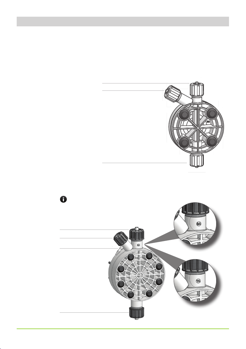
7. Self-Venting pump head installation
2
3
4
5
6
Self-venting pump head must be used when using chemicals that produce gas (i.e. hydrogen peroxide, ammonium, sodium
hypoclorite at particular conditions).
Refer to fig. 3-4 for delivery and Self venting hose.
Hoses assembling procedures are the same described before.
Fig. 3. Self-venting models pump head: LA, MA, NA (TA).
To Self venting hose
To delivery hose
To suction hose
Fig. 4. Self-venting models pump head: SA, TA (TA).
ON “SA” AND “TA” MODELS THERE IS A RED THREADING NUT
To delivery hose
RED THREADING NUT
To Self venting hose
To suction hose
14
Page 15
8. Electrical Installation
All electrical connections must be performed by AUTHORIZED AND QUALIFIED personnel only.
Before to proceed, please, verify the following steps:
- verify that pump’s label values are compatible with main power supply.
- pump must be connected to a plant with a differential switch (0,03A
sensitivity) if there isn’t a good ground.
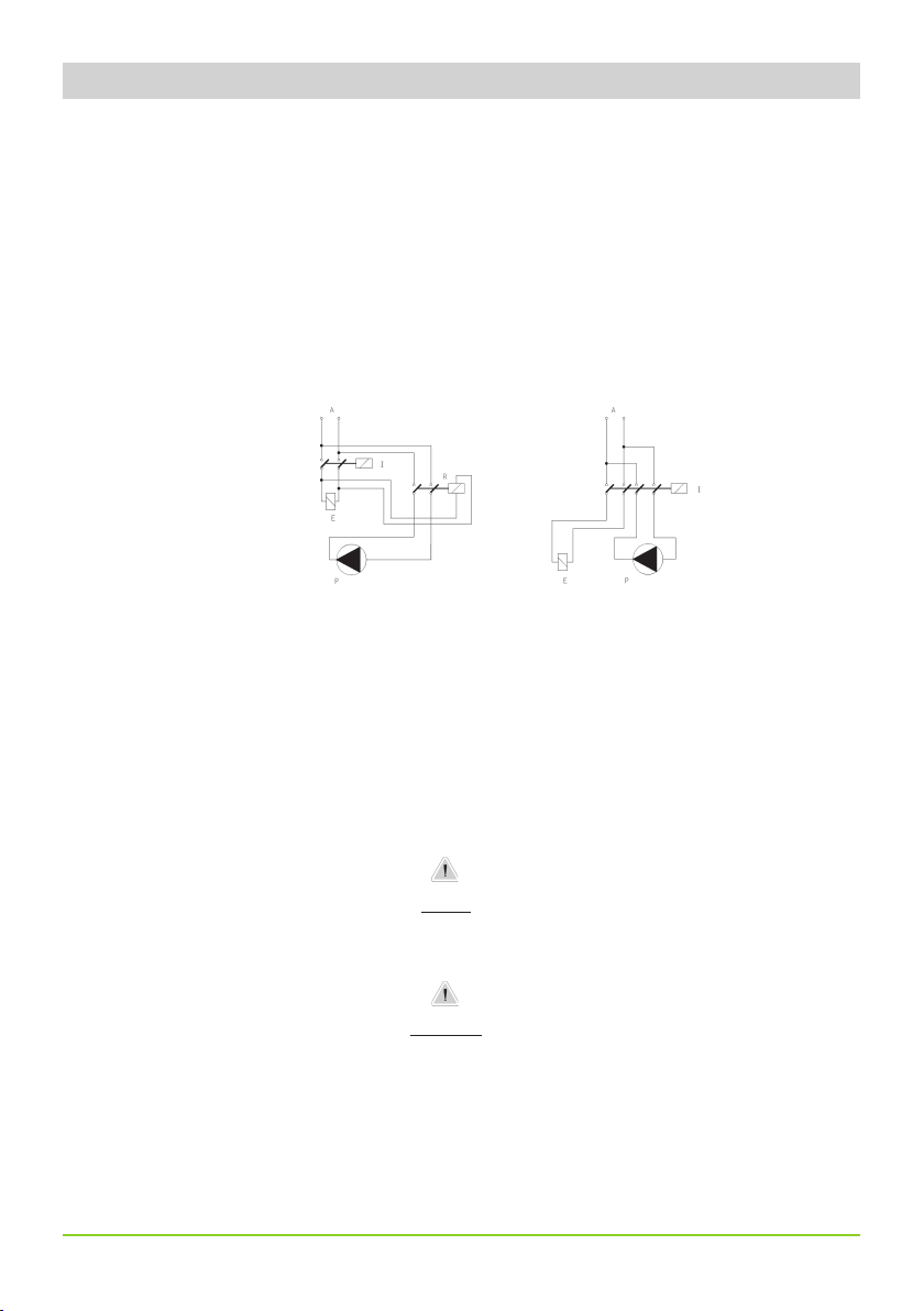
- to avoid damages to the pump do not install it in parallel with heavy
inductance load (for example: engines). A relay switch must be used. See
below picture.
P - Dosing Pump
R - Relay
I - Switch or safety device
E - Electrovalve or inductance load
A - Main Power
IF EQUIPMENT IS SUPPLIED WITH A PLUG:
If an appliance coupler or separable plug is used as the disconnecting device, it shall be readily identifiable and easily reached by the operator. For single-phase portable equipment, a
plug on a cord of length not greater than 3m is considered to be easily reached.
IF EQUIPMENT IS NOT SUPPLIED WITH A PLUG:
a) a switch or circuit-breaker shall be included in the building installation
b) it shall be in close proximity to the equipment and within easy reach of the operator
c) it shall be marked as the disconnetting device for the equipment
WARNING
WARNING
15
Page 16

Once verified previous steps proceed as follows:
- check that “BNC” of level probe has been connected as described in “Hydraulic
Installation” chapter.
- connect “BNC” and external signal to pump’s “INPUT” connectors.
2
1
Level Probe Input available on: TIC, TIS, TPV, TPVM, TCL, TTE
External Signal Input available on: TIC, TIS, TPV, TPVM, TTE
Level Probe Input
External Signal Input
1
2
16
Page 17

8. Level alarm
LEVEL ALARM
CL, IS, IC, PV, TE and PVM type pump are provided with a liquid level alarm to indicate product tank is empty. The level probe
is connected to the right BNC plug on pump’s bottom panel. The level probe is made of a N.O. reed contact (10VA, 1A max.,
230Vac max.) closed by a floating magnet housed in a (PP) plastic box. When the product level goes below the minimum the
magnet closes the reed contact. The pump stops and the red LED on pump’s front panel indicates the alarm status.
PUMP TYPES
Pumps mod. “TCL” (12-24 Vac/Vdc), “TIC”, “TIS”, “TPV” and “TPVM” are equipped with a bicolour led.
Led on, red colour: low level product alarm. Check product’s tank and restore the level.
Led on, blinking green colour: pump normal operating mode.
Led on, blinking green colour (one second on, one second off): power supply out of range. Check pump’s label and check the
main power.
17
Page 18

9. Models
TCO MODEL
Constant dosing pump with stroke speed adjustment between 0 and 100% of indicated capacity (see label on pump type). The
% marked knob sets the pump capacity, changing linearly the magnet stroke number per minute. It is strongly suggested to not
operate the pump in the range from 0 to 10%, since there is not a linear correlation with the pump stroke speed in that range.
This pump is specially designed for constant dosing rates. TCO pump can be ON/OFF driven by a LPH or a LCD instrument. To
set 2.5 l/h against 5 bar on a TCO 0505 the % marked knob should be set to 50%.
TCO has a divider (x- 0,1) to reduce by ten times the pump capacity by dividing the pump stroke speed.
How to enable “divider mode”:
- set the pump into OFF* mode;
- keeping pressed the on/off button, wait 3 flashes from the status led. The pump will start the dosing activity with the stroke
speed reduced ten times than the value set on stroke lenght knob.
To disable the “divider mode”, power OFF the pump. Keeping pressed the on/off button, wait 3 flashes of the status led.
ON/OFF BUTTON
STROKE LENGHT KNOB
ON/OFF
30
20
10
0
50
40
60
70
80
90
100
%
LED
The led on the frontal panel shows the pump’s operating status through 5 flashing:
GCO
LED ACTIVITY
It flashes 3 times per second
PUMP’S STATUS
the pump is powered with a power supply lower than the label
It flashes 2 times per second the pump is powered with a power supply higher than the label
It flashes 1 time every 2 seconds
led ON, it switches off when pump
strokes
led ON, it switches off 1 time every 2
seconds
the pump is in pause (OFF) and it is powered (OFF* mode)
the pump is active and functioning (ON)
the pump is working into DIVIDE mode
STATUS LED
18
Page 19

TCL MODEL
Cod. 090.1255.0-GCL-PULSANTE-grigio 157/blu
Constant dosing pump with level alarm, provided with a floating magnetic sensor probe.
A red led indicates that the pump stopped dosing because the product tank is empty.
This pump has stroke speed adjustment between 0 and 100% of indicated capacity (see label on pump type).
The % marked knob sets the pump capacity, changing linearly the magnet stroke number per minute. It is strongly suggested to
not operate the pump in the range from 0 to 10%, since there is not a linear correlation with the pump stroke speed in that range.
TCL has a divider (x- 0,1) to reduce by ten times the pump capacity by dividing the pump stroke speed.
How to enable “divider mode”:
- set the pump into OFF* mode;
- keeping pressed the on/off button, wait 3 flashes from the status led. The pump will start the dosing activity with the stroke
speed reduced ten times than the value set on stroke lenght knob.
To disable the “divider mode”, power OFF the pump. Keeping pressed the on/off button, wait 3 flashes of the status led.
ON/OFF button
Stroke length
adjustment knob
ON/OFF
30
20
10
0
40
GCL
50
60
70
80
90
100
%
LED
The led on the frontal panel shows the pump’s operating status through 5 flashing:
LED ACTIVITY
It flashes 3 times per second
PUMP’S STATUS
the pump is powered with a power supply lower than the label
It flashes 2 times per second the pump is powered with a power supply higher than the label
It flashes 1 time every 2 seconds
led ON, it switches off when pump
strokes
led ON, it switches off 1 time every 2
seconds
the pump is in pause (OFF) and it is powered (OFF* mode)
the pump is active and functioning (ON)
the pump is working into DIVIDE mode
status led
level alarm led
19
Page 20

TIC MODEL
Proportional/constant pump driven by current signal.
Setting the switch on the constant position the pump has stroke speed adjustment between 0 and 100% of indicated capacity
(see label on pump type). The % marked knob sets the pump capacity, changing linearly the magnet stroke number per minute.
It is strongly suggested to not operate the pump in the range from 0 to 10%, since there is not a linear correlation with the
pump stroke speed in that range.
Setting the switch on the proportional position the pump capacity is set proportionally to a given analog current signal; a given
signal linear change will be followed by a linear change of capacity.
The current signal accepted range is 0÷20 mA (it can be changed upon demand). The maximum pump capacity requested by
the maximum input signal is set by the % marked knob. The IC pump can be driven by any electronic device (such as pH-meter,
redox-meter, etc) that gives an analog current signal output. This signal must be applied to the bipolar cable provided with the
pump, already internal connected, taking care of connections:
ON/OFF button
- red wire : positive (+)
- black wire : negative (-)
Stroke length adjustment knob
20
proportional
constant
level alarm led
Page 21

TIS
Proportional/constant pump driven by a digital signal. Setting the switch on the constant
features and adjustments of the CL pump. Setting the switch on the proportional
pulse correspond a magnet stroke. When proportional position is set, the % marked knob does NOT affect the pump capacity.
IS proportional dosing pump can be driven by any external device (PCs, PLCs, etc) that produce a digital signal. The digital signal
(N.O. contact) must be applied to the cable provided with the pump, already internal connected. If the digital signal is produced
by an “Open Collector” transistor take care of connections:
- red wire : positive (+)
- black wire : negative (-)
On/Off
Stroke length adjustment knob
position, the pump has the same
position, to each external voltage free
proportional
constant
level alarm led
21
Page 22

TPV
Proportional/constant pump driven by a water meter digital signal. Setting the switch on the constant
position, the pump
has the same features and adjustments of the CL pump. It is furthermore possible to divide the maximum magnet strokes
per minute by 1, 10 and 100 using the switch on the front panel. Setting the switch on the proportional position, to each
external pulse correspond one pump stroke. This pump can be driven by a CTFI or CWFI series water meters. This pump can
also be driven by a digital signal coming from a voltage free contact. Driving signal is applied on the BNC plug on the left of
the bottom pump cover. Dividing factor (N) value is obtained multiplying the indicated value on the adjustment knob by the
multiplying switch (x1, x10, x100) value.
Capacity definition for “TPV” pump
Given the water m3 to be treated and the product amount to dose in p.p.m., the minimum pump capacity to be used can be
obtained with the following formula:
ppm x K x m
3
——————————————— = l/h
1000
l/h - minimum pump capacity required
ppm - product amount to dose in p.p.m. (gr/m
k - dosed product dilution factor (pure chemical k=1)
3
- maximum capacity of the system to be treated in m3 /h.
m
3
)
Dividing factor (N) to be set on the adjustment knob is given by the following formula:
imp/l x cc
( ———————————— ) x 1000 = N
ppm x K
N - is the number the external pulses are divided by to be set on the adjustment knob
cc - pump’s single stroke dosing quantity (in cc). Refer to following table
imp/l- pulse per liter given by the water meter
k - dosed product dilution factor (pure chemical k=1)
ppm* - product amount to dose in p.p.m. (gr/m
* 10.000 ppm equals to 1%
3
)
22
Page 23

If the dividing factor (N), obtained with the above formula, is <1, a pump with higher single stroke dosing quantity is required
or the water meter needs to be changed with one that gives higher number of pulses per liter. In some application this issue
can be solved reducing the dosed product dilution factor. If dosed amount is higher than the needed one, the set dividing
factor (N) can be increased.
On/Off
selector
proportional
Stroke length adjustment knob
constant
level alarm led
23
Page 24

TPVM
Proportional/constant pump driven by a water meter digital signal. Setting the switch on the constant
has the same features and adjustments of the CL pump. It is furthermore possible to divide the maximum magnet strokes per
minute by 1 (÷1), 10 (÷10) and 100 (÷100) using the switch on the front panel. The electronic capacity adjustment sets the
injection per minute. Setting the selector on the proportional position and the selector on “multiplier” (X1), the pump gives
a stroke each 10 external pulses sent. Setting the selector on “divider” (÷1 or ÷10), the pump gives at maximum a stroke each
external pulse sent and at minimum a stroke each 100 pulses sent. This pump can be driven by a CTFI or CWFI series water
meters. This pump can also be driven by a digital signal coming from a voltage free contact. Driving signal is applied on the
BNC plug on the left of the bottom pump cover.
On/Off
Stroke length adjustment knob
position, the pump
selector
proportional
constant
level alarm led
24
Page 25

TTE
Timered/constant dosing pump. Setting the switch on the constant
position, the pump has the same features and adjustments
of the CL pump. Setting the switch on timered , the pump starts working when an external pulse is provided. Working
active time for each external pulse is set on the adjustment knob in the range between 0 and 60 seconds (different time are
available upon demand). The capacity can be also changed adjusting the stroke per minute, operating the % marked knob,
at the same time. The double parameter adjustment (strokes and time) allows the use of this pump in high capacity systems,
where the pulses are not enough to drive a PV type pump. TE pump is provided of a coaxial cable (RG58) with BNC plug to
connect the command signal.
Use following formula to evaluate the knob adjustment:
3600
—————————— = sec.
imp/h
imp/h - water meter output pulse per hour
sec - time in seconds to be set on time knob
Maximum tag capacity can be decreased 10 or 100 times in the “G” pumps using the 1/10/100 switch (where available).
In that case the % marked knob will work on the maximum set capacity.
ON/OFF button
Stroke length
adjustment knob
25
Timer
timered
constant
level alarm led
Page 26

10. Priming
PRIMING
On the pump head there is a Self venting hose (left side).
To prime the pump without touching the chemical proceed as follow:
1. connect the transparent hose to the Self venting hose and insert its end into the chemical tank;
2. open the discharge valve turning the knob;
3. turn on the pump and set the stroke lenght adjustment knob on 100% and the stroke speed (frequency) adjustment knob
on 100% (between 50% and 70% for high viscosity chemicals).
4. All air inside the pump will exit through the discharge valve. When the chemical begin to flow into Self venting hose, close
immediately the venting knob.
If the chemical is particularly dense, to facilitate the priming:
1. turn on the pump and open the discharge valve;
2. insert a 20cc syringe into the Self venting hose and suck;
3. when the syringe is near to full, close the discharge valve.
26
Page 27

11. Troubleshooting
Problem
Pump doesn’t turn on.
Pump is not dosing and
solenoid is operating.
Pump is not dosing and solenoid
isn’t operating or slightly
operating.
Possible Cause
Pump isn’t powered. Connect it to main supply.
Pump’s protection fuse is broken. Replace it. See page 25 for
replacement procedure.
Pump’s main board is broken. Replace it. See page 25 for
replacement procedure.
The foot filter is obstructed. Clean it.
Suction hose is empty. Pump must be primed. Repeat priming
procedure.
Air bubbles inside hydraulic circuit. Check valves - hoses - fittings.
Product to dose is generating gas. Turn venting knob and let air
flow away.
Use a self-venting pump head.
Crystals presence inside valves. Check them and try to dose 2-3
liters of normal water.
Change valves.
Injection valve obstructed. Change it.
27
Page 28

12. Fuse and main board replacement
Fuse or main board replacement is allowed to qualified personnel only. Before to operate disconnect the pump from main
power and all hydraulic connections.
For fuse replacement is necessary to use a 3x16 and 3x15 screwdriver and a new fuse (same model of old one).
For main board replacement is necessary to use a 3x16 and 3x15 screwdriver and a new main board (same model of old one).
Fuse replacement procedure:
- Remove 8 screws from pump’s back.
- Pull pump’s back cover until it’s completed separated from pump’s front.
- Locate the blown fuse and replace it.
- Reassemble the pump.
- Reinsert screws.
Main board replacement procedure:
- Remove 8 screws from pump’s back.
- Pull pump’s back cover until it’s completed separated from pump’s front.
- Remove board’s screws.
- Completely disconnect wires from main board and replace it. Reinsert screws.
- Reconnect wires to the main board (see enclosed picture).
- Reassemble the pump.
- Reinsert screws.
28
Page 29

13. Main Board
Transformer
+ Input
Model TPV / TTE
Transformer
Power supply
Fuse block
Solenoid
+ Level
Level alarm (on
demand)
L
Power supply
L
N
Fuse
Transformer
Input
+
Model TIC / TIS
Interference suppression
capacitor
Fuse
L
Power supply
N
NN
Power supply
Fuse block
Solenoid
+ Level
Level alarm (on
demand)
L
Solenoid
Level
+
Model TCL Model TCO
29
Solenoid
Page 30

A Appendix. Maintenance.
Maintenance
schedule
Maintenance
inspection
In order to ensure the requirements of potable drinking water treated and the
maintenance of the improvements as declared by the manufacturer, this equipment
must be checked at least once a month.
OPERATOR PROTECTION
Use safety equipment according to the company regulations.
Use this safety equipment within the work area during installation, service and
when handling chemicals:
• protective mask
• protective gloves
• safety goggles
• ear plugs or hear muffs
• further security device, if necessary.
POWER SUPPLY DISCONNECTION
Always disconnect power to the motor before you perform any installation or
maintenance tasks. Failure to disconnect power will result in serious physical
injury.
Installation and maintenance tasks should be carried out by AUTHORIZED AND
QUALIFIED PERSONNEL only in accordance with local regulations.
Use original spare parts.
Shutdown the dosing pump before any maintenance operation ⎘ Shutdown
procedure.
A maintenance schedule includes these types of inspections:
• Routine maintenance and inspections
• Three-month inspections
• Annual inspections
Shorten the inspection intervals appropriately if the pumped chemical is abrasive or corrosive.
Routine maitenance and inspections
Perform these tasks whenever you perform routine maintenance:
• Inspect the seal. Ensure that there are no leaks from the mechanical seal.
• Check electrical wiring
• Check for unusual noise and vibration (noise allowed 73 dbA; ± 5 dB).
• Check the pump and piping for leaks.
• Check for corrosion on parts of the pump and / or on hoses.
Three-month inspections
Perform these tasks every three months:
• Check that the tightenings.
• Check the mechanical seal if the pump has been left idle.
Annual inspections
Perform these inspections one time each year:
• Check the pump capacity (as per nameplate).
• Check the pump pressure (as per nameplate).
• Check the pump power (as per nameplate).
30
Page 31

f the pump performance does not satisfy your process requirements, and the process requirements
have not changed, then perform these steps:
1. Disassemble the pump.
2. Inspect it.
3. Replace worn parts.
Shutdown
procedure
This procedure SHOULD BE CARRIED OUT BY AUTHORIZED AND QUALIFIED
PERSONNEL
OPERATOR PROTECTION
Use safety equipment according to the company regulations.
Use this safety equipment within the work area during installation, service and
when handling chemicals:
• protective mask
• protective gloves
• safety goggles
• ear plugs or hear muffs
• further security device, if necessary.
Shutdown the dosing pump before any maintenance operation or before long downtimes.
Disconnect power and ensure it cannot be restarted.
Depressurize the system. The liquid may leak splashing.
Drain the chemical from pump head.
Release the pressure and disconnect the disharge pipe from the discharge valve.
Rinse the pump head and clean all valves.
31
Page 32

B Appendix. Construction Materials and Technical info
TECHNICAL FEATURES
POWER SUPPLY FREQ. FUSE
230 VAC (180-270 VAC) 50/60 Hz 630 mA
115 VAC (90-135 VAC) 50/60 Hz 1 A
24 VAC (20-32 VAC) 50/60 Hz 6,3 A
12 VDC (10-16 VDC) 6,3 A
Pump Strokes: 0 ÷ 120
Suction Height: 1,5 metres (5ft)
Environment Temperature: 0 ÷ 45°C (32 ÷ 113°F)
Chemical Temperature: 0 ÷ 50°C (32 ÷ 122°F)
Packaging and Transporting Temperature: -10÷+50°C (14 ÷ 122°F)
Max operating altitude: 2000m
Installation Class: II
Pollution Level: 2
Audible Noise T / TA: 62.0 db(A); T / TA silenced: 59.0 db(A); T / TA ultrasilenced: 58.0 db(A);
Protection Degree Rating T / TA: IP65
Only compressed air T AC models (T AC CO and T AC CL):
Compressed air consumption 30 l/h (suction air)
Suction air pressure 7 bar
Compressed air metering pumps work only with compressed air without lubrificant and/or condensed water.
Air supply pressure range must be from 6 to 10 bar.
MANUFACTURING MATERIALS
Case: PP
Pump head: PVDF (standard), PP, PMMA, SS *
Diaphragm: PTFE
Balls: CERAMIC, GLASS, PTFE, SS *
Suction Pipe PVC/PE **
Delivery Pipe: PVDF
O-ring: FP, EP, WAX, SI, PTFE *
Level Probe: PVDF
Level probe cable: PE
Foot Filter: PVDF
*as ordered.
** according with pump’s model.
T AC: 78,3db(A)
T AC: IP54
32
Page 33

T AND TA MODELS
INFORMATION
FLOW cc per
T
min
max
cc/h
Min
l/h
GPH
Max
GPH
stroke
Max
Max pressure
bar PSI
Ampere peak (A)
230 VAC 115 VAC
PVDF
delivery
hose
Suction
hose
2005 500 5 0,13 1,32 0,7 20 290 1,6 3,2 4 x 6 4 x 6 L
0515 1500 15 0,39 3,96 2,1 5 73 1,6 3,2 6 x 8 6 x 8 N
0420 2000 20 0,52 5,28 2,8 4 58 1,6 3,2 6 x 8 6 x 8 N
0330 3000 30 0,79 7,93 4,2 3 43 1,6 3,2 8 x 10 8 x 12 S
0150 5000 50 1,32 13,2 7 1 15 1,6 3,2 8 x 10 8 x 12 S
00100 10000 100 2,64 26,4 14 0 0 1,6 3,2
FLOW cc per
TA
min
max
cc/h
Min
l/h
GPH
Max
GPH
stroke
Max
Max pressure
bar PSI
Ampere peak (A)
230 VAC 115 VAC
12 x 18
renforced
delivery
PVC
PVDF
hose
12 x 18
PVC
renforced
Suction
hose
203,2 96 3,2 0,025 0,85 0,44 20 290 1,6 3,2 4 x 6 4 x 6 LA
0510 300 10 0,079 2,64 1,39 5 73 1,6 3,2 6 x 8 6 x 8 NA
0413 390 13 0,103 3,43 1,80 4 58 1,6 3,2 6 x 8 6 x 8 NA
T AC MODELS
Pump
head
T
Pump
head
INFORMATION T AC CO AND T AC CL
Models
min
cc/h
FLOW cc per
max l/h
Min
GPH
Max
GPH max
STROKE
Maximum
injection pressure
bar PSI
1050 1500 50 0.396 13.2 7 10 145 N
05150 4500 150 1.19 39.6 20,8 5 73 T
00230 6900 230 1.80 60.7 32 0 0 T
33
Pump
Head
PVDF
Delivery hose
8 x 12 8 x 12
12 x 18 renfor-
ced PVC
12 x 18 renfor-
ced PVC
Suction
Hose
12 x 18 ren-
forced PVC
12 x 18 ren-
forced PVC
Page 34

C Appendix. Delivery Curves
20 05
l/h 05
bar 20
04 20
l/h 20
bar 04
01 50
Pump head mod. L
L/h
Solenoid ø100
Pump head mod. N Pump head mod. S
L/h
Solenoid ø110
Pump head mod. S
L/h
bar
bar
05 15
l/h 15
bar 05
03 30
l/h 30
bar 03
00 100
Pump head mod. L
L/h
Solenoid ø110
L/h
Solenoid ø110
Pump head mod. T
L/h
bar
bar
l/h 50
bar 01
Solenoid ø110
bar
Flow rate indicated is for H2O at 20°C at the rated pressure.
Dosing accuracy ± 2% at constant pressure ± 0,5 bar.
34
l/h 100
bar 0
Solenoid ø110
bar
Page 35

C Appendix. Self-Venting delivery curves
0
50
100
150
200
250
1 2 3 4 5
BAR
T AC 05 150
0
50
100
150
200
250
0 0,5 1
BAR
T AC 00 230
20 3,2
l/h 3,2
bar 20
04 13
l/h 13
bar 04
Pump head mod. LA
L/h
05 10
l/h 10
Solenoid ø100
Pump head mod. NA
bar
bar 05
Flow rate indicated is for H2O at 20°C at the rated pressure.
Dosing accuracy ± 2% at constant pressure ± 0,5 bar.
L/h
Solenoid ø110
bar
C Appendix. Delivery Curves for compressed air models
Pump head T
Pump head mod. LA
L/h
Solenoid ø110
Pump head T
bar
05 150
L/h 150
bar 5
10 50
35
L/h 50
bar 10
L/h
00 230
L/h 230
bar 0
Pump head N
bar
Page 36

Unit value: mm
1
2
3
4
5
6
7
1
2
3
4
5
6
7
8
D Appendix. Dimensions
39.00
0
0
.
6
5
0
0
.
4
2
1
39.00
151.00
222.75
151.00
PUMP HEAD “S” - “T”
0
0
.
2
6
PUMP HEAD “N” - “P”
0
0
0
.
6
3
1
132.00
159.20
0
.0
0
.
5
3
2
7
1
2
Ø
0
0
.
6
5
0
0
.
4
2
1
222.00
0
0
.
2
6
0
0
.
6
3
1
129.50
146.70
0
8
0
.
0
0
.
8
7
1
0
1
Ø
36
Page 37

E Appendix. Chemical Compatibility Table
Chemical
compatibility table
Solenoid driven metering pumps are widely used to dose chemical fluids and it is important that the
most suitable material in contact with fluid is selected for each application. This compatibility table serves
as a useful help in this respect. All the informations in this list are verified periodically and believed to
be correct on the date of issuance. All the informations in this list are based on manufacturer’s data
and its own experience but since the resistance of any material depends by several factors this list is
supplied only as an initial guide, in no way manufacturer makes warranties of any matter respect to
the informations provided in this list.
Tab. 1. Chemical compatibility table.
Product Formula Ceram. PVDF PP PVC SS 316 PMMA Hastel. PTFE FPM EPDM NBR PE
Acetic Acid, Max 75% CH3COOH 2 1 1 1 1 3 1 1 3 1 3 1
Hydrochloric Acid, Concentrate HCl 1 1 1 1 3 1 1 1 1 3 3 1
Hydrofluoric Acid 40% H2F2 3 1 3 2 3 3 2 1 1 3 3 1
Phosphoric Acid, 50% H3PO4 1 1 1 1 2 1 1 1 1 1 3 1
Nitric Acid, 65% HNO3 1 1 2 3 2 3 1 1 1 3 3 2
Sulphuric Acid, 85% H2SO4 1 1 1 1 2 3 1 1 1 3 3 1
Sulphuric Acid, 98.5% H2SO4 1 1 3 3 3 3 1 1 1 3 3 3
Amines R-NH2 1 2 1 3 1 - 1 1 3 3 1 1
Sodium Bisulphite NaHSO3 1 1 1 1 2 1 1 1 1 1 1 1
Sodium Carbonate (Soda) Na2CO3 2 1 1 1 1 1 1 1 2 1 1 1
Ferric Chloride FeCl3 1 1 1 1 3 1 1 1 1 1 1 1
Calcium Hydroxide (Slaked
Lime)
Sodium Hydroxide (Caustic
Soda)
1
Calcium Hypochlor.(Chlor.
ted Lime)
Sodium Hypochlorite, 12.5% NaOCl + NaCl 1 1 2 1 3 1 1 1 1 1 2 3
Potassium Permanganate, 10% KMnO4 1 1 1 1 1 1 1 1 1 1 3 1
Hydrogen Peroxide, 30%
(Perydrol)
Aluminium Sulphate Al2(SO4)3 1 1 1 1 1 1 1 1 1 1 1 1
Copper-II-Sulphate (Roman
Vitriol)
1
Calcium Hypochlor.(Chlor.ted Lime): WQA test was based on 1% Calcium Hypochlorite solution.
1 - Good resistance rating
2 - Fairly resistance rating
3- Not resistant
Materials
Ca(OH)2 1 1 1 1 1 1 1 1 1 1 1 1
NaOH 2 3 1 1 1 1 1 1 2 1 2 1
Ca(OCl)2 1 1 1 1 3 1 1 1 1 1 3 1
H2O2 1 1 1 1 1 3 1 1 1 3 3 1
CuSO4 1 1 1 1 1 1 1 1 1 1 1 1
Polyvinyldene fluoride (PVDF) .................Pump heads, Valves, Fittings
Polypropylene (PP) ..................................Pump heads, Valves, Fittings
PVC .......................................................Pump heads
Stainless steel (SS 316) ...........................Pump heads, Valves
Polymethyl Metacrilate Acrylic (PMMA) ...Pump heads
Polytetrafluoroethylene (PTFE) ................Diaphragm
Fluorocarbon (FPM) ................................O-ring
Ethylene propylene (EPDM) .....................O-ring
Nitrile (NBR) ...........................................O-ring
37
Page 38

F Appendix. Hoses resistance table
Hose features are very important for a reliable dosage. Every pump’s model is made to work in the best way using selected hoses
according to pump’s capacity / model. Information reported here are intended for standard use only. For extended information
ask to hose’s manufacturer.
38
Page 39

0
%
100
10
30
20
90
80
70
60
50
40
GCL
ON/OFF
Cod. 090.1255.0-GCL-PULSANTE-grigio 157/blu
Appendix G. “TCL” pump installation drawing
39
1) Injection valve
2) Delivery hose
3) Safety breaker
4) control panel
5) Pump head
6) Power supply cable
7) Outgassing hose
8) Suction hose
9) Level probe
10) Foot filter
Page 40

Appendix H. “TCO” pump installation drawing
1) Injection valve
2) Delivery hose
3) Safety breaker
4) Control panel
5) Pump head
6) Power supply cable
7) Outgassing hose
8) Suction hose
10) Foot filter
40
Page 41

Appendix I. “TIC” pump installation drawing
1,5 m
1) Iniection valve
2) Delivery hose
3) Safety hose
4) Control panel
5) Pump head
6) Power supply cable
7) Outgassing hose
8) Suction hose
9) Level probe
10) Foot filter
11) pH-meter
12) Input signal (0-20mA)
41
Page 42

Appendix L. “TIS” pump installation drawing
12
1,5 m
1) Injectione valve
2) Delivery hose
3) Safety breaker
4) Control panel
5) Pump head
6) Power supply cable
7) Outgassing hose
8) Suction hose
9) Level probe
10) Foot filter
11) “CCS” instrument / Computer
12) Digital input signal
42
Page 43

Appendix M. “TTE” pump installation drawing
1,5 m
1) Iniection valve
2) Delivery hose
3) Safety breaker
4) Control panel
5) Pump head
6) Power supply cable
7) Outgassing hose
8) Suction hose
9) Level probe
10) Foot filter
11) Pulse water meter
43
Page 44

Appendix N. “TPV” pump installation drawing
1,5 m
1) Injection valve
2) Delivery hose
3) Safety breaker
4) Control panel
5) Pump head
6) Power supply cable
7) Outgassing hose
8) Suction hose
9) Level probe
10) Foot filter
11) Pulse water meter
44
Page 45

Appendix O. Exploded view mod. T/TA
1
2
3
4
5
6
/
Esploso_pompa_TMSCO_Cp_N
00
Toll. Gen.
0.05
1 1
TMSCO CP tipo N
13
12
14
Edizione Foglio
Data
11/07/2012
Materiale:
Modificato da
Controllato da
ESPLOSO POMPA
11
10
7
9
3
Progettato da
Massimo_F
6
2
5
1
4
15
16
45
17
18
Page 46

Appendix P. Exploded view mod. TAC
1
2
3
4
5
6
Progettato da
Controllato da
Modificato da
Data
Edizione Foglio
/
TMSACMF_Cp_T
Massimo_F
30/08/2012
00
Toll. Gen.
0.05
Materiale:
1 1
ESPLOSO POMPA
TMSACMF CP tipo T
9
8
7
6
10
11
12
5
4
13
14
15
3
2
1
17
16
46
Page 47

MOD 7.5 B1 Q
PRODUCT SERVICE REPAIR FORM
Ed. 1 - rev. 0 21/02/2012
ENCLOSE THE PRESENT FORM TO THE DELIVERY NOTE
DATE ............................................
SENDER
Company name ............................................................................................................................................
Address ................................................................................................................................................
Phone no. ................................................................................................................................................
Contact person.............................................................................................................................................
PRODUCT TYPE (see product label)
DEVICE CODE ..............................................................................................................................................
S/N (serial number).......................................................................................................................................
OPERATING CONDITIONS
Location/installation description ..................................................................................................................
...................................................................................................................................................................
Chemical ................................................................................................................................................
Start-up (date) ............................................ Running time (approx. hours) ....................................................
REMOVE ALL THE LIQUID INTO THE PUMP HEAD AND DRY IT BEFORE PACKAGING IN ITS ORIGINAL BOX.
DESCRIPTION OF PROBLEM
MECHANICAL
Wear parts .................................................................................................................................
Brekage/other damages .............................................................................................................
Corrosion ...................................................................................................................................
Other .........................................................................................................................................
ELECTRICAL
Connections, connector, cables ...................................................................................................
Operating controls (keyboard, display, etc.) .................................................................................
Elettronics ..................................................................................................................................
Other .........................................................................................................................................
LEAKS
Connections ...............................................................................................................................
Pump head ................................................................................................................................
NOT OR INADEQUATE FUNCTION/OTHER
.................................................................................................................................................
.................................................................................................................................................
.................................................................................................................................................
I declare that the dosing pump is free of any hazardous chemical.
Signature of the compiler Company stamp
Page 48

P Appendix. Summary
GENERAL SAFETY GUIDELINES ......................................................................2
PURPOSE OF USE AND SAFETY ......................................................................3
ENVIRONMENTAL SAFETY .............................................................................4
LABELS .........................................................................................................4
SPARE PARTS ................................................................................................4
1. Introduction ..............................................................................................6
2. Unpacking .................................................................................................7
3. Pump’s description ....................................................................................8
4. Before to Install warnings .........................................................................9
5. Installation draw .......................................................................................10
6. Hydraulic installation .................................................................................11
7. Self-Venting pump head installation ...........................................................14
8. Electrical Installation..................................................................................15
8. Level alarm ...............................................................................................17
9. Models ......................................................................................................18
10. Priming ...................................................................................................26
11. Troubleshooting .......................................................................................27
12. Fuse and main board replacement ...........................................................28
13. Main Board .............................................................................................29
A Appendix. Maintenance. .............................................................................30
B Appendix. Construction Materials and Technical info ...................................32
C Appendix. Delivery Curves ..........................................................................34
C Appendix. Self-Venting delivery curves ........................................................35
D Appendix. Dimensions ................................................................................36
E Appendix. Chemical Compatibility Table ......................................................37
F Appendix. Hoses resistance table ................................................................38
G Appendix. “TCL” pump installation drawing ................................................39
H Appendix. “TCO” pump installation drawing ...............................................40
I Appendix. “TIC” pump installation drawing..................................................41
L Appendix. “TIS” pump installation drawing .................................................42
M Appendix. “TTE” pump installation drawing ...............................................43
N Appendix. “TPV” pump installation drawing ...............................................44
O Appendix. Exploded view mod. T/TA ...........................................................45
P Appendix. Exploded view mod. TAC.............................................................46
51
Page 49

ETA Ekipman Teknoloji Ar. Sis. San. Tic. Ltd. Şti.
www.etaekipman.com info@etaekipman.com Tel:0 216 540 99 64 Fax:0 216 540 99 68
 Loading...