

Page 1

2016-04-22
EN
0000000084
V.007
X.36.0
93959-001
Control extension
T2-BT
Operating Instructions
Page 2

ETA Heiztechnik
Gewerbepark 1
A-4716 Hofkirchen an der Trattnach
Tel: +43 (0) 7734 / 22 88 -0
Fax: +43 (0) 7734 / 22 88 -22
info@eta.co.at
www.eta.co.at
Page 3

3
Contents
1 General . . . . . . . . . . . . . . . . . . . . . . . . . . . . . . . . . . . . . . . . . . . . . . . . . . . . . . . . . . . . . . . . . . . . . . . . . . . . . . 4
1.1 General information . . . . . . . . . . . . . . . . . . . . . . . . . . . . . . . . . . . . . . . . . . . . . . . . . . . . . . . . . . . . . . . . 4
1.2 Warranty, guarantee and liability . . . . . . . . . . . . . . . . . . . . . . . . . . . . . . . . . . . . . . . . . . . . . . . . . . . . . . 4
1.3 Safety. . . . . . . . . . . . . . . . . . . . . . . . . . . . . . . . . . . . . . . . . . . . . . . . . . . . . . . . . . . . . . . . . . . . . . . . . . . 5
2 Functional description. . . . . . . . . . . . . . . . . . . . . . . . . . . . . . . . . . . . . . . . . . . . . . . . . . . . . . . . . . . . . . . . . . 6
2.1 Technical data . . . . . . . . . . . . . . . . . . . . . . . . . . . . . . . . . . . . . . . . . . . . . . . . . . . . . . . . . . . . . . . . . . . . 7
3 Installation . . . . . . . . . . . . . . . . . . . . . . . . . . . . . . . . . . . . . . . . . . . . . . . . . . . . . . . . . . . . . . . . . . . . . . . . . . . 8
4 Specifications. . . . . . . . . . . . . . . . . . . . . . . . . . . . . . . . . . . . . . . . . . . . . . . . . . . . . . . . . . . . . . . . . . . . . . . . . 9
4.1 Cables . . . . . . . . . . . . . . . . . . . . . . . . . . . . . . . . . . . . . . . . . . . . . . . . . . . . . . . . . . . . . . . . . . . . . . . . . . 9
4.2 ETAtouch control panel BE-P2 . . . . . . . . . . . . . . . . . . . . . . . . . . . . . . . . . . . . . . . . . . . . . . . . . . . . . . 10
5 Installation . . . . . . . . . . . . . . . . . . . . . . . . . . . . . . . . . . . . . . . . . . . . . . . . . . . . . . . . . . . . . . . . . . . . . . . . . . 11
5.1 T2-BT control extension. . . . . . . . . . . . . . . . . . . . . . . . . . . . . . . . . . . . . . . . . . . . . . . . . . . . . . . . . . . . 12
6 Electrical connections. . . . . . . . . . . . . . . . . . . . . . . . . . . . . . . . . . . . . . . . . . . . . . . . . . . . . . . . . . . . . . . . . 14
6.1 Potential equalization and overvoltage protection . . . . . . . . . . . . . . . . . . . . . . . . . . . . . . . . . . . . . . . . 15
6.2 Circuit board GM-C2 . . . . . . . . . . . . . . . . . . . . . . . . . . . . . . . . . . . . . . . . . . . . . . . . . . . . . . . . . . . . . . 18
6.3 NT-10VA circuit board . . . . . . . . . . . . . . . . . . . . . . . . . . . . . . . . . . . . . . . . . . . . . . . . . . . . . . . . . . . . . 20
6.4 MK-E1 circuit board . . . . . . . . . . . . . . . . . . . . . . . . . . . . . . . . . . . . . . . . . . . . . . . . . . . . . . . . . . . . . . . 21
7 Concluding activities. . . . . . . . . . . . . . . . . . . . . . . . . . . . . . . . . . . . . . . . . . . . . . . . . . . . . . . . . . . . . . . . . . 22
Page 4

4 www.eta.co.at
General information General
1 General
1.1 General information
Copyright
All contents of this document are property of ETA
Heiztechnik GmbH and are protected by copyright.
Any reproduction, transfer to third parties or use for
other purposes is prohibited without written permission
from the owner.
Subject to technical alterations
We reserve the right to make technical modifications
without notice. Printing and typesetting errors or
changes of any kind made in the interim are not cause
for claims. Individual configurations depicted or
described here are only optionally available. In the
event of contradictions betwee n individual d ocuments
regarding delivery scope, the information in our current
price list applies.
Explanation of symbols
Instructions and information
Layout of safety instructions
SIGNAL WORD!
Type and source of danger
Possible effects
• Measures for avoiding the danger
Types of safety instruction
CAUTION!
On non-compliance with this safety instruction, there is
a risk of material damage.
WARNING!
On non-compliance with this safety instruction, there is
a risk of physical injury.
DANGER!
On non-compliance with this safety instruction, there is
a risk of major physical injury.
Illustrations
The illustrations in this documentation portray the
wood chip boiler merely as an example which stands
for all ETA boilers.
Electrical connection must only be made by
qualified specialist personnel
The electrical installation must only be performed
by specialist personnel with the corresponding
qualifications.
1.2 Warranty, guarantee and liability
Requirements
We can only accept liability for the function of our
products if they are correctly installed and operated.
This is only possible if the conditions below are
complied with.
Expanding the control system
Only components provided by us may be used for
expanding the control system, unless these are
generally available standard devices, such as thermostats.
Repairs
Repairs are only permitted using spare parts provided
by us. The only exceptions are commonly available
standard parts such as electrical fuses or fastening
materials, provided such parts have the necessary
features and do not compromise the safety of the
system.
Proper installation
The installing contractor is liable for proper installation
according to the corresponding installation instructions
and the relevant rules and safety regulations. If you as
customer have installed the he ating system partly or
entirely without relevant training and in particular
without up-to-date practical experience, without having
the installation checked by a trained and responsible
expert, we exclude defects in our delivery and consequential damages resulting from this cause from our
warranty, guarantee and liability.
Repair of defects
For repairs of defects carried out by the customer or by
a third party, ETA shall only bear the costs or remain
obligated by warranty if this work was approved in
writing in advance by the customer service of ETA
Heiztechnik GmbH.
Page 5

General Safety
5
1.3 Safety
DANGER!
Electric shock
There are live parts on the circuit boards. If
touched, they can cause injury and
property damage.
Before beginning any work, isolate the system
completely from all power sources, ensure that it
cannot be switched back on, and verify that it is
safely isolated from supply.
WARNING!
Configuration errors caused by multiple use of
node numbers with circuit boards and ETAtouch
control panels of the same type
It is impossible to identify circuit boards and ETAtouch
control panels when node numbers are assigned more
than once.
Set the node numbers correctly and conclude by
checking them once again.
CAUTION!
Flexible stranded conductors
If flexible stranded conductors are not used for the
wiring, the contacts in the plug connections will be
subjected to excessive mechanical strain. In this case,
the warranty for the electronics would become null and
void.
Only flexible stranded conductors may be used for
the wiring.
Page 6

6 www.eta.co.at
Functional description
2 Functional description
T2-BT control extension
The T2-BT control extension adds an ETAtouch
control panel and additional interfaces to the existing
ETAtouch controller.
Possible extensions include:
• 2 extra heating circuits with mixing valve
• 1 extra hot water tank
• 1 extra fresh water module
• Solar heating system with 1 or 2 tanks
• Solar heating system with stratified charging
module
A circulation pump, or a light or horn to indicate malfunctions, can be connected with the integrated supplementary relay (potential-free changeover contact).
A USB flash drive is supplied with each cont rol
extension for storing the configuration. We
recommend keeping it in the wall housing.
T4-0 control extension
The T4-0 control extension with the MK-E circuit board
can be optionally added to the control extension's wall
housing.
Extension:
• 2 extra heating circuits with mixing valve
Page 7
Functional description Technical data
7
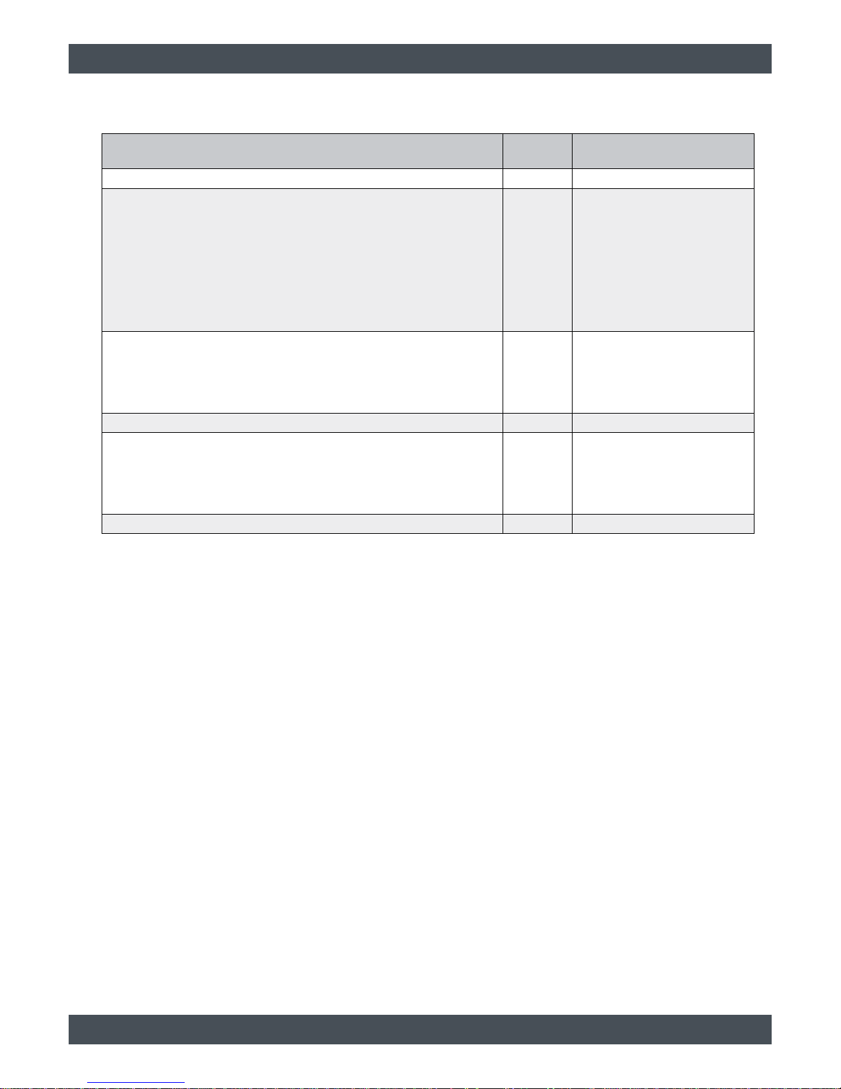
2.1 Technical data
Technical data Unit
Control extension
T2-BT / T2-BTI
Dimensions (WxHxD) mm 291x241x128
Number of inputs/outputs:
Temperature inputs
Analog/digital inputs
230 V outputs
Potential-free outputs
PWM outputs
RS-485 interface
16
2
10
1
4
1
Maximum switching power of the 230 V outputs:
A single 230 V output
Sum of all 230 V outputs
A single potential-free output
W
250
700
500
Supply V / Hz 230 / 50
Energy efficiency calculation factor
Controller class II (no room sensor)
Controller class VI (1-2 room sensors)
Controller class VIII (≥ 3 room sensors)
%
2
4
5
Standby consumption W W 4.4
Page 8

8 www.eta.co.at
Installation
3 Installation
Install T4-0 board in the wall housing
Fasten the T4-0 board onto the spacers on the rear
wall of the wall housing with 4 M3x5 round-headed
screws.
Install T4-0 board
Make the data and power supply connections between
the T4 0-board and the GM-C board.
1 Data line
([GM-C]: [S9],
[MK-E1]: [S15])
2 Power supply
([GM-C]: [S509],
[MK-E1]: [S517])
Fasten wall housing to wall
Fasten the wall housing to the wall using the 4
attachment holes.
1 A = 218.6 mm
2 B = 268.6 mm
Page 9

Specifications Cables
9
4 Specifications
4.1 Cables
CAN bus lines
Install the CAN bus lines according to the provided
specifications and pin assignments.
Use:
• between several circuit boards
• between several ETA boilers
Specifications:
• Total length up to 100 m:
Cable type: 2 x 2 x 0.6 mm STP (shielded twisted
pair) or higher grade
• Total length up to 400 m:
shielded CAT-6 or higher grade
• Maximum total length of all used CAN-bus lines:
400 m
Fig. 4-1: Signal cable (with 2 plugs)
Fig. 4-2: Screw-type terminal block plug
(2 x 0.6 mm STP with single-sided shield)
Fig. 4-3: Screw-type terminal block plug
(2 x 2 x 0.6 mm STP with single-sided shield)
Data cables
Use:
• between base boards and ETAtouch control
panels
Specifications:
• USB type: B
• maximum individual length: 5 m
• maximum total length of all data cables used: 20 m
Fig. 4-4: Data cable (with 2 plugs)
Fig. 4-5: Plug
Fig. 4-6: Socket on the circuit board
Sh Shield
+ Power supply
CH Data line CH
CL Data line CL
GND Earth
Page 10

10 www.eta.co.at
ETAtouch control panel BE-P2 Specifications
4.2 ETAtouch control panel BE-P2
Overview
1 Socket for CAN bus line
2 Terminal for yellow jumper
3 Socket for data line
Set node number on ETAtouch control panel
1. Switch on the entire heating system.
2. On the ETAtouch control panel, increase the authorization level to [Service].
3. Press the [CAN network] button. A window
appears where you can enter the desired node
number.
The values 0 to 7 are permitted for the node
numbers.
4. Restart the entire heating system. The change will
only take effect after the restart.
Page 11

Installation
11
5 Installation
Explanation of symbols
The jumper colours enable visual assignment of
the functions and have no technical relevance.
HACK wood chip boiler
T2-BT control extension with
integrated ETAtouch control panel
ETAtouch control panel BE-P
Node number of the BE-P
Node switch on the circuit board
The circuit board is located at the
end of the CAN bus connection
A yellow jumper must be set.
The circuit board is within the CAN
bus connection.
No yellow jumper may be on the
circuit board.
Page 12

12 www.eta.co.at
T2-BT control extension Installation
5.1 T2-BT control extension
1. Switch off heating system
Isolate the entire heating system from all power
sources, ensure that it cannot be switched back
on, and verify that it is safely isolated from the
power supply.
2. Connect CAN bus lines
Connect the circuit boards with CAN bus lines
using the shortest possible paths.
For details, see page 9
.
Consult the circuit diagrams for details on the
circuit board terminals.
3. Set yellow jumpers
Set one yellow jumper on each of the circuit boards
at the two ends of the CAN bus connection.
The end of the CAN bus connection is the
circuit board on which only one of the CAN
bus sockets is in use.
When both CAN bus sockets are in use, the
circuit board is within the CAN bus
connection and the yellow jumpers must be
removed.
4. Set node numbers
Circuit boards:
Multiple circuit boards of the same design (e.g. 2
GM-C) must have consecutive node numbers.
Set them via the node switch.
ETAtouch control panels:
All ETAtouch control panels must have
consecutive node numbers.
The node number of the ETAtouch cont rol panel
integrated in the ETA boiler is set to the value "0"
at the factory.
Set the node numbers for the external ETAtouch
control panels.
5. Switch on heating system
Switch the entire heating system back on and
check it.
For details, see page 22
.
WARNING!
Maximum length of CAN bus lines
If the maximum length of the CAN bus lines is not
observed, proper operation cannot be ensured!
Ensure that CAN bus-lines do not exceed the
maximum total length of 400 m.
The maximum total length of the CAN bus line is
reduced by 30 m for each overvoltage protection
module.
WARNING!
Configuration errors caused by multiple use of
node numbers with circuit boards and ETAtouch
control panels of the same type
It is impossible to identify circuit boards and ETAtouch
control panels when node numbers are assigned more
than once.
Set the node numbers correctly and conclude by
checking them once again.
Page 13

Installation T2-BT control extension
13
Page 14

14 www.eta.co.at
Electrical connections
6 Electrical connections
Electrical connection must only be made by
qualified specialist personnel
The electrical installation must only be performed
by specialist personnel with the corresponding
qualifications.
Configuration
Switch on the control extension with the main switch
and perform the configuration of the heating system
according to the relevant instructions.
Requirements
Observe the standard and special regulations of local
power supply companies.
For full separation according to the setup require-
ments, a separating device of overvoltage
category III must be installed in the permanent
electrical installation. In most cases, these requirements are fulfilled with a circuit breaker, for example.
For speed-controlled pumps (controled via PWM-
signal), the maximum cable lengths of the pump
manufacturer must be observed.
DANGER!
Electric shock
There are live parts on the circuit boards. If
touched, they can cause injury and
property damage.
Before beginning any work, isolate the system
completely from all power sources, ensure that it
cannot be switched back on, and verify that it is
safely isolated from supply.
CAUTION!
Flexible stranded conductors
If flexible stranded conductors are not used for the
wiring, the contacts in the plug connections will be
subjected to excessive mechanical strain. In this case,
the warranty for the electronics would become null and
void.
Only flexible stranded conductors may be used for
the wiring.
Maximum outputs
Connection diagrams
Fig. 6-1: Mains power input
Fig. 6-2: Analogue input
Fig. 6-3: Digital switch
Mains protection C 13
Mains connection 3 x 1.5²
Type of supply cable H05VV-F 3G 1.5
230 VAC components: 1.0²
Temperature sensors: 0.5² - 1.0²
230 V output
Maximum
power
A single output 250 W
Sum of all outputs 700 W
Potential-free output
(special function)
Maximum
switching
capacity
A single relay output 500 W
Page 15

Electrical connections Potential equalization and overvoltage protection
15
Fig. 6-4: Speed-controlled pump
Fig. 6-5: Special function - pump (with supply extension 230
V)
Fig. 6-6: Special function - changeover valve with three-point
controlling
Fig. 6-7: Special function - burner
Connect system components
Connect the system components according to the
terminal assignment of the configuration.
6.1 Potential equalization and
overvoltage protection
Recommendations for potential equalization and
overvoltage protection
On-site, properly qualified specialist personnel
(electrician) is responsible for a technically
correct earthing concept and proper potential equalization.
In order to avoid electrical potential differentials
between contactable and conductive parts, main
potential equalization will be necessary to protect
against damage caused by electrical shock.
Main potential equalization
All conductive parts within a building (e.g. metal pipes)
must be connected to the foundation ground through
potential equalization bars and potential equalization
cables (minimum diameter for copper: 6 mm²).
Observe national requirements for detailed spec-
ifications and minimum cross-sections of the
lines.
Potential equalization between buildings
Depending on local conditions and the characteristics
of a building's potential equalization, equalization
current may flow between the buildings through the
shielding of the CAN bus connection.
Page 16

16 www.eta.co.at
Potential equalization and overvoltage protection Electrical connections
In order to avoid this, the potential equalization bars of
the buildings should be connected with a thick
potential equalization cable.
Observe national requirements for detailed specifications and minimum cross-sections of the
lines.
Standardized lightning and overvoltage protection
Overvoltage protection that complies with local
conditions, legal requirements and regulations is
recommended for connections between buildings in
addition to potential equalization.
The installation of overvoltage protection may
only be carried out by a specialist.
The overvoltage protection concept must include the
following levels:
• Coarse protection (e.g. lightning rods)
• Medium protection (e.g. integrated distribution
devices)
• Fine protection, if necessary (e.g. power strips with
overvoltage protection)
The protective effects build on each other and are
effective only as a complete overvoltage protection
concept.
WARNING!
Maximum length of CAN bus lines
If the maximum length of the CAN bus lines is not
complied with, the ETAtouch control panel's software
interface may not be displayed correctly.
Ensure that CAN bus-lines do not exceed the
maximum total length of 400 m.
The maximum total length of the CAN bus line is
reduced by 30 m for each overvoltage protection
module.
When using a 4-line control system, an additional
protectively insulated mains adapter is required.
Page 17

Electrical connections Potential equalization and overvoltage protection
17
Page 18

18 www.eta.co.at
Circuit board GM-C2 Electrical connections
6.2 Circuit board GM-C2
Terminal Function Standard assignment
CAN Node CAN-Bus node switch
F1 Fuse T 500 mA (supply 24 V)
S1 230 V supply from circuit board [NT-10VA]: terminal [S51]
S2 230 V output collector pump 2 / secondary pump
S3 230 V output Charging pump for hot water tank
S4 230 V output collector pump 1 / secondary pump
S5 230 V output heating circuit 2: heating circuit pump
S6 230 V output heating circuit 2: heating circuit mixing valve
S7 230 V output heating circuit 1: heating circuit pump
S8 230 V output heating circuit 1: heating circuit mixing valve
S9 Supply extension 230 V to circuit board [MK-E]: terminal [S15]
S10
Potential-free output
(special function)
Diverter valve for solar heating system
S500 T1 Temperature input Solar heating system: secondary flow
S500 T2 Temperature input Solar heating system: primary return
S500 T3 Temperature input Free
S500 T4 Temperature input Free
S500 T5 Temperature input Free
S500 T6 Temperature input Collector
S501 T7 Temperature input Hot water
S501 T8 Temperature input Free
S501 T9 Temperature input Free
S501 T10 Temperature input Free
S501 T11 Temperature input Free
Page 19

Electrical connections Circuit board GM-C2
19
S501 T12 Temperature input Free
S502 T13 Temperature input heating circuit 1: Flow (for buffer operation)
S502 T14 Temperature input Free
S502 LD1 LED output Free
S503 T15 Temperature input heating circuit 2: Flow
S503 T16 Temperature input Primary return (fresh water module 1pump)
S503 LD2 LED output Free
S504 PWM output Speed for pump on terminal [S2]
S505 PWM output Speed for pump on terminal [S3]
S506 PWM output Speed for pump on terminal [S4]
S507 PWM output Speed for pump on terminal [S5]
S508A CAN-Bus Free
S508B CAN-Bus Free
S509 Signal line to circuit board [MK-E]: terminal [S517]
S510 Data line to ETAtouch control panel
S511 RS-485 bus Digital room sensor
S512 Supply 24 V from mains adapter
S513 Analogue or digital input
Flow switch flow rate
(fresh water module 1pump)
S514 Analogue or digital input Free
X2 CAN bus supply GND (for standalone mode)
X3 Boot jumper
X4 CAN-Bus terminal resistor
X5 RS-485 terminator resistor
X24 CAN bus supply +24 V (for standalone mode)
Terminal Function Standard assignment
Terminals marked with this symbol are not pre-wired.
Page 20

20 www.eta.co.at
NT-10VA circuit board Electrical connections
6.3 NT-10VA circuit board
Terminal Function Default assignment
F2 Fuse 230 V, T 6,3 A
X1 Supply 230 V Mains power input
X2 230 V input Mains switch
X3 Supply extension 24 V to circuit board [GM-C]: terminal [S512]
X4 Supply extension 230 V to circuit board [GM-C]: terminal [S1]
Terminals marked with this symbol are not pre-wired.
Page 21

Electrical connections MK-E1 circuit board
21
6.4 MK-E1 circuit board
Terminal Function Default assignment
S15 Supply 230 V from circuit board [GM-C]: terminal [S9]
S16 230 V output heating circuit 3: heating circuit pump
S17 230 V output heating circuit 3: heating circuit mixing valve
S18 230 V output heating circuit 4: heating circuit pump
S19 230 V output heating circuit 4: heating circuit mixing valve
S515 T17 Temperature input heating circuit 3: Flow
S515 T18 Temperature input Free
S515 LD3 LED output Free
S516 T19 Temperature input heating circuit 4: Flow
S516 T20 Temperature input Free
S516 LD4 LED output Free
S517 Signal line to circuit board [GM-C]: terminal [S509]
Terminals marked with this symbol are not pre-wired.
Page 22

22 www.eta.co.at
Concluding activities
7 Concluding activities
Check node numbers
1. On the ETATouch control panel, the system
settings menu is opened by tapping the
symbol (in the lower left of the screen).
2. Press the [Version overview] button. Compare
the node numbers of the circuit boards and the
previously configured ETAtouch control panels
with the numbers that appear in this window.
[Touchscreen(s)]:
Here, all available ETAtouch control panels are
displayed with their assigned node numbers.
[Circuit boards]:
Here, all available circuit boards are displayed with
their assigned node numbers.
If any circuit boards or ETAtouch control panels
are not displayed in this window, the configuration
of the corresponding node numbers needs to be
checked and corrected.
3. Close the window.
Page 23

Page 24

www.eta.co.at
www.eta.co.at/downloads
DOWNLOAD
 Loading...