

Page 1
Instruction Manual
Controller CPC10PB
Page 2

2
Contents
2 General information ..........................................................................................................................4
2.1 Safety instructions .....................................................................................................................4
2.2 Qualified personnel .................................................................................................................... 4
2.3 Use ............................................................................................................................................. 4
2.4 Delivery state .............................................................................................................................4
3 General description ...........................................................................................................................5
3.1 Design of the entire system .......................................................................................................6
3.2 Dimensions of version CPC10PB-T1 ......................................................................................... 7
3.3 Dimensions of version CPC10PB-T4 ......................................................................................... 7
3.4 Status indication and terminals ..................................................................................................8
3.4.1 Terminals for voltage supply ........................................................................................... 8
3.4.2 Connector socket for the ELBus®, connector sockets X51, X52, X53, X54 .................8
3.4.3 USB service interface, terminals X61 .............................................................................9
3.4.4 Bus interfaces to PROFIBUS-DP, connector socket X81 ...............................................9
3.4.5 LED PWR ........................................................................................................................ 9
3.4.6 LED CE ...........................................................................................................................9
3.4.7 LED CM...........................................................................................................................9
3.4.8 LED MS ........................................................................................................................... 9
3.4.9 LED NS ...........................................................................................................................9
4 Mounting and installation ................................................................................................................. 10
4.1 Mounting of the system .............................................................................................................10
4.2 Wiring and connecting the modules ..........................................................................................10
4.2.1 Supply of terminal strip X41 ............................................................................................10
4.2.2 ELBus® connector sockets to power distribution system (-X51, -X52, -X53, -X54) ..... 11
4.2.3 USB service and maintenance interface (-X61) .............................................................. 12
4.2.4 PROFIBUS-DP interface (-X81) ......................................................................................12
5 Operating modes of the CPC10PB controller .................................................................................12
5.1 Operating mode: Start-up mode ................................................................................................ 12
5.2 Operating mode: System error mode ........................................................................................12
5.3 Operating mode: Configuration error mode ............................................................................... 12
5.4 Operating mode: Stand-alone mode .........................................................................................12
5.5 Operating mode: Slave mode .................................................................................................... 13
5.6 Operating mode: Firmware update mode .................................................................................. 13
5.7 Signalling of the various operating modes .................................................................................13
6 Basic functions of the entire system ............................................................................................... 14
6.1 Internal cycle times .................................................................................................................... 14
6.2 Hot swap of circuit protectors....................................................................................................14
6.3 Communication via the USB service interface...........................................................................15
7 Communication via PROFIBUS-DP ................................................................................................. 15
7.1 Module I/O data CPC10PB device ............................................................................................16
7.2 Module control measuring values .............................................................................................. 16
7.2.1 Status circuit protector ...................................................................................................17
7.2.2 Control circuit protector .................................................................................................. 17
7.2.3 Measuring values circuit protector .................................................................................18
7.3 Module control ........................................................................................................................... 18
Page 3

3
8 Non-cyclical data ..............................................................................................................................19
8.1 Configuration data CPC10PB controller .................................................................................... 20
8.2 Configuration data slot for circuit protector ............................................................................... 21
8.3 Device information CPC10PB controller .................................................................................... 22
8.3.1 Device type ..................................................................................................................... 22
8.3.2 Serial number ..................................................................................................................22
8.3.3 Hardware version ............................................................................................................ 23
8.3.4 Software version ............................................................................................................. 23
8.4 Device information circuit protector ........................................................................................... 24
8.4.1 Device type ..................................................................................................................... 24
8.4.2 Serial number ..................................................................................................................24
8.4.3 Hardware version ............................................................................................................ 24
8.4.4 Software version ............................................................................................................. 25
8.5 Device parameters circuit protector ...........................................................................................25
8.5.1 Current rating .................................................................................................................. 25
8.5.2 Switch-on behaviour .......................................................................................................26
8.5.3 Overload disconnection .................................................................................................. 26
8.5.4 Trip time at overload ....................................................................................................... 26
8.5.5 Trip time at short circuit .................................................................................................. 27
8.5.6 ON delay ......................................................................................................................... 27
8.5.7 Limit value load current ..................................................................................................27
8.5.8 Hysteresis of the limit value ............................................................................................ 28
8.6 Action commands circuit protector ...........................................................................................28
8.7 Event messages circuit protector ..............................................................................................29
8.8 Diagnostic messages circuit protector ......................................................................................29
8.8.1 Error memory .................................................................................................................. 29
8.8.2 Trip counter ..................................................................................................................... 30
8.8.3 Reason for trip ................................................................................................................ 30
8.8.4 Operating voltage ...........................................................................................................30
8.8.5 Temperature .................................................................................................................... 31
8.8.6 Internal communication messages ................................................................................. 31
9 Appendix ............................................................................................................................................32
9.1 List of picture .............................................................................................................................32
9.2 Technical data ............................................................................................................................ 33
9.3 Subject index ............................................................................................................................. 33
Page 4

4
2 General information
2.1 Safety instructions
This manual points out possible danger for your personal safety and gives instruction how to avoid property
damage. The following safety symbols are used to draw the reader's attention to the safety instructions included in
this manual.
Danger!
There is a threat to life or health
unless the following safety measures are observed.
Caution!
Machinery, materials or the environment might get damaged
unless the following safety measures are observed.
Note
Information is provided to allow a better understanding.
Caution:
Electrostatically sensitive devices (ESD).
Devices must exclusively be opened by the manufacturer.
Waste management guidelines
Packaging can be recycled and should generally be
brought to re-use.
2.2 Qualified personnel
This user manual must exclusively be used by qualified personnel, who are able - based on their training and
experience - to realise arising problems when handling the product and to avoid related hazards. These persons
have to ensure that the use of the product described here meets the safety requirements as well as the
requirements of the presently valid directives, standards and laws.
2.3 Use
The product is part of a continuous enhancement process. Therefore there might be deviations between the
product in hand and this documentation. These deviations will be remedied by a regular review and resulting
corrections in future editions. The right to make changes without notice is reserved. Error and omissions
excepted.
2.4 Delivery state
The product is supplied with a defined hardware and software configuration. Any changes in excess of the
documented options are not permitted and lead to liability exclusion.
Page 5

5
3 General description
Modern factory automation and process control has ever more complex and sophisticated requirements. Control
is no longer the sole focus, but monitoring of components and processes becomes more and more important. This
is exactly the target application area of the intelligent and bus-capable power distribution system ControlPlex®. It
serves for the protection of industrial applications as well for monitoring and control. The bus controller CPC10PB
is the core of the system and provides the data exchange between superordinate and subordinate components.
These are on the one hand programmable control units and on the other hand it is the power distribution system
SVS201-PWR-xx, fitted with the electronic circuit protectors ESX50D-S1-xx. The bus controller CPC10PB can be
connected with four independent power distribution systems SVS201-PWR-xx and offers the possibility of
communication with up to 96 electronic circuit protectors. Communication options comprise transmission of the
operating condition, of measuring values and device information regarding the connected components, but also
changes of the product-specific parameters such as current ratings and execution of actions, e.g. ON and OFF
operation.
Information can be transmitted in a cyclical or non-cyclical mode to the superordinate control system or via an
available service interface to the connected service computer. If no connection is available to a superordinate
control unit, this will have no effect on the behaviour of the connected circuit protectors. The bus controller is
able to ensure their functionality even without a connection to a superordinate control unit. The saved parameters
will be used for this purpose.
The bus-capable power distribution system ControlPlex
®
offers the well-known E-T-A quality and reliability
with regard to overcurrent protection in combination with the innovative functions on the score of automation
technology.
Page 6
6
3.1 Design of the entire system
The bus controller CPC10PB-Tx is the centre of the ControlPlex
®
system. Thanks to its interfaces, it allows
a consistent communication between the power distribution systems SVS201-PWR-xx with the plugged-in
electronic circuit protectors ESX50D-S1xx and the superordinate control units as well as the service computer.
The PROFIBUS-DP interface to the superordinate control unit features a 9-pin SUB-D connector. It allows
connection of the required control unit with the ControlPlex
®
system, thus enabling display and analysis of
the individual measuring values as well as diagnosis and control of the individual electronic circuit protectors. The
same functions are also made available at the USB service interface. Should there be any changes in the
automation system, all required measuring values of the electronic circuit protectors can be observed by
means of the service interface and, if this functionality has been released by the superordinate control unit,
they can be adjusted to the device parameters. This enables the user to have unrestricted access to the
safety-relevant functions even in the event of an interruption. Any occurring failures will be detected quickly
and can be remedied without delay. The CP system effectively reduces system downtimes and significantly
increases productivity.
The interface to the up to four power distribution boards SVS201-PWR-xx is realised with local bus defined
specially in-house at E-T-A called ELBus® . It transmits all cyclical and non-cyclical data in a cycle time of
230 - 730 milliseconds (depending on the version of the up to four power distribution boards SVS201-PWR-xx).
The power boards are mutually independent and are addressed in parallel by the communication unit. Each
specific version of the power distribution board SVS201-PWR-xx can be selected by the customers in available slot
numbers of four, eight, twelve, sixteen and twenty-four electronic circuit protectors.
Power Distribution board 1
ELBus®
ELBus®
ELBus®
ELBus®
Power Distribution board 2
Power Distribution board 3
Power Distribution board 4
COM-1
CPC10PB-T4
COM-2
COM-3
COM-4
X51
X52
X53
X54
X61X81
NSMSCM
CE
DC
24 V
X41PWR
+ +0 V 0 V
G E R M A N Y
Typ: SVS201-PWR-16-001
DC24V/40A X31
1+ 2+ 1- 2- PE
X50
COM
F1 F2 F3 F4 F5 F6 F7 F8 F9 F10 F11 F12 F13 F14 F15 F16
X1 X2 X3 X4 X5 X6 X7 X8 X9 X10 X11 X12 X13 X14 X15 X16
1+ 2+ 1+ 2+ 1+ 2+ 1+ 2+ 1+ 2+ 1+ 2+ 1+ 2+ 1+ 2+ 1+ 2+ 1+ 2+ 1+ 2+ 1+ 2+ 1+ 2+ 1+ 2+ 1+ 2+ 1+ 2+
1- 2- 1- 2- 1- 2- 1- 2- 1- 2- 1- 2- 1- 2- 1- 2- 1- 2- 1- 2- 1- 2- 1- 2- 1- 2- 1- 2- 1- 2- 1- 2-
1/ELB
2/+24V
3/GND
Made in Germany
SVS201-PWR
CPC10PB-T4*
bus interface
PROFIBUS-DP
USB maintance
and service interface
Electronic circuit protector
ESX50D-S1-xxx plug-in type
*Only one power distribution board can be
connected when using a CPC10PB-T1
Control of
ControlPlex®Tools
Service laptop
ControlPlex®Views
on
off
I
N
/
A
ESX50D
-S110DC24V
r
e
s
e
t
fig. 1: System overview
Page 7
7
3.2 Dimensions of version CPC10PB-T1
CPC
10PB
-T1
X61X81 X51/COM-1
NSMSCM
CE
DC
24 V
X41PWR
114,5
22,6
99
Provide space for
connectors and cables
+ +0 V 0 V
DIN rail EN 60715-35x7,5
(not included)
fig. 2: CPC10PB-T1 (1-Port)
3.3 Dimensions of version CPC10PB-T4
114,5
45,2
99
Provide space for
connectors and cables
COM-1
CPC10PB-T4
COM-2
COM-3
COM-4
X51
X52
X53
X54
X61X81
NSMSCM
CE
DC
24 V
X41PWR
+ + 0 V 0 V
DIN rail EN 60715-35x7,5
(not included)
fig. 3: CPC10PB-T4 (4-Port)
Page 8
8
3.4 Status indication and terminals
Bus Controller
CPC10PB-T1
X81
bus interface
PROFIBUS-DP
Address rotary switch
X61
USB service interface
LED PWR
CPC
10PB
-T1
COM-1
CPC10PB-T4
COM-2
COM-3
COM-4
X51
X52
X53
X54
X61 X81 X51/COM-1
NSMSCM
CE
DC
24 V
X41PWR
X61
X81
NSMSCM
CE
DC
24 V
X41PWR
Bus Controller
CPC10PB-T4
+ +0 V 0 V
+ + 0 V 0 V
X41
voltage supply DC 24 V
LED NS
LED MS
LED CM
LED CE
X51, X52,
X53, X54
ELBus®connectors
fig. 4: Status indication and terminals CPC10PB-T4
3.4.1 Terminals for voltage supply
The operating voltage of the device is 24 V DC. Faultless operation of the device is ensured in a voltage range
of 18 V to 32 V. Current consumption on duty is typically 60 mA.
Using a supply voltage outside the indicated operating range can cause malfunctions or destruction
of the device.
3.4.2 Connector socket for the ELBus®, connector sockets X51, X52, X53, X54
These connector sockets served for connecting the communication unit CPC10 with up to four power distribution
boards SVS201-PWR-xx. Connection of the devices is realised with a one-to-one wiring mode. Preferably it shall
be realised with a cable type H07V-K 1.5mm². The cable does not have to be shielded specially. The cable length
between the bus controller and the power distribution board SVS201-PWR-xx must not exceed 2 m.
Use of the terminals for applications not provided for in the operation manual or improper connection
can lead to malfunction or destruction of the device.
1. Data line ELBus® ELB
2. Supply voltage ELBus® + 24 V
3. Supply voltage ELBus® GND
fig. 5: ELBus® connection
If the terminals of the various power distribution boards SVS201-PWR-xx are swapped, e.g. exchange
X51 with X52, the connected electronic circuit protectors will automatically be parameterised anew.
Page 9

9
3.4.3 USB service interface, terminals X61
The USB interface serves for connection of the service computer. By means of the available user software
ControlPlex®Views it is possible to import the measuring values of the individual circuit protectors, to change
parameters and to switch the devices on or off. The connection is realised by means of USB-2.0 type B. The
length must be less than 3 m. In the event of a bus communication with the superordinate control unit, the
user software has only reader access. If a change of the device parameters should be made possible on behalf of
the user software, this has to be explicitly released by the superordinate control unit.
3.4.4 Bus interfaces to PROFIBUS-DP, connector socket X81
The PROFIBUS-DP connection is realised via a 9-pin SUB-D connector. It allows direct connection of the
device with other PROFIBUS-DP participants. For mounting and special selection of cables and connectors
please see mounting guideline of the PNO.
3.4.5 LED PWR
The PWR diode lights up green if voltage is applied.
3.4.6 LED CE
The LED CE shows the status of the communication unit. For more detailed information please see chapter
»Signalling of various operating modes«.
3.4.7 LED CM
The LED CM shows the status of the communication between the communication unit and electronic circuit
protector. For more detailed information please see chapter »Signalling of various operating modes«.
3.4.8 LED MS
The LED MS shows the status of the internal PROFIBUS-DP communication module.
3.4.9 LED NS
The LED NS shows the network status of the communication of the internal PROFIBUS-DP communication
module to the PROFIBUS-DP master.
Page 10

10
4 Mounting and installation
4.1 Mounting of the system
The preferred mounting position of the ControlPlex® system is horizontal.
fig. 6: Installation drawing
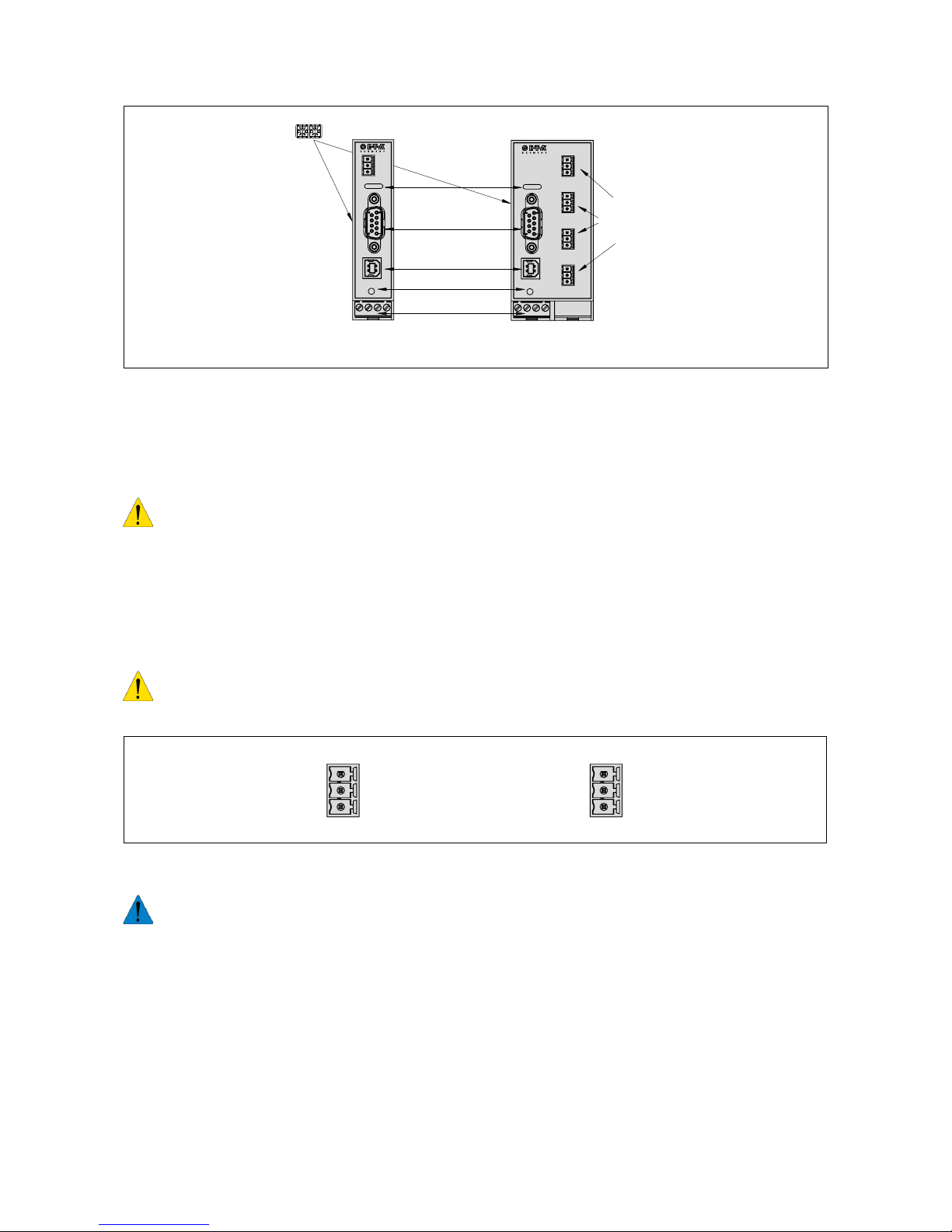
4.2 Wiring and connecting the modules
bus controller
CPC10PB-T1
CPC
10PB
-T1
COM-1
CPC10PB-T4
COM-2
COM-3
COM-4
X51
X52
X53
X54
X61 X81 X51/COM-1
NSMSCM
CE
DC
24 V
X41PWR
X61
X81
NSMSCM
CE
DC
24 V
X41PWR
bus controller
CPC10PB-T4
+ +0 V 0 V
+ + 0 V 0 V
fig. 7: Terminals CPC10PB-T1 and -T4
4.2.1 Supply of terminal strip X41
Rated voltage: DC 24 V (18...32 V)
Current ratings: typically 60 mA
Terminals: 4 x screw terminals, (+/+/0 V/0 V)
Max. cable cross section max. 2.5 mm
2
Flexible with wire end ferrule without plastic sleeve 0.25 mm – 1.5 mm
2
Flexible with wire end ferrule without plastic sleeve 0.25 mm – 2.5 mm
2
Wire stripping length 7 mm
Tightening torque 0.5 to 0.6 Nm
Page 11

11
4.2.2 ELBus® connector sockets to power distribution system (-X51, -X52, -X53, -X54)
1. Data line ELBus® ELB
2. Supply voltage ELBus® + 24 V
3. Supply voltage ELBus® GND
fig. 8: Terminals of the ELBus® connectors
X51 COM-1: terminal for first power distribution board SVS201-PWR-xx
Cable length: max. 2 m
Typically: H07V-K 1.5 mm
2
Connector 1: ELBus® ELB Data line
Connector 2:
ELBus®
DC + 24 V
Connector 3:
ELBus®
GND
X52 COM-2: terminal for second distribution board SVS201-PWR-xx
Cable length: max. 2 m
Typically: H07V-K 1.5 mm²
Connector 1: ELBus® ELB Data line
Connector 2:
ELBus®
DC + 24 V
Connector 3:
ELBus®
GND
(only with CPC10PN-T4)
X53 COM-3: terminal for third distribution board SVS201-PWR-xx
Cable length: max. 2 m
Typically: H07V-K 1.5 mm²
Connector 1: ELBus® ELB Data line
Connector 2:
ELBus®
DC + 24 V
Connector 3: ELBus® GND
(only with CPC10PN-T4)
X54 COM-4: terminal for fourth distribution board SVS201-PWR-xx
Cable length: max. 2 m
Typically: H07V-K 1.5 mm²
Connector 1: ELBus® ELB Data line
Connector 2:
ELBus®
DC +24 V
Connector 3:
ELBus®
GND
(only with CPC10PN-T4)
Page 12

12
4.2.3 USB service and maintenance interface (-X61)
X61 Connection to a PC for communication with the user software ControlPlex®Views
Type: USB-2.0 Type B
Cable length: max. 2.5 m
4.2.4 PROFIBUS-DP interface (-X81)
X81 Connection to bus system PROFINET-DP
Type: Connector 9-pole SUB-D
When wiring and connecting to the bus system PROFIBUS-DP the installation and wiring regulations of
the PROFIBUS-DP User Organisation (PNO) have to be observed.
5 Operating modes of the CPC10PB controller
5.1 Operating mode: Start-up mode
The bus controller is initialised by applying the supply voltage. The device will carry out implemented programme
memory tests and self test routines. During this time a communication via the interfaces is not possible.
5.2 Operating mode: System error mode
If a failure is detected during the self test routines, the bus controller will change into operating mode System
Error. This operating mode can only be discontinued by way of re-starting the device and it prevents the data
exchange via the interfaces. If the bus controller is in the aforementioned operating mode, it is unable to
control the electronic circuit protectors and these will stay in the stand-alone mode (overcurrent protection).
5.3 Operating mode: Configuration error mode
If there are no valid or invalid configuration data available in the bus controller, it will change into the Configuration
Error Mode. This operating mode only allows non-cyclical data exchange. Cyclical data exchange is prevented.
Leave this operating mode upon receipt of the correct slot parameters and configuration data.
5.4 Operating mode: Stand-alone mode
In normal duty there is a connection between the bus controller and the superordinate control unit. Thus the
electronic circuit protectors are controlled and their parameterss are changed by the superordinate control unit.
Should the communication between both participants fail, this has no influence on the protective function of the
circuit protectors. In this case the bus controller CPC10 will automatically adopt the control and parameterisation of
the electronic circuit protectors, because are required data sets are saved within the CPC10. By means of the user
software ControlPlex®Views the electronic circuit protectors, their status and parameters can be accessed via the
maintenance and service interface. It is thus possible to change e.g. parameter data of the various electronic circuit
protectors. If the failure on the communication level is remedied, this operating mode will be left and the superordinate
control unit will take over control again as master. If during this time a parameter was changed while there was no
communication, this will be signalled to the superordinate control unit. In this case the user can correspondingly
define the control behaviour and it can be programmed in the programmable control unit. This allows the user to
select a reaction meeting his requirements.
Page 13

13
5.5 Operating mode: Slave mode
In this operating mode the bus controller CPC10 is involved in a PROFIBUS-DP system. Communication to the
bus controller CPC10 works faultlessly and the controller can be addressed and controlled by the superordinate
control unit.
The behaviour of the bus controller with simultaneous use of a field bus interface and the USB service and
maintenance interface can be determined by means of the configuration of the device in the superordinate
control unit. It can be pre-selected there that the USB service and maintenance interface is granted either
only reader access or reader and editor access. In the event of editor access, changes of the parameterisation
of the electronic circuit protectors can be carried out in parameter selection to the field bus system. These
parameter changes will then be advised to the superordinate control system and can be adopted by it or also
overwritten. The user can select the behaviour accordingly.
5.6 Operating mode: Firmware update mode
The devices are supplied with a software programmed according to their functionality. If the functions of the
devices are extended, this will be carried out in the firmware. It is therefore necessary to carry out a firmware
update if the new functionality shall be used. More detailed information regarding the firmware update are
made available in the user manual of the software ControlPlex®Views.
5.7 Signalling of the various operating modes
The different operating modes of the bus controller CPC10 are indicated as follows:
Operating mode Indication of operating mode
LED CM LED CE LED PWR
Start-up mode yellow yellow green
System error mode yellow red green
Configuration error mode yellow red/OFF* green
stand-alone mode yellow - green
Slave mode green red green
Firmware update red/OFF* red/OFF* red/OFF*
* blinking
fig. 9: List of the available operating modes
Page 14

14
6 Basic functions of the entire system
6.1 Internal cycle times
The cycle time of the system depends on the number of data to be transmitted between the bus controller
CPC10 as well as the number of slots intended on the power distribution system for the electronic circuit
protectors ESX50D-S. The cycle time decreases when using a power distribution board with four slots as
opposed to the cycle time with a power distribution system with 24 slots from 730 ms to 230 ms. During the
aforementioned period the status, the output voltage and the load current of each circuit protector is cyclically
transmitted to the CPC10. This has to be seen independently of the number of connected power distribution
boards SVS201-PWR with which the CPC10 communicates in parallel. The cycle time of the entire system
goes by the longest cycle time of the designed power distribution board. If for instance a power distribution
board with 16 and three more with 8 slots are connected to a CPC10PB-T4, the cycle time will comply with
the 16-slot-board and will thus be 530 ms for all four connected power distribution systems.
It is possible to choose the data quantity for the communication to the superordinate control unit. This can
be achieved by using the different data models. It is therefore possible to transmit either the status, the measuring
values for the load current and the output voltage of the electronic circuit protector or to only send the circuit
protector status to the superordinate control unit. The choice between the various data models is made available to
the user in the GSD file of the control system. These are configuration data which are transmitted to the store
programme control by means of the hardware configuration of the CPC10.
fig. 10: Cycle times of the system
6.2 Hot swap of circuit protectors
The electronic circuit protectors ESX50D-S can be plugged into the power distribution board SVS201-PWR-xx at
any time. The ON/OFF button of the electronic circuit protector has to be in the OFF position.
For safety reasons the electronic circuit protectors ESX50D-S must only be plugged in in the OFF
condition.
Page 15

15
After plugging in a circuit protector, it will automatically be parameterised if parameters are available for the
slot in question. Transmission of the parameters will be without interruption of the cyclical data exchange between
the communication unit SVS200-COM and the electronic circuit protector ESX50D-Sxx. After switching the device
on with the ON/OFF button the electronic circuit protector is ready for use.
6.3 Communication via the USB service interface
In addition to the PROFIBUS-DP interface, a maintenance and service interface will also be made available
to the user. It enables direct access to the bus controller CPC10PB. This is also possible when there is no
communication via the field bus interface. If the device is in the stand-alone mode, the user can access the
bus controller and the connected electronic circuit protectors at any time (reading or editing) via this interface. The
access in the slave mode can be parameterised by the user via the field bus interface. The delivery conditon
allows only reading access. Editor access has to explicitly be released by the user in the superordinate control
unit.
If the slot parameters are changed, the change will be signalled to the superordinate control unit. The user will
thus be able to process these changes in his control accordingly.
For parameterisation of the individual electronic circuit protectors the corresponding user software
ControlPlex®Views is available for the USB service interface. This software is available for download from
the E-T-A website and can be installed on a Windows® computer. The user software is described separately
in another manual.
7 Communication via PROFIBUS-DP
Depending on the designed configuration a different quantity of data bytes will be exchanged in the cyclical
data traffic between master and slave.
The system allows determination which data volume can be exchanged. Two different modules are selectable
per PWR board with different configurations (4, 8, 12, 16, 20 or 24 slots for the circuit protectors).
The module Control-Measure exchanges I/O data (status/control) and measuring values of the individual circuit
protectors with the master. The module Control only exchanges I/O data (status/control) of the individual circuit
protectors with the master.
The GSD file made available for the projecting tool allows the related configuration, the system recognises all
permitted configurations and processes the cyclical data defined in the projection.
Only the module I/O data CPC10PB-Device is firmly pre-set and cannot be removed because the input bytes
hold vital failure and diagnoses information as described in the following.
The maximum number of input and output data is limited to 244 bytes each.
Not more than 368 bytes must be exchanged in total.
Page 16

16
7.1 Module I/O data CPC10PB device
The 2 bytes input data contain the following global error and diagnostic messages. This module does not
contain any output data.
Value range: 0 – 65535
Data length: 2 byte (unsigned integer)
Byte[0] Low Bit 7 Bit 6 Bit 5 Bit 4 Bit 3 Bit 2 Bit 1 Bit 0
description 128 64 32 16 8 4 2 1
value 0/1 0/1 0/1 0/1 0/1 0/1 0/1 0/1
no configuration data available 0/1*
invalid configuration data 0/1*
reserve
reserve
command buffer overflow 0/1*
reserve
reserve
no communication with at least one
PWR board
0/1*
Byte[1] low Bit 15 Bit 14 Bit 13 Bit 12 Bit 11 Bit 10 Bit 9 Bit 8
description 128 64 32 16 8 4 2 1
value 0/1 0/1 0/1 0/1 0/1 0/1 0/1 0/1
reserve
CPC10PB temporary error 0/1*
CPC10PB hardware error 0/1*
reserve
reserve
reserve
network error 0/1*
writing via USB blocked 0/1*
* status not set = 0 / status set = 1
fig. 11: Input data for global error and diagnostic messages
7.2 Module control measuring values
Depending on the configuration (number of slots for circuit protectors) five bytes input data with the status of
the circuit protectors (1 byte) and with the measuring values of load current and load voltage (4 byte) of the
corresponding circuit protector are made available. Control of a circuit protector requires 1 byte output data.
In the event of a power module with 16 slots, 80 bytes input data and 16 bytes output data are exchanged.
Addressing will be in accordance with the configured slots N of the circuit protectors.
byte address [0…N-1] Status/Control.
byte address [N…4*N-1] measuring values.
Page 17

17
7.2.1 Status circuit protector
Design of the input byte per circuit protector slot is as follows (status circuit protector):
Value range: 0 – 255
Data length: 1 byte (unsigned character)
Byte[0] low Bit 7 Bit 6 Bit 5 Bit 4 Bit 3 Bit 2 Bit 1 Bit 0
description 128 64 32 16 8 4 2 1
value 0/1 0/1 0/1 0/1 0/1 0/1 0/1 0/1
status load output 0/1*
status short circuit 0/1*
status overload 0/1*
status undervoltage 0/1*
status overvoltage 0/1*
status excess temperature 0/1*
status limit value current 0/1*
status event 0/1*
* status not set = 0 / status set = 1
fig. 12: Input byte circuit protector - status
7.2.2 Control circuit protector
Design of the output byte per circuit protector slot is as follows (control circuit protector):
Value range: switch load output on/off, reset load output, output data valid/invalid
Data length: 1 byte (unsigned character)
Byte[0] low Bit 7 Bit 6 Bit 5 Bit 4 Bit 3 Bit 2 Bit 1 Bit 0
description 128 64 32 16 8 4 2 1
value 0/1 0/1 0/1 0/1 0/1 0/1 0/1 0/1
load output ON/OFF
load output
0/1*
reset load output 1**
reserve
reserve
reserve
reserve
reserve
output data valid/invalid 0/1**
* switch on load output = 1 / switch off load output = 0
** reaction only to rising flank (bit 1 requires value ZERO in the previous cycle)
*** output data valid = 1 / output data invalid = 0
fig. 13: Output byte circuit protector - control
Page 18

18
7.2.3 Measuring values circuit protector
The measuring values contain the data of load current and load voltage of a circuit protector. The sequence
of the measuring values is load current (2 bytes), followed by load voltage (2 bytes)
Load current circuit protector
Design of the input bytes per circuit protector slot is as follows (measuring value load current):
Value range: 0 – 65535
Data length: 2 byte (unsigned integer)
Byte[0] (LOW) Bit 7 Bit 6 Bit 5 Bit 4 Bit 3 Bit 2 Bit 1 Bit 0
Description 128 64 32 16 8 4 2 1
Value 0/1 0/1 0/1 0/1 0/1 0/1 0/1 0/1
Byte[1] (HIGH) Bit 15 Bit 14 Bit 13 Bit 12 Bit 11 Bit 10 Bit 9 Bit 8
Description 327688 16384 8192 4096 2048 1024 512 256
Value 0/1 0/1 0/1 0/1 0/1 0/1 0/1 0/1
The load current is made available as a standardised 16-bit-value with a solution of 10 mA.
Example: Measuring value load current = 1025 ➞ real measuring value = 10.25 A
fig. 14: Input byte load current circuit protector
load voltage circuit protector
Design of the input bytes per circuit protector slot is as follows (measuring value load voltage):
Value range: 0 – 65535
Data length: 2 byte (unsigned integer)
Byte[2] (LOW) Bit 7 Bit 6 Bit 5 Bit 4 Bit 3 Bit 2 Bit 1 Bit 0
Description 128 64 32 16 8 4 2 1
Value 0/1 0/1 0/1 0/1 0/1 0/1 0/1 0/1
Byte[3] (HIGH) Bit 15 Bit 14 Bit 13 Bit 12 Bit 11 Bit 10 Bit 9 Bit 8
Description 327688 16384 8192 4096 2048 1024 512 256
Value 0/1 0/1 0/1 0/1 0/1 0/1 0/1 0/1
The load voltage is made available as a standardised 16-bit-value with a solution of 10 mV.
Example: Measuring value load voltage = 2456 ➞ real measuring value = 24.56 V
fig. 15: Input byte load voltage circuit protector
7.3 Module control
Depending on the configuration (number of slots for circuit protectors) one byte input data with the status of
the circuit protector and one byte output data for controlling the circuit protectors are exchanged.
In the event of a power module with 16 slots, 16 bytes input data and 16 bytes output data are exchanged.
Addressing will be in accordance with the configured slots N of the circuit protectors.
Byte address [0…N-1] Status/Control.
Status circuit protector (see chapter "Module control-measuring values")
Page 19
19
8 Non-cyclical data
Non-cyclical PROFIBUS-DP services allow exchange of more data with the CPC10PB controller and the
circuit protectors. The non-cyclical access also enables direct addressing of a circuit protector on a SVS201-PWR
board.
Addressing of the data is by indication of the hardware identifier and of the index.
With ControlPlex® the hardware identifier holds the CPC10PB controller as well as the pertinent SVS201-PWR
board, the index holds the slot number and parameter index.
The index consists of the slot number and the parameter index.
product type decimal place description
slot of
circuit protector
Decimal numbers
10
2
and 10
1
slot of circuit protector on the SVS201-PWR board.
Valid value range: 00…24
parameter index Decimal numbers
10
0
The parameter index defines the data range and the data
type of the data to be read or written.
Valid value range: 0…9
fig. 16: Index structure
Example: Index for reading device information of the circuit protector in slot 2.
02 1
parameter index
slot number
The parameters index is assigned to the following non-cyclical data areas:
parameter
Index
slot
number
number of
data bytes
reading (R)
writing (W)
description
0 01…24 8 R/W parameter of a circuit protector (see chapter 8.5)
1 00 9 R device information of CPC10PB
controller see chapter 8.3
1 01/24 9 R device information of a circuit protector
(see chapter 8.4)
2 00 6 R/W configuration data CPC10PB
controller see chapter 8.1
2 01...24 6 R/W configuration data of a slot for the circuit
protector (see chapter 0)
3 01...24 1 R event of a circuit protector
(see chapter 8.7)
4 01...24 1 W action commands for a circuit protector
(see chapter 8.6)
4 00 1 W action commands for all circuit protectors on
a PWR board (see chapter 8.6)
5 01...24 9 R diagnostic data of a circuit protector
(see chapter 8.8)
fig. 17: Set-up parameter index
Page 20

20
8.1 Configuration data CPC10PB controller
These bytes hold the configuration data for the CPC10PB controller.
6 bytes are exchanged non-cyclically as configuration data for the CPC10PB controller. Currently only the
first byte holds configuration options. The other bytes presently serve as placeholders for possible later extensions
and are not evaluated.
Byte[0] holds configuration options of the service interface (USB) as well as about the behaviour of the circuit
protectors when the connection to the master control is interrupted.
Value range: 0 – 255
Default value: 03
Data length: 1 byte (unsigned character)
Byte[0 ] Bit 7 Bit 6 Bit 5 Bit 4 Bit 3 Bit 2 Bit 1 Bit 0
description 128 64 32 16 8 4 2 1
value 0/1 0/1 0/1 0/1 0/1 0/1 0/1 0/1
write instruction via USB
(service interface)
0/1*
offline behaviour (low/freeze)
0/1**
power saving mode
0/1**
reserve
reserve
reserve
reserve
reserve
0/1**
* writing via USB blocked = 0 / writing via USB released = 1
** Low = 0 (all load outputs of the circuit protectors are switched off and the CPC10PB controller
changes into the the operating mode stand-alone).
** Freeze = 1 (all load outputs of the circuit protectors keep their current state and the
CPC10PB controller changes into the the operating mode stand-alone).
*** power saving mode deactivated = 0 / power saving mode activated = 1
fig. 18: Configuration data CPC10PB
Byte[1] – Byte[5] do not contain information.
Value range: Default value: Data length: 5 bytes (unsigned character)
Byte[1] – Byte[5] Bit 7 Bit 6 Bit 5 Bit 4 Bit 3 Bit 2 Bit 1 Bit 0
description 128 64 32 16 8 4 2 1
value 0/1 0/1 0/1 0/1 0/1 0/1 0/1 0/1
reserve
- - - - - - - -
fig. 19: Configuration data reserve bytes
Page 21

21
8.2 Configuration data slot for circuit protector
These bytes hold configuration data for the slots of the circuit protectors.
6 bytes are exchanged non-cyclically as configuration data for the slots. The first byte holds the device type
which shall be plugged into the corresponding slot. The second byte holds information about whether the
slot is released or locked out. Communication is not possible with a locked-out slot, and hence no operation
of a circuit protector either.
The other bytes presently serve as placeholders for possible later extensions and are not evaluated.
Byte[0] holds the type version of the circuit protector.
Value range: 80-81
Default value: 80
Data length: 1 byte (unsigned character)
Byte[0 ] Bit 7 Bit 6 Bit 5 Bit 4 Bit 3 Bit 2 Bit 1 Bit 0
description 128 64 32 16 8 4 2 1
Value 0/1 0/1 0/1 0/1 0/1 0/1 0/1 0/1
ESX50D-S100 (80)
0 1 0 1 0 0 0 0
ESX50D-S110 (81)
0 1 0 1 0 0 0 1
fig. 20: Configuration data device type
Byte[1] holds the release information about the slot for the circuit protector.
Value range: 0 – 255
Default value: 01
Data length: 1 byte (unsigned character)
Byte[1 ] Bit 7 Bit 6 Bit 5 Bit 4 Bit 3 Bit 2 Bit 1 Bit 0
description 128 64 32 16 8 4 2 1
Value 0/1 0/1 0/1 0/1 0/1 0/1 0/1 0/1
release of slot
0/1*
reserve
reserve
reserve
reserve
reserve
reserve
reserve
1 * slot blocked = 0 / slot released = 1
fig. 21: Configuration data release of slot
Page 22

22
Byte[2] – Byte[5] do not contain information.
Value range: Default value: Data length: 4 bytes (unsigned character)
Byte[2] – Byte[5] Bit 7 Bit 6 Bit 5 Bit 4 Bit 3 Bit 2 Bit 1 Bit 0
description 128 64 32 16 8 4 2 1
Value 0/1 0/1 0/1 0/1 0/1 0/1 0/1 0/1
reserve
- - - - - - - -
fig. 22: Configuration data reserve bytes
8.3 Device information CPC10PB controller
8.3.1 Device type
Byte[0] holds information on the device type of the CPC10PB controller.
Value range: 80-81
Error: Device type not available (255)
Data length: 1 byte (unsigned character)
Byte[0 ] Bit 7 Bit 6 Bit 5 Bit 4 Bit 3 Bit 2 Bit 1 Bit 0
description 128 64 32 16 8 4 2 1
Value 0/1 0/1 0/1 0/1 0/1 0/1 0/1 0/1
CPC10PB-T1 (tbd)
CPC10PB-T4 (tbd)
fig. 23: Device information CPC10 - device type
8.3.2 Serial number
Byte[1] - Byte[4] contain the serial number of the CPC10PB controller.
Value range: 0…4294967295
Error: Serial number not available (4294967295)
Data length: 4 byte (unsigned long)
Byte[1] (LOW) Bit 7 Bit 6 Bit 5 Bit 4 Bit 3 Bit 2 Bit 1 Bit 0
description 128 64 32 16 8 4 2 1
Value 0/1 0/1 0/1 0/1 0/1 0/1 0/1 0/1
Byte[2 ] Bit 15 Bit 14 Bit 13 Bit 12 Bit 11 Bit 10 Bit 9 Bit 8
description 32768 16384 8192 4096 2048 1024 512 256
Value 0/1 0/1 0/1 0/1 0/1 0/1 0/1 0/1
Byte[3 ] Bit 23 Bit 22 Bit 21 Bit 20 Bit 19 Bit 18 Bit 17 Bit 16
description 8388608 4194304 2097152 1048576 524288 262144 131072 65536
Value 0/1 0/1 0/1 0/1 0/1 0/1 0/1 0/1
Byte[4] (HIGH) Bit 31 Bit 30 Bit 29 Bit 28 Bit 27 Bit 26 Bit 25 Bit 24
description
2147483648 1073741824 536870912 268435456 134217728 67108864 33554432 16777216
Value 0/1 0/1 0/1 0/1 0/1 0/1 0/1 0/1
fig. 24: Device information CPC10 - serial number
Page 23

23
8.3.3 Hardware version
Byte[5] - Byte[6] contain the hardware version of the CPC10PB controller. The hardware version is made available
in whole numbers.
Value range: 0…65535
Error: Hardware version not available (65535)
Data length: 2 byte (unsigned integer)
Byte[5] (LOW) Bit 7 Bit 6 Bit 5 Bit 4 Bit 3 Bit 2 Bit 1 Bit 0
description 128 64 32 16 8 4 2 1
Value 0/1 0/1 0/1 0/1 0/1 0/1 0/1 0/1
Byte[6] (HIGH) Bit 15 Bit 14 Bit 13 Bit 12 Bit 11 Bit 10 Bit 9 Bit 8
description 32768 16384 8192 4096 2048 1024 512 256
Value 0/1 0/1 0/1 0/1 0/1 0/1 0/1 0/1
fig. 25: Device information CPC10 - hardware version
8.3.4 Software version
Byte[7] - Byte[8] contain the software version of the CPC10PB controller. The software version is made available
BCD coded. It is coded as follows:
software version = X.Y.Z
High Byte (Bit 12 – Bit 15) = 0
High Byte (Bit 8 – Bit 11) = X
Low Byte (Bit 4 – Bit 7) = Y
Low Byte (Bit 0 – Bit 3) = Z
Value range: 0…65535
Error: Software version not available (65535)
Data length: 2 byte (unsigned integer)
Byte[7] (LOW) Bit 7 Bit 6 Bit 5 Bit 4 Bit 3 Bit 2 Bit 1 Bit 0
description 128 64 32 16 8 4 2 1
Value 0/1 0/1 0/1 0/1 0/1 0/1 0/1 0/1
Byte[8] (HIGH) Bit 15 Bit 14 Bit 13 Bit 12 Bit 11 Bit 10 Bit 9 Bit 8
description 32768 16384 8192 4096 2048 1024 512 256
Value 0/1 0 0 0 0/1 0/1 0/1 0/1
fig. 26: Device information CPC10 - software version
Page 24

24
8.4 Device information circuit protector
8.4.1 Device type
Byte[0] holds information on the device type of the circuit protector.
Value range: 80-81-/ error: Device type not available (255) / data length: 1 byte (unsigned character)
Byte[0 ] Bit 7 Bit 6 Bit 5 Bit 4 Bit 3 Bit 2 Bit 1 Bit 0
description 128 64 32 16 8 4 2 1
Value 0/1 0/1 0/1 0/1 0/1 0/1 0/1 0/1
ESX50D-S100 (80)
0 1 0 1 0 0 0 0
ESX50D-S110 (81)
0 1 0 1 0 0 0 1
fig. 27: Device information circuit protector - device type
8.4.2 Serial number
Byte[1] - Byte[4] contain the serial number of the circuit protector
Value range: 0…4294967295
Error: Serial number not available (4294967295)
Data length: 4 byte (unsigned long)
Byte[1] (LOW) Bit 7 Bit 6 Bit 5 Bit 4 Bit 3 Bit 2 Bit 1 Bit 0
description 128 64 32 16 8 4 2 1
Value 0/1 0/1 0/1 0/1 0/1 0/1 0/1 0/1
Byte[2 ] Bit 15 Bit 14 Bit 13 Bit 12 Bit 11 Bit 10 Bit 9 Bit 8
description 32768 16384 8192 4096 2048 1024 512 256
Value 0/1 0/1 0/1 0/1 0/1 0/1 0/1 0/1
Byte[3 ] Bit 23 Bit 22 Bit 21 Bit 20 Bit 19 Bit 18 Bit 17 Bit 16
description 8388608 4194304 2097152 1048576 524288 262144 131072 65536
Value 0/1 0/1 0/1 0/1 0/1 0/1 0/1 0/1
Byte[4] (HIGH) Bit 31 Bit 30 Bit 29 Bit 28 Bit 27 Bit 26 Bit 25 Bit 24
description
2147483648 1073741824 536870912 268435456 134217728 67108864 33554432 16777216
Value 0/1 0/1 0/1 0/1 0/1 0/1 0/1 0/1
fig. 28: Device information circuit protector - serial number
8.4.3 Hardware version
Byte[5] - Byte[6] contain the hardware version of the circuit protector The hardware version is made available
in whole numbers.
Value range: 0…65535
Error: Hardware version not available (65535)
Data length: 2 byte (unsigned integer)
Byte[5] (LOW) Bit 7 Bit 6 Bit 5 Bit 4 Bit 3 Bit 2 Bit 1 Bit 0
description 128 64 32 16 8 4 2 1
Value 0/1 0/1 0/1 0/1 0/1 0/1 0/1 0/1
Byte[6] (HIGH) Bit 15 Bit 14 Bit 13 Bit 12 Bit 11 Bit 10 Bit 9 Bit 8
description 32768 16384 8192 4096 2048 1024 512 256
Value 0/1 0/1 0/1 0/1 0/1 0/1 0/1 0/1
fig. 29: Device information circuit protector - hardware version
Page 25

25
8.4.4 Software version
Byte[7] - Byte[8] contain the software version of the circuit protector The software version is made available
BCD coded. It is coded as follows:
software version = X.Y.Z
High Byte (Bit 12 – Bit 15) = 0
High Byte (Bit 8 – Bit 11) = X
Low Byte (Bit 4 – Bit 7) = Y
Low Byte (Bit 0 – Bit 3) = Z
Value range: 0…65535
Error: Software version not available (65535)
Data length: 2 byte (unsigned integer)
Byte[7] (LOW) Bit 7 Bit 6 Bit 5 Bit 4 Bit 3 Bit 2 Bit 1 Bit 0
description 128 64 32 16 8 4 2 1
Value 0/1 0/1 0/1 0/1 0/1 0/1 0/1 0/1
Byte[8] (HIGH) Bit 15 Bit 14 Bit 13 Bit 12 Bit 11 Bit 10 Bit 9 Bit 8
description 32768 16384 8192 4096 2048 1024 512 256
Value 0/1 0 0 0 0/1 0/1 0/1 0/1
fig. 30: Device information circuit protector - software version
8.5 Device parameters circuit protector
8.5.1 Current rating
The parameter in byte[0] determines the current rating of the ESX50D-S100.
Value range: 1 A – 10 A (whole numbers)
Default value: 1 A (only with type ESX50D-S100)
Data length: 1 byte (unsigned character)
Regarding this parameter two types of device have to be distinguished. This parameter is only readable or
writable with type ESX50D-S100. With type ESX50D-S110 this parameter is only readable.
Byte[0 ] Bit 7 Bit 6 Bit 5 Bit 4 Bit 3 Bit 2 Bit 1 Bit 0
description 128 64 32 16 8 4 2 1
Value 1 0 1 0 0/1 0/1 0/1 0/1
1 Ampere (161)
1 0 1 0 0 0 0 1
2 Ampere (162)
1 0 1 0 0 0 1 0
3 Ampere (163)
1 0 1 0 0 0 1 1
4 Ampere (164)
1 0 1 0 0 1 0 0
5 Ampere (165)
1 0 1 0 0 1 0 1
6 Ampere (166)
1 0 1 0 0 1 1 0
7 Ampere (167)
1 0 1 0 0 1 1 1
8 Ampere (168)
1 0 1 0 1 0 0 0
9 Ampere (169)
1 0 1 0 1 0 0 1
10 Ampere (170)
1 0 1 0 1 0 1 0
fig. 31: Device parameters of circuit protector - rating
Page 26

26
8.5.2 Switch-on behaviour
This parameter in byte[1] determines the behaviour of the load output of the ESX50D after connection of the
supply voltage.
Value range: 161-163
Default value: 161 (condition before power off)
Data length: 1 byte (unsigned character)
Byte[1 ] Bit 7 Bit 6 Bit 5 Bit 4 Bit 3 Bit 2 Bit 1 Bit 0
description 128 64 32 16 8 4 2 1
value 0/1 0/1 0/1 0/1 0/1 0/1 0/1 0/1
condition before power off
(161)
1 0 1 0 0 0 0 1
Off (162)
1 0 1 0 0 0 1 0
On (163)
1 0 1 0 0 0 1 1
fig. 32: Device parameter circuit protector - switch-on behaviour
8.5.3 Overload disconnection
The parameter in byte[2] determines at how many percent of the rated current the ESX50D will signal overload.
Value range: 105 % - 135 % (whole numbers)
Default value: 120 %
Data length: 1 byte (unsigned character)
Byte[2 ] Bit 7 Bit 6 Bit 5 Bit 4 Bit 3 Bit 2 Bit 1 Bit 0
description 128 64 32 16 8 4 2 1
value 0/1 0/1 0/1 0/1 0/1 0/1 0/1 0/1
Example: 112 %
0 1 1 1 0 0 0 0
fig. 33: Device parameter circuit protector - overload disconnection
8.5.4 Trip time at overload
The parameter in byte[3] determines after which perod in the overload range the load output of the ESX50D
will be disconnected.
Value range: 50 ms – 10,000 ms (whole numbers in 50 ms steps)
Default value: 3000 ms
Data length: 1 byte (unsigned character)
Byte[3 ] Bit 7 Bit 6 Bit 5 Bit 4 Bit 3 Bit 2 Bit 1 Bit 0
description 128 64 32 16 8 4 2 1
value 0/1 0/1 0/1 0/1 0/1 0/1 0/1 0/1
Example: 3000 ms
50 ms * value (multiplier)
= 50 ms * 60 = 3000 ms
0 0 1 1 1 1 0 0
fig. 34: Device parameter circuit protector - disconnection time overload
Page 27

27
8.5.5 Trip time at short circuit
The parameter in byte[4] determines after which perod in the short circuit range the load output of the ESX50D
will be disconnected.
Value range: 50 ms – 1,000 ms (whole numbers in 10 ms steps)
Default value: 100 ms
Data length: 1 byte (unsigned character)
Byte[4 ] Bit 7 Bit 6 Bit 5 Bit 4 Bit 3 Bit 2 Bit 1 Bit 0
description 128 64 32 16 8 4 2 1
value 0/1 0/1 0/1 0/1 0/1 0/1 0/1 0/1
Example: 100 ms
10 ms * value (multiplier)
= 10 ms * 10 = 100 ms
0 0 0 0 1 0 1 0
fig. 35: Device parameter circuit protector - disconnection time short circuit
8.5.6 ON delay
The parameter in byte[5] determines the time delay between ON command the switch-on of the load output
of ESX50D
Value range: 50 ms – 2,500 ms (whole numbers in 10 ms steps)
Default value: 100 ms
Data length: 1 byte (unsigned character)
Byte[5 ] Bit 7 Bit 6 Bit 5 Bit 4 Bit 3 Bit 2 Bit 1 Bit 0
description 128 64 32 16 8 4 2 1
value 0/1 0/1 0/1 0/1 0/1 0/1 0/1 0/1
Example: 50 ms
10 ms * value (multiplier)
= 10 ms * 5 = 50 ms
0 0 0 0 0 1 0 1
fig. 36: Device parameter circuit protector - ON delay
8.5.7 Limit value load current
The parameter in byte[6] determines at how many percent of the rated current the ESX50D will signal "limit
value exceeded".
Value range: 50 % - 100 % (whole numbers)
Default value: 80 %
Data length: 1 byte (unsigned character)
Byte[6 ] Bit 7 Bit 6 Bit 5 Bit 4 Bit 3 Bit 2 Bit 1 Bit 0
description 128 64 32 16 8 4 2 1
value 0/1 0/1 0/1 0/1 0/1 0/1 0/1 0/1
Example: 100 %
0 1 1 0 0 1 0 0
fig. 37: Device parameter circuit protector - limit value load current
Page 28

28
8.5.8 Hysteresis of the limit value
This parameter (byte[7]) determines the hysteresis of the limit value current.
Value range: 5 % - 20 % (whole numbers)
Default value: 5 %
Data length: 1 byte (unsigned character)
Byte[7 ] Bit 7 Bit 6 Bit 5 Bit 4 Bit 3 Bit 2 Bit 1 Bit 0
description 128 64 32 16 8 4 2 1
value 0/1 0/1 0/1 0/1 0/1 0/1 0/1 0/1
Example: 10 %
0 0 0 0 1 0 1 0
fig. 38: Device parameter circuit protector - hysteresis limit value
8.6 Action commands circuit protector
This output byte allows non-cyclical execution of all actions supported by the circuit protector. All actions are
also possible as "broadcast command". This will address all circuit protectors on a PWR board simultaneously. The
index part addressing the slot of the circuit protector has to be set to 99 in this case.
Value range: 112 -118, 126-127
Data length: 1 byte (unsigned character)
Byte[0 ]
Bit 7 Bit 6 Bit 5 Bit 4 Bit 3 Bit 2 Bit 1 Bit 0
description 128 64 32 16 8 4 2 1
value 0/1 0/1 0/1 0/1 0/1 0/1 0/1 0/1
switch on load output (112)
0 1 1 1 0 0 0 0
switch off load output (113)
0 1 1 1 0 0 0 1
reset load output (114)
0 1 1 1 0 0 1 0
reset error memory (115)
0 1 1 1 0 0 1 1
reset trip counter (116)
0 1 1 1 0 1 0 0
delete bar chart (117)
0 1 1 1 0 1 0 1
reset device parameters
to factory settings (118)
0 1 1 1 0 1 1 0
activate LED
indication (126)
0 1 1 1 1 1 1 0
deactivate LED
indication (127)
0 1 1 1 1 1 1 1
fig. 39: Action commands circuit protector
Page 29

29
8.7 Event messages circuit protector
This byte contains information on events of the circuit protector.
Value range: 0 – 255
Data length: 1 byte (unsigned character)
Byte[0 ]
Bit 7 Bit 6 Bit 5 Bit 4 Bit 3 Bit 2 Bit 1 Bit 0
description 128 64 32 16 8 4 2 1
value 0/1 0/1 0/1 0/1 0/1 0/1 0/1 0/1
waiting for parameterisation
0/1*
bar chart available
0/1*
new current rating available
0/1*
slide switch = OFF
0/1*
reserve
reserve
reserve
error detected
0/1*
* event not available = 0 / event available = 1
fig. 40: Event messages circuit protector
8.8 Diagnostic messages circuit protector
8.8.1 Error memory
Byte[0] holds the internal error memory of the circuit protector.
Value range: 0 – 255
Data length: 1 byte (unsigned character)
Byte[0 ]
Bit 7 Bit 6 Bit 5 Bit 4 Bit 3 Bit 2 Bit 1 Bit 0
description 128 64 32 16 8 4 2 1
value 0/1 0/1 0/1 0/1 0/1 0/1 0/1 0/1
no parameters available
0/1*
error parameter memory
0/1*
error programme memory
0/1*
error data memory
0/1*
error control unit
0/1*
reset through watchdog
0/1*
reserve
reserve
* error not available = 0 / error available = 1
fig. 41: Diagnosis circuit protector - error memory
Page 30

30
8.8.2 Trip counter
Byte[1] - byte[2] contain the trip counter of the circuit protector
Value range: 0…65535
Data length: 2 byte (unsigned integer)
Byte[1] (LOW) Bit 7 Bit 6 Bit 5 Bit 4 Bit 3 Bit 2 Bit 1 Bit 0
description 128 64 32 16 8 4 2 1
value 0/1 0/1 0/1 0/1 0/1 0/1 0/1 0/1
Byte[2] (HIGH) Bit 15 Bit 14 Bit 13 Bit 12 Bit 11 Bit 10 Bit 9 Bit 8
description 32768 16384 8192 4096 2048 1024 512 256
value 0/1 0/1 0/1 0/1 0/1 0/1 0/1 0/1
fig. 42: Diagnosis circuit protector - trip counter
8.8.3 Reason for trip
Byte[3] holds the latest reason for trip of the circuit protector.
Value range: 0 – 4
Data length: 1 byte (unsigned character)
Byte[3 ] Bit 7 Bit 6 Bit 5 Bit 4 Bit 3 Bit 2 Bit 1 Bit 0
description 128 64 32 16 8 4 2 1
value 0/1 0/1 0/1 0/1 0/1 0/1 0/1 0/1
no reason for trip available (0)
0 0 0 0 0 0 0 0
trip reason short circuit (1)
0 0 0 0 0 0 0 1
trip reason overload (2)
0 0 0 0 0 0 1 0
reason for trip
device temperature (3)
0 0 0 0 0 0 1 1
reason for trip
internal failure (4)
0 0 0 0 0 1 0 0
fig. 43: Diagnosis circuit protector - trip reason
8.8.4 Operating voltage
Byte[4] - byte[5] contain the operating voltage of the circuit protector
Value range: 0 – 65535
Data length: 2 byte (unsigned integer)
Byte[4] (LOW) Bit 7 Bit 6 Bit 5 Bit 4 Bit 3 Bit 2 Bit 1 Bit 0
description 128 64 32 16 8 4 2 1
value 0/1 0/1 0/1 0/1 0/1 0/1 0/1 0/1
Byte[5] (HIGH) Bit 15 Bit 14 Bit 13 Bit 12 Bit 11 Bit 10 Bit 9 Bit 8
description 32768 16384 8192 4096 2048 1024 512 256
value 0/1 0/1 0/1 0/1 0/1 0/1 0/1 0/1
fig. 44: Diagnosis circuit protector - operating voltage
The load voltage is made available as a standardised 16-bit-value with a solution of 10 mV.
Example: Measuring value operating voltage = 2512 ➞ real measuring value = 25.12 V
Page 31

31
8.8.5 Temperature
Byte[6] - byte[7] contain the internal device temperature of the circuit protector.
Value range: 0 – 65535
Data length: 2 bytes (integer)
Byte[6] (LOW) Bit 7 Bit 6 Bit 5 Bit 4 Bit 3 Bit 2 Bit 1 Bit 0
description 128 64 32 16 8 4 2 1
value 0/1 0/1 0/1 0/1 0/1 0/1 0/1 0/1
Byte[7] (HIGH) Bit 15 Bit 14 Bit 13 Bit 12 Bit 11 Bit 10 Bit 9 Bit 8
description 32768 16384 8192 4096 2048 1024 512 256
value 0/1 0/1 0/1 0/1 0/1 0/1 0/1 0/1
fig. 45: Diagnosis circuit protector - device temperature
The internal device temperature is made available as a standardised 16-bit-value (integer) with a
whole-number solution in degree centigrade.
Examples: Measuring value device temperature = 45 ➞ real measuring value = 25°C.
8.8.6 Internal communication messages
Internally the CPC10PB controller communicates with each circuit protector by means of a specifically
defined protocol. Byte[8] contains the relates latest feedback of the circuit protector to the CPC10PB controller.
Value range: 0 – 255
Data length: 1 byte (unsigned character)
Byte[8 ] Bit 7 Bit 6 Bit 5 Bit 4 Bit 3 Bit 2 Bit 1 Bit 0
Description 128 64 32 16 8 4 2 1
Value 0/1 0/1 0/1 0/1 0/1 0/1 0/1 0/1
Presently used type does not
match the configured type (1)
0 0 0 0 0 0 0 1
Device parameters not plausible
(144)
1 0 0 1 0 0 0 0
No bar chart available (145)
1 0 0 1 0 0 0 1
Slide switch is in OFF position
(146)
1 0 0 1 0 0 1 0
Undervoltage detected (147)
1 0 0 1 0 0 1 1
Overtemperature detected (148)
1 0 0 1 0 1 0 0
Reset command required (149)
1 0 0 1 0 1 0 1
Command was processed correctly (150)
1 0 0 1 0 1 1 0
Parameterisation required (151)
1 0 0 1 0 1 1 1
Internal failure detected (152)
1 0 0 1 0 0 0 0
Unknown command (153)
1 0 0 1 0 0 0 1
Set length error (154)
Rated current available
1 0 0 1 0 0 1 0
Check sum error (155)
1 0 0 1 0 0 1 1
Rating selector switch was
actuated (156)*
1 0 0 1 0 1 0 0
* only with type ESX50D-S100
fig. 46: Diagnosis circuit protector - internal communication
Page 32

32
9 Appendix
9.1 List of pictures
fig. 1: System overview ................................................................................................................................... 6
fig. 2: CPC10PB-T1 (1-Port) ............................................................................................................................ 7
fig. 3: CPC10PB-T4 (4-Port) ............................................................................................................................ 7
fig. 4: Status indication and terminals CPC10PB-T4 ...................................................................................... 8
fig. 5: ELBus® connection .............................................................................................................................. 8
fig. 6: Installation drawing ..............................................................................................................................10
fig. 7: Terminals CPC10PB-T1 and -T4 .......................................................................................................... 10
fig. 8: Terminals of the ELBus® connectors ..................................................................................................11
fig. 9: List of the available operating modes ..................................................................................................13
fig. 10: Cycle times of the system .................................................................................................................. 14
fig. 11: Input data for global error and diagnostic messages ........................................................................ 16
fig. 12: Input byte circuit protector - status ....................................................................................................17
fig. 13: Output byte circuit protector - control................................................................................................17
fig. 14: Input byte load current circuit protector .............................................................................................18
fig. 15: Input byte load voltage circuit protector ............................................................................................18
fig. 16: Index structure ..................................................................................................................................19
fig. 17: Structure of parameter index..........................................................................................................19/20
fig. 18: Configuration data CPC10PB ............................................................................................................20
fig. 19: Configuration data reserve ................................................................................................................. 21
fig. 20: Configuration data device type ..........................................................................................................21
fig. 21: Configuration data release of slot ......................................................................................................21
fig. 22: Configuration data reserve ................................................................................................................. 22
fig. 23: Device information CPC10 - device type ........................................................................................... 22
fig. 24: Device information CPC10 - serial number ........................................................................................ 22
fig. 25: Device information CPC10 - hardware version ..................................................................................23
fig. 26: Device information CPC10 - software version ...................................................................................23
fig. 27: Device information circuit protector - device type .............................................................................24
fig. 28: Device information circuit protector - serial number ..........................................................................24
fig. 29: Device information circuit protector - hardware version .................................................................... 24
fig. 30: Device information circuit protector - software version ....................................................................25
fig. 31: Device parameters circuit protector - current rating ..........................................................................25
fig. 32: Device parameters circuit protector - switch-on behaviour ...............................................................26
fig. 33: Device parameters circuit protector - overload disconnection ..........................................................26
fig. 34: Device parameter circuit protector - disconnection time overload ....................................................26
fig. 35: Device parameter circuit protector - disconnection time short circuit ...............................................27
fig. 36: Device parameter circuit protector - ON delay ..................................................................................27
fig. 37: Device parameter circuit protector - limit value load current .............................................................27
fig. 38: Device parameter circuit protector - hysteresis limit value ................................................................28
fig. 39: Action commands circuit protector ....................................................................................................28
Page 33

33
fig. 40: Result messages circuit protector ......................................................................................................29
fig. 41: Diagnosis circuit protector - error memory ........................................................................................29
fig. 42: Diagnosis circuit protector - trip counter ...........................................................................................30
fig. 43: Diagnosis circuit protector - trip reason .............................................................................................30
fig. 44: Diagnosis circuit protector - operating voltage ..................................................................................30
fig. 45: Diagnosis circuit protector - device temperature ...............................................................................31
fig. 46: Diagnosis circuit protector - internal communication ........................................................................31
9.2 Technical data
For the technical data of CPC10PB please see relevant data sheet.
9.3 Subject index
Page 34

E-T-A Elektrotechnische Apparate GmbH
Industriestraße 2-8 . 90518 ALTDORF
GERMANY
Phone +49 9187 10-0 . Fax 09187 10-397
E-Mail: info@e-t-a.de .·www.e-t-a.de
Bedienungsanleitung/Instruction manual CPC10PB-Tx-xxx (D)
Bestell-Nr. / Ref. number Y31191401 - Index: a
Issue 01/2015
Alle Rechte vorbehalten / All rights reserved
 Loading...