


1 |
|
|
|
N |
|
. |
|
|
IO |
G |
|
V1 |
|
|
|||
|
|
N |
|||
|
AT |
|
|||
|
|
|
U |
||
|
LL |
E |
|||
|
|
||||
TA |
ID |
LEIT |
|||
|
|
||||
S |
GU |
N |
|
||
IN |
|
UA |
|
|
|
|
A |
|
|
|
|
B |
|
|
|
|
|
N |
|
|
|
|
|
EI |
|
|
|
|
|
VNC720 FI-DUCATO VN720 FI-DUCATO

INSTALLATION NOTES / Installationshinweise
Important Notes before installation:
This is an installation guide for a proper installation of the device. Please read the following instructions before installation:
1.) Please treat all parts of the sound system and the components of your vehicle with caution.
2.) Follow under all circumstance the regulations of the vehicle manufacturer and do not make any modifications on the vehicle, which could interfere the driving safety.
3.) Please disconnect due to safety reasons the ground connection of the vehicle‘s battery before installation. 4.) Please ensure the correct polarity of all connections.
5.) Please do not modify or cut cables or jacks of the vehicle or the device, otherwise the warranty may be voided. 6.) Make sure that no cables are squeezed or cause a short circuit.
7.) Lead no cable before the airbags (e.g. dashboard) or in a manner that they will be impaired in their function.
Wichtige Hinweise:
Die Ihnen vorliegende Anleitung ist eine Einbauhilfe zur fachgerechten Montage des Geräts. Beachten Sie dazu die folgenden Hinweise vor der Installation:
1.) Behandeln Sie bitte alle Teile des Soundsystems und die Komponenten Ihres Fahrzeugs grundsätzlich mit Vorsicht. 2.) Beachten Sie unter allen Umständen die Vorschriften des Fahrzeugherstellers und nehmen Sie keine Veränderungen
am Fahrzeug vor, welche die Fahrsicherheit beeinträchtigen könnten.
3.) Klemmen Sie vor der Installation aus Sicherheitsgründen den Masseanschluß der Kfz-Batterie vor der Installation ab. 4.) Bitte achten Sie stets auf die korrekte Polarität der Anschlüsse.
5.) Bitte modifizieren Sie keine Kabelsätze oder Anschlüsse des Geräts oder des Fahrzeugs, da sonst der Garantieanspruch davon beinträchtigt werden könnte..
6.) Achten Sie unbedingt darauf, dass keine Kabel gequetscht werden oder einen Kurzschluss verursachen.
7.) Verlegen Sie keine Kabel vor den Airbags z.B. im Armaturenbrett oder in einer Art und Weise, dass diese in ihrer Funktion beeinträchtigt werden.
Recommended tools:
Empfohlene Werkzeuge:
|
|
Ø 20 mm |
Unlock Device |
Plastic mounting wedges |
Plastic drill approx. 20 mm |
Entriegelungsbügel |
Kunststoff-Montagekeile |
Kunststoffbohrer ca. 20 mm |
|
(AD Accessories Art.Nr.: 2426812) |
|
Cableties 6 x |
Phillips screwdriver or bit |
Torx T25 screwdriver or bit |
Kabelbinder 6 x |
Kreuzschlitz-Schraubendreher oder Bit |
Torx T25 Schraubendreher oder Bit |
2

INDEX / Inhaltsverzeichnis |
|
Scope of delivery................................................................................................................................. |
4 |
Lieferumfang......................................................................................................................................... |
4 |
Connection Diagram............................................................................................................................ |
6 |
Anschlussdiagramm.............................................................................................................................. |
6 |
Installation notes.............................................................................................................................. |
12 |
Installationshinweise........................................................................................................................... |
12 |
FIAT DUCATO III DETHLEFFS (Type 250, 2006 ->) |
|
Installation example.......................................................................................................................... |
14 |
Einbaubeispiel..................................................................................................................................... |
14 |
CITROEN JUMPER III (Type 290, 2015 ->) |
|
Installation example with original factory radio.............................................................................. |
18 |
Einbaubeispiel mit Original-Radio ab Werk........................................................................................... |
18 |
FIAT DUCATO IV (Type 290, 2015 ->) |
|
Installation example only with radio preparation from the factory................................................ |
23 |
Einbaubeispiel nur mit Radiovorbereitung ab Werk.............................................................................. |
23 |
Recommended accessories:
Empfohlenes Zubehör:
Original FIAT center console cover
Originale FIAT Mittelkonsolenblende (FIAT Art.Nr.: 735535319)
VNA-DUC-CAN-SET
·CANBUS Adaptor OEM Fiat on ISO
·Antenna Adaptor Fakra on ISO, 50 Ohms
·USB-Adaptor “USB-A on Mini-USB-B-Jack” - Supports original rear cam
VNA-DUC-CAN-SET
·CANBUS Adapter OEM Fiat auf ISO
·Antennenadapter Fakra auf ISO, 50 Ohm
·USB-Adapter “USB-A auf Mini-USB-B-Kupplung” - Unterstützt originale Rückfahrkamera
3
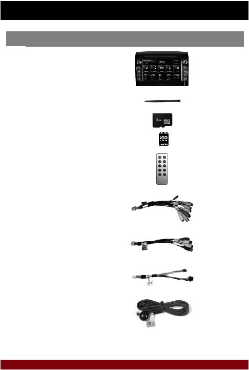
SCOPE OF DELIVERY / Lieferumfang
NO. |
ITEM |
FIGURE |
QUANTITY |
Nr. |
Artikel |
Abbildung |
Anzahl |
|
|
|
|
1 |
MAIN DEVICE |
|
1 |
Hauptgerät |
|
||
|
|
|
|
2 |
STYLUS |
|
1 |
Markierstift |
|
||
|
|
|
|
|
MICRO SD CARD 8GB INKL: |
|
|
3 |
NAVIGATION SOFTWARE |
|
1 |
MicroSD Speicherkarte 8GB |
|
||
|
|
|
|
|
Navigationssoftware |
|
|
|
|
|
|
4 |
REMOTE CONTROL |
|
1 |
Fernbedienung |
|
||
|
|
|
|
5 |
G71-AUD0119 |
|
1 |
AUDIO / VIDEO / AV INPUTS |
|
||
|
Audio / Video / AV-Eingänge |
|
|
|
|
|
|
6 |
G71-MNV0010 |
|
1 |
AUDIO OUTPUTS 5.1 WITH REMOTE TURN ON |
|
||
|
Audio-Ausgänge 5.1 mit Einschaltleitung |
|
|
|
|
|
|
7 |
G71-WHE0063 |
|
1 |
VAR. SYSTEM CONNECTIONS, E.G. DAB BOX |
|
||
|
Div. System-Anschlüsse, z.B. DAB-Box |
|
|
|
|
|
|
8 |
G71-MIC0008 |
|
1 |
EXTERNAL BT-MICROPHONE |
|
||
|
Externes BT-Mikrofon |
|
|
|
|
|
|
4

SCOPE OF DELIVERY / Lieferumfang
NO. |
ITEM |
FIGURE |
QUANTITY |
Nr. |
Artikel |
Abbildung |
Anzahl |
|
|
|
|
9 |
G71-CCD0037 |
|
1 |
CAMERA CONNECTIONS |
|
||
|
Kamera-Anschlüsse |
|
|
|
|
|
|
10 |
G71-MNV0009 |
|
1 |
AUDIO/VIDEO OUTPUTS 1/2 |
|
||
|
Audio/Video-Ausgänge |
|
|
|
|
|
|
|
G71-USB0055 |
|
|
11 |
USB PORT 1 & 2 WITH |
|
2 |
QUICK CHARGE FUNCTION |
|
||
|
|
|
|
|
USB-Anschluss 1 & 2 |
|
|
|
mit Schnellldadefunktion |
|
|
|
|
|
|
12 |
GPS ANTENNA |
|
1 |
GPS Antenne |
|
||
|
|
|
|
13 |
TMC WIRE ANTENNA |
|
1 |
TMC Kabelantenne |
|
||
|
|
|
|
|
Y-ANTENNA ADAPTOR WITH 2,5 MM |
|
|
14 |
INPUT-JACK, UNIVERSAL ISO |
|
1 |
CONNECTOR |
|
||
|
|
|
|
|
Y-Antennen Adapter mit 2,5 mm Klinken- |
|
|
|
stecker, Universal ISO Anschluss |
|
|
|
|
|
|
|
G71-WHE0078 |
|
|
15 |
ADAPTOR CANBUS / STEERING |
|
1 |
WHEEL CONTROL |
|
||
|
Adapter CANBUS / Lenkradfernsteuerung |
|
|
|
|
|
|
16 |
MOUNTING HOLDER |
|
2 |
Montage-Rahmen |
|
||
|
|
|
|
5

CONNECTION DIAGRAM / Anschlussdiagramm
AUDIO / VIDEO / AV INPUTS |
5 |
|
|
|
6 |
|
AUDIO OUTPUTS 5.1 WITH REMOTE TURN ON |
|||||||||||||||||
Audio / Video / AV-Eingänge |
|
|
|
|
Audio-Ausgänge 5.1 mit Einschaltleitung |
|||||||||||||||||||
|
|
|
|
|
|
|
|
|
|
|
|
|
|
|
|
|
|
|
|
|
|
|
|
|
|
|
|
|
|
|
|
|
|
|
|
|
|
|
|
|
|
|
|
|
|
|
|
|
|
|
|
|
|
|
|
|
|
|
|
|
|
|
|
|
|
|
|
|
|
|
|
|
|
|
|
|
|
|
|
|
|
|
|
|
|
|
|
|
|
|
|
|
|
|
|
|
|
|
|
|
|
|
|
|
|
|
|
|
|
|
|
|
|
|
|
|
|
|
|
|
|
|
|
|
VAR. SYSTEM CONNECTIONS, E.G. DAB BOX |
7 |
|
|
|
|
10 |
AUDIO/VIDEO OUTPUTS 1/2 |
Div. System-Anschlüsse, z.B. DAB-Box |
|
|
|
|
Audio/Video-Ausgänge |
||
EXTERNAL BT-MICROPHONE |
|
|
|
|
CAMERA CONNECTIONS |
||
8 |
9 |
||||||
Externes BT-Mikrofon |
|
|
|
|
Kamera-Anschlüsse |
||
I |
ISO CONNECTOR OF THE VEHICLE |
ISO-Stecker des Fahrzeugs |
|
|
11 |
USB PORT 1 WITH QUICK CHARGE FUNCTION |
|
|
|
USB-Anschluss 1 mit Schnellladefunktion |
|
|
11 |
USB PORT 2 FOR OEM USB-PORT |
|
|
USB-Anschluss 2 für OEM USB-Anschluss |
|
|
|
|
AM/FM ANTENNA |
|
|
|
AM/FM Antenne |
FUSE |
12 |
GPS ANTENNA |
|
Gerätesicherung |
GPS Antenne |
|
6

CONNECTION DIAGRAM / Anschlussdiagramm
I |
ISO ASSIGNMENT |
ISO Belegung |
|||
A4 |
= |
CONSTANT PLUS |
A4 |
= |
Dauerplus |
A5 |
= |
ANTENNA |
A5 |
= |
Antenne |
A6 |
= |
ILLUMINATION |
A6 |
= |
Beleuchtung |
A7 |
= |
IGNITION PLUS |
A7 |
= |
Zündungsplus |
A8 |
= |
GROUND |
A8 |
= |
Masse |
B1 |
= SPEAKER REAR RIGHT + |
B1 |
= |
Lautsprecher hinten rechts + |
|
B2 |
= SPEAKER REAR RIGHT – |
B2 |
= |
Lautsprecher hinten rechts - |
|
B3 |
= SPEAKER FRONT RIGHT + |
B3 |
= |
Lautsprecher vorne rechts + |
|
B4 |
= SPEAKER FRONT RIGHT – |
B4 |
= |
Lautsprecher vorne rechts - |
|
B5 |
= SPEAKER FRONT LEFT + |
B5 |
= |
Lautsprecher vorne links + |
|
B6 |
= SPEAKER FRONT LEFT – |
B6 |
= |
Lautsprecher vorne links - |
|
B7 |
= SPEAKER REAR LEFT + |
B7 |
= |
Lautsprecher hinten links + |
|
B8 |
= SPEAKER REAR LEFT – |
B8 |
= |
Lautsprecher hinten links - |
|
C1 |
= |
KEY1 |
C1 |
= |
Key1 |
C2 |
= |
KEY2 |
C2 |
= |
Key2 |
C3 |
= |
AUX GROUND |
C3 |
= |
AUX Masse |
C7 |
= |
AUX SIGNAL R |
C7 |
= |
AUX Signal R |
C10 |
= |
AUX SIGNAL L |
C10 |
= |
AUX Signal L |
C19 |
= |
CAN LOW |
C19 |
= |
Can Low |
C20 |
= |
CAN HIGH |
C20 |
= |
Can High |
7

CONNECTION DIAGRAM / Anschlussdiagramm
ENGLISH
IMPORTANT NOTE: On vehicles with radio preparation and ISO connectors usually a „Plug and Play“ installation is possible. In this case, it is important that the ESX Naviceiver is connected with the ignition plus (ACC, PIN 7).
ATTENTION: Never use the CANBUS together with ignition plus.
FUSE: In case of a defect, the fuse must be replaced with a fuse of the same value (10A). Eliminate the cause of the short circuit before replacing the defective fuse.
ASSIGNMENT OF THE ACCESSORY CONNECTORS |
|
|
||
5 |
Audio / Video / AV Inputs G71-AUD0119 |
|
|
|
Name |
|
Connector/Color |
Function |
|
AV1-L-IN |
RCA white |
AV Audio left in AV/TV menu |
||
AV1-R-IN |
RCA red |
AV Audio right in AV/TV menu |
||
AV1-V-IN |
RCA yellow |
AV Video in AV/TV menu |
||
AV2/TV-L-IN |
RCA white |
AV2 Audio left in AV/TV menu |
||
AV2/TV-R-IN |
RCA red |
AV2 Audio right in AV/TV menu |
||
AV2/TV-V-IN |
RCA yellow |
AV2 Video in AV/TV menu |
||
AV3/AUX1-L-IN |
RCA white |
AV3 Audio left in AV/TV menu |
||
AV3/AUX1-R-IN |
RCA red |
AV3 Audio right in AV/TV menu |
||
AV3-V-IN/VIDEO |
RCA yellow |
AV3 Video in AV/TV menu |
||
+12V OUT |
yellow |
12V Output |
||
|
|
|
Power supply for external devices such as DVB-T tuners. |
|
|
|
|
Maximum current consumption 500 mA. |
|
GND |
|
plack |
Ground wire to +12V OUT |
|
TV-CONT-OUT |
brown |
Control cable for special ESX devices, please do not use. |
||
BRAKE IN |
pink |
Connect to the parking brake signal to the device. |
||
|
|
|
The cable provides ground when the parking brake is operated. |
|
|
|
|
Please do not use if the CANBUS is used, CANBUS has always priority. |
|
6 |
Audio – Outputs 5.1 with Remote Turn On G71-MNV0010 |
|||
Name |
|
Connector/Color |
Function |
|
FL-OUT |
|
RCA white |
Pre-amplifier output front left |
|
FR-OUT |
|
RCA red |
Pre-amplifier output front right |
|
RL-OUT |
|
RCA white |
Pre-amplifier output rear left |
|
RR-OUT |
RCA red |
Pre-amplifier output rear right |
||
SUBWOOFER-OUT |
RCA brown |
Pre-amplifier output Subwoofer (Mono) |
||
CENTER-OUT |
RCA yellow |
Pre-amplifier output Center (Mono) |
||
AMP-CONT-OUT |
green |
Remote Turn On output |
||
|
|
|
12V output to turn on an external amplifier. |
|
|
|
|
Maximum current consumption 500 mA. |
|
7 |
Various System Connections G71-WHE0063 |
|
|
|
Name |
|
Connector/Color |
Function |
|
Uart/+5V OUT |
black |
Reserved, please do not use! |
||
SWC1IN |
red-white |
For an analog steering wheel signal. Please do not use! |
||
SWC2IN |
green-white |
For an analog steering wheel signal. Please do not use! |
||
ILL IN |
|
orange |
Illumination signal „ILL“ input. Same function as ILL on the ISO plug. |
|
ANT-POWER OUT |
yellow |
12V output for FM antenna amplifiers. Attention! The power supply is only active |
||
|
|
|
while the FM function of the device is activated. Max. Current consumption 100 mA. |
|
8

CONNECTION DIAGRAM / Anschlussdiagramm
9 Camera connections G71-CCD0037 |
|
|
|
Name |
Connector/Color |
Function |
|
CCD-CVBS-IN |
RCA yellow |
Video signal input from the rear camera |
|
FRONT-CCD-IN |
RCA yellow |
Video signal input from the front camera |
|
REVERSE IN |
blue |
Reverse gear signal input. Please don‘t use when vehicle‘s CANBUS is operated. |
|
|
|
If CAN signal is not present, the reverse signal (12V, for example the reversing |
|
|
|
light) can be connected here. The ESX device switches to the „CCD CVBS IN“ |
|
|
|
input as soon as „REVERSE IN“ is supplied with 12V and „CCD-Camera“ |
|
|
|
checkbox in the option menu under „DISPLAY“ is activated. |
|
CCD-POWER OUT |
yellow |
12V power supply output for an aftermarket rear view camera with max. |
|
|
|
100mA. 12V will be supplied, as soon as „REVERSE-IN“ is supplied with 12V. |
|
FRONT CCD-POWER OUT |
red |
12V power supply output for an aftermarket rear view camera with max. |
|
|
|
500mA. 12V will be supplied, as soon as the ESX device is turned on. |
|
|
|
Make sure that your camera is suitable for continuous operation. |
|
GND |
black |
Ground terminal of the power supply of an optional camera (front and rear). |
|
Connect the reverse signal (12V when reverse gear is engaged, for example, also by reversing light) of the vehicle to „REVERSE“ (blue cable). The „GND“ and „CCD POWER OUT“ cables must not be connected mandatory, but can be used as a power supply for the camera.
Now activate the „CCD-Camera“ checkbox under APPS -> OPTIONS -> DISPLAY at the ESX device.
Operation note:
-Special feature: Push the right rotary controller to display the rear view cam, even when the reverse gear is not engaged.
-When the reverse gear is engaged, the device does not allow any other operation, all the buttons and controllers except volume controller are blocked for security reasons. If the device is switched off and the reverse gear is engaged, the device does not even turn on.
Installation note with original OEM camera for type 290 Model: If the CANBUS cable set „VNA-DUC-CAN-SET“ (See page 3) is used, only the yellow RCA plug „CCD CVBS IN“ must be connected. All other signals are taken over by the CANBUS.
FRONT VIEW CAMERA
Connect the camera via RCA to the yellow RCA connector „FRONT CCD IN“.
Switch to „Camera“ or „Front Camera“ in the menu „AV/TV“ to display your camera view.
10 Audio/Video Outputs G71-MNV0009
Name |
Connector/Color |
AUDIO L OUT/ZONE-1 |
RCA white |
AUDIO R OUT/ZONE-1 |
RCA red |
V-OUT1/ZONE-1 |
RCA yellow |
AUDIO L OUT/ZONE-2 |
RCA white |
AUDIO R OUT/ZONE-2 |
RCA red |
V-OUT2/ZONE-2 |
RCA yellow |
IMPORTANT NOTE: Connection for e.g. headrest monitors or other devices such like TVs in the rear. The audio/video outputs is always the same signal to which will be played just on the ESX device. An independent input source selection is not possible.
9
 Loading...