

Page 1

High Capacity
Axial Fan
Evaporative Cooler
Model Series
FAD242
FAD248
Circle the model of your cooler and record
the serial number below .
Encierre con un circulo el modelo de su
enfriador y escribe el número de serie
abajo.
Read Carefully All Of This Manual Before
Installing The Unit
Serial #
Número de Serie
Table Of Contents
Safety Instructions ......................................................................... 1
Operation........................................................................................ 1
Installation Instructions .................................................................. 2
Maintenance Section....................................................................2-3
Electrical Wiring Diagrams.............................................................. 3
Troubleshooting.............................................................................. 4
Read And Save These Instructions
Safety Rules
1. Read instructions carefully.
2. Disconnect all electrical service that will be used for the unit before
you begin the installation.
3. Electrical hook up should be done by a qualified electrician, so that
all electrical wiring will conform to your local standards.
4. For a maximum safety precaution, make sure cooler cabinet is
properly grounded to a suitable ground connection.
5. Cooler must be connected to proper line current, voltage and cycle,
as stamped on cooler motor and pump motor specification plate.
Lea Con Cuidado Todo Este Manual Antes De
Instalar La Unidad
Warranty ......................................................................................... 4
General Specifications (Especificaciones Generales) ..................... 5
Motor Specifications (Especificaciones Del Motor)....................... 5
Parts List - Blower Section (Lista De Piezas) ............................ 6-7
Parts List - Wet Section (Lista De Piezas) .................................. 8-9
Spanish (Instrucciones en Español)...........................................9-12
6. This unit must be installed at a height of 10 feet or greater from the
floor.
7. Always Disconnect Power before performing any maintenance.
Operation
T o eliminate delivery of hot air when starting cooler , Start the pump
without the blower for the first few minutes, then turn on the blower
motor.
These coolers may be used without water for ventilation purposes.
When outside air is cool (for example, at night) or when humidity is
high the water pump can be turned off.
110497 12-09
Page 2

Installation
CAUTION: Make sure that the mounting surface is strong
enough to support the operating weight of the cooler when in
use. (For operating weight, see Specification Table.)
CAUTION: Never start cooler until installation is complete
and unit has been tested for rigidity.
CAUTION: This unit must be installed at a height of 10 feet
or greater from the floor.
Electrical Installation
NOTE: Local building code regulations must be observed.
WARNING: Disconnect all electrical service that will be
used for this unit before you begin the installation.
• Connect electrical. Cooler must be connected to the proper line
current, voltage and cycle, as indicated on the decal located at the
electrical service entrance. Connecting improper voltage to motor
will void motor warranty. See the wiring diagrams (figures 8 & 9)
on page 3 for wiring electrical connections.
NOTE: A separate 120 Volt, 60 Hz, 1 phase pump electrical circuit
is required to maintain the integrity of the GFCI pump protection
and to maintain the U.L. Listing of the evaporative cooler.
• Wire gage. The horse power, voltage, cycle, phase, current, and
length of wire required from switch to motor will determine the
gauge of wire to be used.
• Switches. Larger horsepower and three phase applications require
switches (not supplied) of proper current capacity and should be
installed by a competent electrician.
• Power Supply box. The
power supply box is located in the upper inside
of the divider channel.
Remove the cover to access wiring. (Fig. 1).
Connect wiring in box to
power supply wiring as
per wiring diagrams.
WARNING: Make sure that cooler cabinet is properly
grounded to a suitable ground connection for maximum safety.
Water Connection
• Pumps. Plug the pumps into the pump receptacles. There are
metal cord retaining clips on the corner post and motor cross braces
for retaining the pump cords.
CAUTION: The pump cord must be secured to prevent it
from dropping into water reservoirs or contacting moving components.
• Install overflow assembly. Remove
nut and place nipple through the hole
in the pan, with the rubber washer
between the pan and the head of the
drain nipple (Fig. 2). Screw on nut
and draw up tight against bottom of
pan. Insert overflow pipe in nipple
to retain water. Overflow pipe may
be removed to drain pan when necessary. A garden hose may be screwed on the drain nipple to drain
water away from your unit.
Power
Supply
Box
Fig. 1
Overflow Pipe
Nipple
Rubber Washer
Bottom Pan
Nut
Fig. 2
Cover
• Connect water supply line. A water supply line should be run to
the cooler to supply an adequate amount of cold water to the unit.
The amount of water each cooler uses will depend on the weather
conditions in your area and the size of your unit. The hotter and
dryer your climate and the higher the capacity of your unit, the
more water will evaporate. For example: An FAD248 unit with a
2 hp motor will use approximately 85 gallons per hour in a hot and
dry climate like Las V egas on a 105°F day with 10% humidity . The
same unit in a cooler climate with 95°F and 20% humidity would
use approximately 63 gph.
NOTE: Do not connect the water supply line to any soft water
applications.
• Install float valve and fill pan. Refer to Fig. 3. Remove items 1,
2, 3, and 4. Insert float body (5) through hole in back post panel as
shown. Install washer (1) and nut
(2). Tighten to keep float from
turning. Place nut (4) and ferrule
(3) on water supply line. Con-
5
4
3
2
1
nect to float fitting and tighten until
water tight. Loosen screw (6) and
adjust rod (7) until water level is
7
6
8
within 1" of top of reservoir.
Tighten screw (6). Slide float
shield (8) up over float body (5)
Fig. 3
until it snaps into place.
• Bleed-Off. Use of the bleed-off kit is recommended to prevent
scale build up by bleeding off small amounts of circulating water
during operation. Do not add any type of water treatment chemicals to the water.
Maintenance
WARNING: Before doing any maintenance be sure to dis-
connect from power source. This is for your safety.
Spring Start-Up
• Check belt tension. A 3 lb. force
should deflect the belt 3/4 inches
(see Fig. 4). Readjust belt if
needed.
To adjust belt, loosen the two
hinge nuts and the locking nut on
the adjusting bolt as shown in
figure 5. Loosen or tighten the
adjustment nut until the belt is
at the right tension. Lock the
motor plate in place by tightening the locking nut and then
tighten the 2 hinge nuts.
• Grease bearings. The shaft
bearings in this unit should be
greased once a year with a good
grade of ball bearing grease.
• Clean pads. A clean pad is more absorbent, efficient and will give
more cool air. Annually , or when required, using a garden hose with
nozzle, back wash to clean out the openings, then clean off the inlet
face any scale or other obstruction to the passages. Slight scraping
may be required to remove hardened scale.
Hinge
Nut
Hinge
Nut
3 Lb.
3/4 Inches
Fig. 4
Adjustment Nut
Lock-Nut
Fig. 5
2
1 10497
Page 3

• Pad replacement. The pads should be replaced after 5 years or
before if necessary. To change pads, remove top access panel,
remove grill, and disconnect water delivery tube. Remove water
distributor holder and lift out media sections. Replace with the
same type media. You can purchase them from your dealer.
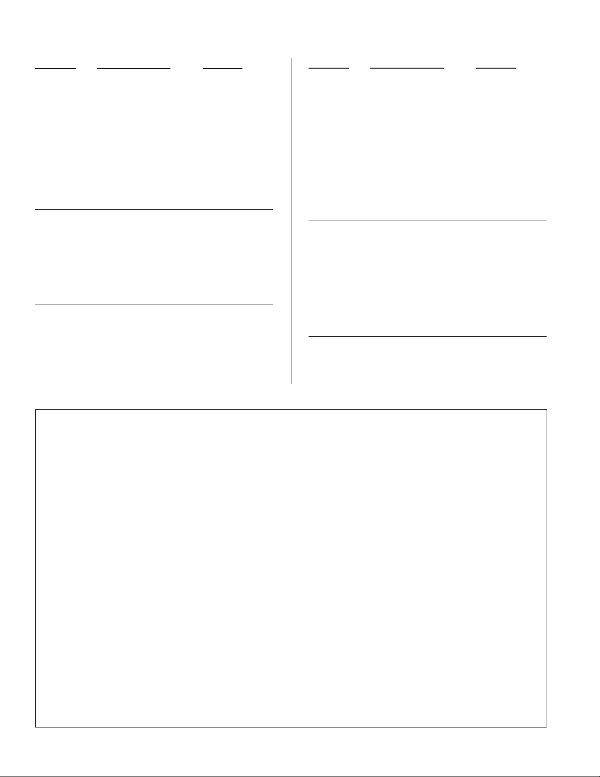
IMPORTANT: In order to get the best performance from your
cooling pads, they must be installed properly. If you have purchased a pad with two equal angles, the following instructions can
be disregarded. Pads must always be installed with the steeper
flute angle sloping down towards the air entering side (Fig. 6). The
reason is simple. The
steeper angle puts more
water on the hot, dry, dirty
side of the pad where it is
needed most. It also coun-
Entering
Air
45°
Leaving Air
teracts the tendency of the
air to push the water toward the back of the pad.
Fig. 6
15°
• Cleaning pumps. Cleaning the
pumps is necessary once a year at
start-up. For your safety, discon-
Remove
nect from power source and unplug
pump. Remove the pump from
the mount bracket. Remove the
base of the pump (Fig. 7). Clean
the pump and turn the impeller to
ensure free operation. Remove the
Fig. 7
pump spout and check for any blockage. After cleaning, reinstall
the base onto the pump. Reattach the pump to the mount in the
cooler to ensure that the pump will not overturn. Do not forget to
replace the spout and water delivery tube onto the pump outlet.
NOTE: The pump has automatic reset thermal protection. The
pump motor will stop if it overheats. The pump will operate
normal again after obstruction is cleared.
• Check bleed-off valve to be sure it is not clogged.
Winter Shut Down
• Drain water. Always drain all of the water out of the cooler and
water supply line when not in use for prolonged periods, and particularly at the end of the season. Keep the water line disconnected
from both the unit and water supply so that water will not seep
into the line and freeze.
• Disconnect from power supply when not in use for extended
periods of time.
• Cover unit. To protect the life of the finish, a cover for the unit is
suggested in extended periods of non use.
By following the operating, installation, and maintenance suggestions
as outlined, you can get many years of efficient and satisfactory
service from your cooler. In the event additional information is desired, your dealer will be more than glad to assist you in every possible
way.
Fan
Motor
Pumps
Fan
Motor
Pumps
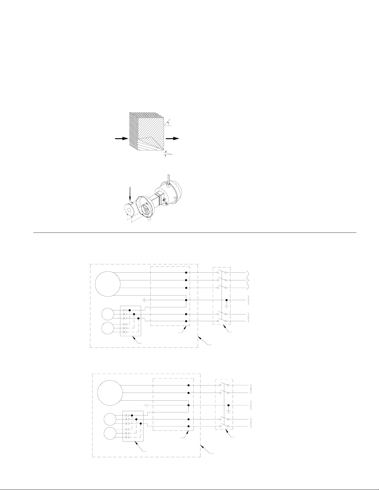
Wiring Diagrams
For 1 or 2 HP , 1 Phase Motor
Black
White
Green
Green
Blue
White w/ Stripe
Installation
Wiring Box
GFCI Receptacle
Fig. 8
For 1 or 2 HP , 3 Phase Motor
Black
White
Red
Green
Green
Blue
White w/ Stripe
Installation
Wiring Box
GFCI Receptacle
L1
N
L1
N
Required Service Disconnect
In Sight Of Unit
Unit Cabinet
L1
L2
L3
L1
N
Required Service Disconnect In
Sight Of Unit
Unit Cabinet
120V - 60Hz - 1PH
Or 240V
Equipment
Ground
120V - 60Hz - 1PH
(Separate Circuit)
240V - 60Hz - 3PH
Or 460V
Equipment
Ground
120V - 60Hz - 1PH
Separate Circuit
1 10497
Fig. 9
3
Page 4
Troubleshooting Guide
Problem Possible Cause Remedy
Failure to
start or no
air delivery
Inadequate
air delivery
with cooler
running
Motor
cycles on
and off
1. No electrical power to
unit
• Fuse blown
• Circuit breaker
tripped
2. Belt too loose or tight
3. Motor overheated
• Belt too tight
• Blower bearings dry
4. Motor locked
1. Insufficient air exhaust
2. Belt too loose
3. Pads plugged
4. Insufficient water
flow over pads
1. Low voltage
2. Excessive belt tension
3. Fan shaft tight or
locked
4. Bearings dry
5. Faulty motor
1. Check power
• Replace fuse
• Reset breaker
2. Adjust belt tension
3. Determine cause of
overheating
• Adjust belt tension
• Grease blower
bearings
4. Replace motor
1. Open windows or
doors to increase air
flow
2. Adjust belt tension
or replace if needed
3. Clean pads
4. Clean distribution
system
1. Check voltage
2. Adjust belt tension
3. Grease or replace
bearings (Disconnect
unit)
4. Grease bearings
5. Replace motor
Problem Possible Cause Remedy
Musty or
unpleasant
odor
Noisy
Inadequate
cooling
Excessive
humidity
in building
1. Stale or stagnate water
in cooler
2. Pads not wetting
properly
• Dist. tube holes
clogged
• Pump not working
properly
• Insufficient water
flow over pads
1. Bearings dry
2. Loose parts
1. Inadequate exhaust in
building
2. Pads not wet
• Pads plugged
• Dist. tube holes
clogged
• Pump not working
properly
1. Inadequate exhaust
1. Drain pan and clean
pads
2. Check water
distribution system
• Clean
• Replace or clean
pump (Unplug)
• Clean water
distribution system
1. Grease bearings
2. Tighten loose parts
1. Open windows or
doors to increase air
flow
2. Check water
distribution system
• Clean pads
• Clean
• Replace or clean
pump (Unplug)
1. Open doors or
windows
Limited W arranty
This warranty is extended to the original purchaser of an evaporative cooler installed and used under normal conditions. It does not cover
damages incurred through accident, neglect, or abuse by the owner. We do not authorize any person or representative to assume for us any
other or different liability in connection with this product.
Terms And Conditions Of Warranty
Lifetime Limited Coverage on water reservoir against any leakage due to defects in material. From date of purchase, if any original
component part fails due to defect in material or factory workmanship only, we will provide the replacement part as follows:
One year on the cabinet components.
Two years on the evaporative media.
Exclusions From The Warranty
W e are not responsible for any incidental or consequential damage resulting from any malfunction.
W e are not responsible for any damage received from the use of water softeners, chemicals, descale material, plastic wrap, or if a motor of
a higher horsepower than what is shown on the serial plate is used in the unit.
W e are not responsible for the cost of service calls to diagnose cause of trouble, or labor char ge to repair and/or replace parts.
How To Obtain Service Under This Warranty
Contact the Dealer where you purchased the evaporative cooler. If for any reason you are not satisfied with the response from the dealer,
contact the Customer Service Department: 5800 Murray Street, Little Rock, Arkansas 72209. 1-800-643-8341. E-mail:
info@championcooler.com, W eb: www .championcooler .com.
This limited warranty applies to original purchaser only
4
1 10497
Page 5

General Specifications / Especificaciones Generales
*Weight (lbs.)
Model Series
Serie de Modelo
Peso (l i b ras)
Dry
Seco
Operating
Lleno
FAD242 761 1041 42
FA D248 789 1069 52
Height
Altura
Ca bine t Dime nsio ns (in .)
Dimensiones De La Caja (pulgadas)
Width
Anchura
1
/
8
1
/
8
97 1/
97 1/
4
4
Depth
Profundidad
60 1/
60 1/
Duct Opening (in.)
Abertura De Ducto (pulgadas)
Width
Anchura
4
4
46 46
52 52
*T he w eight inc lud e s a 2 H P mo tor. / El peso to ta l incluye el peso de un motor de 2 C .V.
Motor Specifications / Especificaciones Del Motor
Model
Modelo
FAD2 42 B 111 1104 57 1 1 115 5/ 8 1103 16 11 0 2 12 (4 L57 0)
FAD242B112 110457 1 1 208- 2 30 5/8 110316 110212 (4L5 70)
FAD242B132 110462-1 1 3 208-230 5/8 110316 110212 (4L570)
FAD242B134 110462-1 1 3 460 5/8 110316 110212 (4L570)
FAD242B211 11 0483 2 1 115 5/8 110317 110227 (4L580)
FAD242B212 110483 2 1 208- 230 5/8 110317 110227 (4L580)
FAD242B232 110464-1 2 3 208-230 5/8 110317 110227 (4L580)
FAD242B234 110464-1 2 3 460 5/8 110317 110227 (4L580)
FAD248B211 11 0483 2 1 115 5/8 110317 110227 (4L580)
FAD248B212 110483 2 1 208- 230 5/8 110317 110227 (4L580)
FAD248B232 110464-1 2 3 208-230 5/8 110317 110227 (4L580)
FAD248B234 110464-1 2 3 460 5/8 110317 110227 (4L580)
NOTE: All motors are single speed. For more information on motors contact your dealer. /
NOTA: Todos los mot ores son de una velocidad. Si desea más información establece contact o con su com ercian te.
Motor
Motor
HP
C.V.
Phase
Fase
Volts
Voltios
Shaft (in.)
Eje (pulgadas)
Motor Pulley
Polea De Motor
Drive B elt
Correa
Height
Altura
1 10497
5
Page 6

Replacement Parts Drawing / Dibujo De Piezas De Repuesto
F AD242B, F AD248B
20
19
20
4
1
27
28
26
25
24
23
21
12
8R
22
14
10
11
15
16
13
9
13
3L
19
18
3R
18
19
8L
17
6
5
2
7L
18
7R
6
1 10497
Page 7

Replacement Parts List / Lista De Piezas De Repuesto
All parts may be ordered from your dealer, but not directly from the factory . Be sure that you furnish the following information on all orders. / T odas
las partes pueden ser pedidas con su concesionario, pero no directamente a la fábrica. Incluya toda la información siguiente con su pedido:
1. Cooler serial number / Número de serie de la unidad
2. Description and part number / Descripción y número de parte
3. Cooler size / Tamaño de la unidad
4. Date of purchase / Fecha de compra
Failure to supply all of this information will delay your order. / El no proporcionar toda esta información resultará en una demora.
No.
N° Description / Descripción FAD242B FAD248B
1. Top, Cabinet / Tapa De La Caja ---------------------------------------------------------------------------- 216117-003 216117-003
2. Bottom, Cabinet / Base De La Caja ------------------------------------------------------------------------ 316117-008 316117-012
3R. Corner Post, Right / Poste De Esquina, Derecha --------------------------------------------------------- 318117-026 318117-033
3L. Corner Post, Left / Poste De Esquina, Izquierda ---------------------------------------------------------- 318117-027 318117-032
4. Divider Channel / Panel Divisora --------------------------------------------------------------------------- 218117-028 218117-034
5. Venturi Plate / Venturi ----------------------------------------------------------------------------------------- 216117-011 216117-015
6. Fan Blade / Palas del V entilador ----------------------------------------------------------------------------- 110841 110842
7R. Bottom Connect Bracket, Right / Abrazadera Del Conectar De Abajo, Derecha -------------------- 214109-004 214109-008
7L. Bottom Connect Bracket, Left / Abrazadera Del Conectar De Abajo, Izquierda -------------------- 214109-011 214109-010
8R. Drive Channel, Right / Soporte Para El Sistema De Transmisión, Der echa--------------------------- 214109-005 214109-005
8L. Drive Channel, Left / Soporte Para El Sistema De Transmisión, Izquierda --------------------------- 214109-003 214109-003
9. Bearing Mount / Soporte Para Los Cojinetes-------------------------------------------------------------- 214109-009 214109-009
10. Motor Mount / Montura Del Motor ------------------------------------------------------------------------ 314109-006 314109-006
11. Motor Mount Adjustment Plate / Placa Ajustable Del Montura Del Motor ------------------------- 214109-007 214109-007
12. Belt Ajustment Support Angle / Ángulo De Soporte Para Ajustar El Correa------------------------- 211101-001 211101-001
13. Bearings, Fan Blade / Cojinetes Del Eje Del Ventilador--------------------------------------------------- 110355 110355
14. Drive Belt / Correa-------------------------------------------------------------------------------------------- **
15. Pulley, Fan / Polea Del V entilador--------------------------------------------------------------------------- 110282 110282
16. Shaft, Fan / Eje Del Ventilador ------------------------------------------------------------------------------- 110156 110156
17. Front Panel / Panel Del Frente------------------------------------------------------------------------------- 318117-024 318117-030
18. Connect Bracket / Abrazadera Del Conectar -------------------------------------------------------------- 214120-001 214120-001
19. Lift Bracket / Soporte De Levantamiento ------------------------------------------------------------------ 212101-001 212101-001
20. Inspection Panel / Panel De Inspección -------------------------------------------------------------------- 220116-008 220116-009
21. Motor / Motor ------------------------------------------------------------------------------------------------- **
22. Pulley, Motor / Polea Del Motor ---------------------------------------------------------------------------- **
23. Electrical Conduit / Conducto Eléctrico--------------------------------------------------------------------- 110816 110816
24. Pump Receptacle Box And Cover / Caja De Empalme Y Cubierta Para Las Bombas --------------- 110821 110821
25. GFCI Receptacle / Receptáculo GFCI ---------------------------------------------------------------------- 110818 110818
26. Liquid Tight Non-Metalic connector / Conector Estanco De No Metálico ---------------------------- 110817 110817
27. Power Supply Box / Caja De Empalme Principal -------------------------------------------------------- 110815 110815
28. Cover, Power Supply Box / Cubierta De La Caja De Empalme---------------------------------------- 110815-1 110815-1
* See motor specification table. / Vea la tabla de especificaciones del motor .
NOTE: Standard hardware items may be purchased from your local hardware store.
NOT A: Artículos de uso corriente pueden comprarse en la ferr etería de su localidad.
1 10497
7
Page 8

Replacement Parts Drawing / Dibujo De Piezas De Repuesto
F AD242W8, F AD248W8
9
14R
15
13R
10
11
1
21
4
5
6
12
8
7
3
2
19
20
17
16
18
8
1 10497
Page 9

Replacement Parts List / Lista De Piezas De Repuesto
All parts may be ordered from your dealer, but not directly from the factory. Be sure that you furnish the following information on all orders. /
T odas las partes pueden ser pedidas con su concesionario, per o no dir ectamente a la fábrica. Incluya toda la información siguiente con su pedido:
1. Cooler serial number / Número de serie de la unidad
2. Description and part number / Descripción y número de parte
3. Cooler size / Tamaño de la unidad
4. Date of purchase / Fecha de compra
Failure to supply all of this information will delay your order. / El no proporcionar toda esta información resultará en una demora.
No.
N° Description / Descripción FAD242W8 FAD248W8
1. Top Access Panel / Panel Superior De Acceso ------------------------------------------------------------------ 218116-030 218116-030
2. Bottom, Cabinet / Base De La Caja ------------------------------------------------------------------------------ 218116-031 218116-031
3. Side Panel, Right / Panel Del Lado, Derecha -------------------------------------------------------------------- 318116-028 318116-047
4. Side Panel, Left / Panel Del Lado, Izquierda -------------------------------------------------------------------- 318116-027 318116-046
5. Float V alve / Flotador ----------------------------------------------------------------------------------------------- FL 3/8 FL 3/8
6. Support, Media / Soporte Para El Medio Evaporativo -------------------------------------------------------- 218116-029 218116-029
7. Over Flow Assembly / Montaje De Desagüe -------------------------------------------------------------------- 3OA-2 3OA-2
8. W ater Reservoir / Bandeja Acumuladora De Agua-------------------------------------------------------------- 281036 281036
9. Perforated Panel / Parrilla Perforada----------------------------------------------------------------------------- 218126-005 218126-006
10. Evaporative Media / Medio Evaporativo------------------------------------------------------------------------- 110115 110116
11. Media Shield / Pantalla Protectora Para El Medio Evaporativo---------------------------------------------- 281026-011 281026-012
12. Float Shield / Pantalla Protectora Del Flotador ----------------------------------------------------------------- 281005-001 281005-001
13R. Water Distributor Assembly , Right (Shown) / Sistema Del Distribuidor De Agua, Derecho (Mostrado) ---------- 3D-28R 3D-28R
13L. Water Distributor Assembly, Left / Sistema Del Distribuidor De Agua, Izquierdo ------------------------ 3D-28L 3D-28L
14R. W a t e r D i s t r i b u t or H o u s i n g , R i g h t ( S h own) / Caja Del Distribuidor De Agua, Der echo (Mostrado) -------------- 322140-043 322140-043
14L. Water Distributor Housing, Left / Caja Del Distribuidor De Agua, Izquierdo ------------------------------ 322140-039 322140-039
15. Water Distributor Tube Clamp / Abrazadera De Tubo Del Distribuidor De Agua ------------------------- 110591 110591
16. Pump Mount / Montura De La Bomba -------------------------------------------------------------------------- 218122-004 218122-004
17. Pump Assembly / Bomba ------------------------------------------------------------------------------------------ 110467 110467
18. Pump Screen / Malla Para La Bomba ---------------------------------------------------------------------------- 281001-001 281001-001
19. T ube, Water Delivery / Tubo De Agua---------------------------------------------------------------------------- 110717 110717
20. Bleed-Off Kit / Equipo De La Válvula De Desahogo ---------------------------------------------------------- 310587 310587
21. Polyester Pad / Filtro De Poliester -------------------------------------------------------------------------------- 110119-4 110119-4
Lea y Conserve Estas instrucciones
Reglas De Seguridad
1. Lea las instrucciones con cuidado.
2. Desconecte todos los servicios eléctricos que serán usados en esta
unidad antes de instalar el enfriador.
3. Las conexiones eléctricas deben ser hechas por un electricista competente, para que todo el cableado eléctrico cumpla con los requisitos
establecidos en su localidad.
4. Para una máxima y segura precaución, debe estar muy seguro que la
caja del enfriador está conectada con la tierra.
5. El enfriador debe ser conectado con el propio voltaje, corriente alterna y ciclos, lo que se encuentran en la placa de especificaciones de la
bomba y del motor.
1 10497
6. Debe instalar la unidad a lo menos de 10 pies arriba del piso.
7. Siempre CORTE LA CORRIENTE antes de realizar cualquier labor
de mantenimiento.
Operación
Para que no salga aire caliente al principio, prenda sólo la bomba durante
unos cuantos minutos; luego prenda también el motor del ventilador.
Su enfriador puede ser utilizado sin agua para proporcionar ventilación
solamente. Cuando esté fresco (por ejemplo, de noche) o cuando la
humedad es alta, la bomba de agua puede ser apagada.
9
Page 10

Instalación
PRECAUCION: La superficie en que ha de colocarse el
enfriador deberá aguantar el peso completo de la unidad cuando
ésta está en funcionamiento. (Para saber este peso, vea la tabla
de especificaciones.)
PRECAUCION: No conecte el enfriador hasta que la insta-
lación esté completa y se haya comprobado la estabilidad del
mismo.
PRECAUCION: Instale esta unidad a una altura de 10 pies
o más alto del piso.
• Conecte el tubo de abastecimiento de agua. Instale una línea de
abastecimiento de agua para proveer una cantidad adecuada de agua fría
al unidad. La cantidad de agua que utiliza el enfriador dependerá en las
condiciones del tiempo y el tamaño de su unidad. El más caliente y
seca su clima y cuanto mayor es la capacidad de su unidad, más el agua
se evaporará. Por Ejemplo: Un unidad FAD248 con un motor de 2
c.v. utilizará aproximadamente 85 galones de agua por hora en un
clima caliente y seco como Las V egas con 105°F y humedad del 10%.
La misma unidad en un clima más fresco con 95°F y humedad del 20%
utilizaría aproximadamente 63 galones por hora.
NOTA: No conecte el abastecimiento de agua con ninguna aplicación
de agua blanda.
Instalación Eléctrica
NOTA: Los códigos locales de construcción deben ser observadas.
ADVERTENCIA: Desconecte todos los servicios eléctricos
que serán usados en esta unidad antes de instalar el enfriador.
• Conexión eléctrica. El enfriador debe ser conectado con el propio
voltaje, corriente de línea y ciclos, que se encuentran en la placa de
especificaciones de la bomba y del motor. El conectar con el voltaje
incorrecto anulará la garantía del motor. Vea las esquemas de cableado
(las figuras 8 y 9) para conexiones eléctricas.
NOTA: Un circuito separado para las bombas de 120V, 60Hz., y 1 fase
se requiere para mantener la protección de GFCI, y mantener el listado
de U.L. del enfriador evaporativo.
• Calibre de cable. El caballo de valor, voltaje, ciclos, fase, corriente,
número de velocidad para el motor, y largo de cable determinará el
calibre de cable que debe ser usado.
• Interruptores. Aplicaciones trifásicas de más caballo de valor se
requieren unos controles de propia capacidad de corriente y deben ser
instalados por un electricista competente.
• La caja de empalme. La
caja de empalme se encuentra en el poste divisor en la parte superior del
interior del enfriador.
Quite la cubierta para tener acceso al cableado (fig.
1). Conecte el cableado
en la caja al suministro
eléctrico según las
diagramas eléctricas.
ADVERTENCIA: Compruebe que la caja del enfriador tenga
la debida conexión a tierra para proveer máxima seguridad.
Caja De
Empalme
Cubierta
Fig. 1
• Instale la válvula del flotador y llene la bandeja con agua.
Véase la figura 3. Remueva las partes 1, 2, 3 y 4. Inserte el cuerpo del
flotador (5) por el agujero en el poste trasero según lo indicado. Instale la arandela (1) y la tuerca (2). Apriete la tuerca para que el
flotador no dé vuelta. Ponga la tuerca (4) y la férula (3) en la línea de
abastecimiento de agua. Conecte la
línea al flotador y apriete la tuerca
hasta que no salga agua. Afloje el
tornillo (6) y ajuste la varilla (7)
hasta que el nivel del agua esté a una
altura de 1 pulgada por debajo del
borde superior de la bandeja. Apriete el tornillo (6). Ponga la pantalla
protectora del flotador (8) sobre el
cuerpo del flotador hasta que se agarre.
• Instale la válvula de desahogo. Recomendamos usar la válvula de
desahogo para prevenir la formación de escama, por la segregación de
pequeñas cantidades de agua durante la operación. No agregue ningún
tipo de productos químicos del tratamiento de agua al agua.
5
7
6
8
Fig. 3
4
3
2
1
Mantenimiento
ADVERTENCIA: Antes de hacer cualquier mantenimiento,
compruebe que la corriente esté desconectada. Esto es por su
seguridad.
Puesta En Marcha En La Primavera
• Compruebe la tensión de la correa. Una fuerza de 3 libras debe
desviar la correa 3/4 pulgadas (véase fig. 4). Ajuste la correa si es
necesario.
3 Libras
3/4 Pulgadas
Conectar El Agua
• Las Bombas. Enchufe las bombas en los receptáculos de las bombas.
Hay clips de retención para asegurar el cable de la bomba en el poste de
esquina y en el travesaño de la montura del motor.
ADVERTENCIA: El cable de la bomba se debe asegurar
para evitar que caiga en el agua o entre en contacto con piezas
móviles.
• Instale el montaje de desagüe. Quite la tuerca y pase la boquilla
por el agujero de la bandeja, colocando la arandela de goma entre la
bandeja y la cabeza de la boquilla (véase fig. 2). Coloque la tuerca en la
boquilla y atorníllela hasta que quede
apretada contra la parte inferior de la
bandeja. Inserte el tubo de desagüe en
la boquilla para retener el agua. El
tubo de desagüe se puede quitar para
desaguar el agua de la bandeja cuando
sea necesario. Se puede conectar una
manguera de jardín a la boquilla para
desaguar el agua hacia otra parte.
10
Tubo De Desagüe
Boquilla Roscada
Arandela De Goma
Bandeja
Tuerca
Fig. 2
Para ajustar la correa, afloje las dos
tuercas de la bisagra y la tuerca
de fijación en el perno de ajuste
según lo demostrado en la figura
5. Afloje o apriete la tuerca de
ajuste hasta que la correa está en
la tensión correcta. Trabe la placa del motor en lugar apretando
la tuerca de fijación y después
apriete las 2 tuercas de la bisagra.
• Engrasar los cojinetes. Debe
engrasar los cojinetes del eje una
vez al año con un buen grado de
grasa para los cojinetes.
• Limpie el medio evaporativo. Un filtro limpio es más absorbente y
eficiente y producirá un mayor volumen de aire frío. Cada año o
cuando sea necesario, limpie con una manguera de jardín las aberturas.
Tuerca De Fijación
Tuerca
De La
Bisagra
Tuerca
De La
Bisagra
Fig. 4
Tuerca De Ajuste
Fig. 5
1 10497
Page 11
Luego limpie el lado de adentro de cualquier escama u otra obstrucción
a las aberturas. Si requiere, raspe ligeramente para remover escama
endurecida.
• Cambie el medio evaporativo después de 5 años o cuando sea
necessario. Cambiar el medio evaporativo, remueva el panel superior de acceso, remueva la parrilla y desconecte el tubo del distribuidor
de agua. Quite la caja del distribuidor de agua y saque los el medio
evaporativo. Reemplace con los filtros de mismo tipo lo que puede
encontrar con su comerciante.
IMPORTANTE: Para que el enfriador funcione lo mejor, debe instalar
el medio evaporativo correctamente. Si usted ha comprado filtros con
dos ángulos iguales, las instrucciones siguientes no serán provechosas
para usted. Los filtros deben
ser instalados con el ángulo
más escarpado
inclinándose por la entrada del
aire (véase fig. 6). La razón
Entrada
Del Aire
45°
Salida
Del Aire
es que el ángulo más escarpado le ayuda a poner más agua
en el lado seco y caliente donde lo necesita más. También
le ayuda a contrarrestar la ten-
Fig. 6
15°
dencia del aire a empujar el agua
hasta atrás de los filtros.
Remueve
• Limpie la bomba. Es necesario
limpiar la bomba una vez al principio de cada año. Por su propia
seguridad, apague la unidad y desconecte el motor y la bomba.
Quite la bomba de su montura.
Fig. 7
Quite la base de la bomba (véase fig. 7). Limpie la bomba. Dé le vuelta
a la hélice para verificar que se mueve libremente. Quite el pico de la
bomba y vea si está obstruido. Vuelva a colocar la base de la bomba.
Coloque la bomba en la unidad y fíjela en su montura. Esto impedirá
que se caiga la bomba al agua, lo que dañaría el motor. No se olvide de
volver a conectar el tubo de agua a la bomba. La bomba contiene un
depósito protector en caso de sobrecalentamiento (se apagará automáticamente).
• Compruebe la válvula de desahogo para verificar que no esté
obstruida.
Preparar La Unidad Para El Invierno
• Drene el agua. Drene siempre toda el agua de la unidad y del tubo de
abastecimiento de agua cuando no use el enfriador durante períodos
prolongados, especialmente al fin de la temporada. El tubo debe
quedarse desconectado del enfriador y del abastecimiento de agua para
que no lo congele.
• Desconecte de la electricidad cuando no se utiliza el enfriador
por períodos extendidos.
• Cubra la unidad. Para proteger y alargar la vida útil del acabado, se
sugiere cubrir el aparato durante períodos largos cuando no sea utilizado.
Si usted sigue estas sugerencias en cuanto a instalación, operación y
mantenimiento, podrá disfrutar de muchos años de servicio eficiente y
satisfactorio de este enfriador. Si desea más información, su concesionario tendrá mucho gusto en ayudarle con respecto a cualquier duda o
pregunta.
1 10497
Motor
Del
Ventilador
Bombas
Motor
De
Ventilador
Bombas
Esquemas Del Cableado
Para 1 o 2 C.V ., Motor De Una Fase
Negro
Blanco
Rojo
Verde
Verde
Azul
Blanco Con Raya
Caja De
Empalme
Receptáculo GFCI
Fig. 8
Para 1 o 2 C.V ., Motor T rifásico
Negro
Blanco
Verde
Verde
Azul
Blanco Con Raya
Caja De
Empalme
Receptáculo GFCI
Caja Del
Enfriador
Caja Del Enfriador
Fig. 9
L1
240V - 60 Hz - Trifásico
L2
O 460V
L3
Tierra
L1
120V - 60Hz - 1 Fase
N
(Circuito Distinto)
Desconector Requerido Situado
Dentro De La Vista Del Enfriador
L1
L1
120V - 60Hz - 1 Fase
N
O 240V
Tierra
120V - 60Hz - 1 Fase
N
(Circuito Distinto)
Desconector Requerido Situado
Con Vistas Al Enfriador
11
Page 12

La Localización De Averías
Problema Causa Posible Remedio
No arranca
o no sale
aire
Sale poco
aire cuando
la unidad
está
funcionando
Motor se
apaga y se
enciende
1. No llega corriente
• Fusible fundido
• Cortacircuito
desactivado
2. Correa muy floja o
apretada
3. Motor recalentado
• Correa muy apretada
• Cojinetes de la rueda
están secos
4. Motor parado
1. Insuficiente abertura
para que salga el aire
2. Poca tensión en la
correa
3. Filtros obstruidos
4. Agua insuficiente en el
medio evaporativo
1. V oltaje deficiente
2. Demasiada tensión en
la correa
3. Eje del ventilador
atorado
4. Cojinetes secos
5. Motor defectuoso
1. Revise la corriente
• Cambie el fusible
• Restablecer el
cortacircuito
2. Ajuste la tensión de
la Correa
3. Determine la causa
• Ajuste la tensión de
la correa
• Engrasar los
cojinetes
4. Cambie el motor
1. Abra ventanas o
puertas para
aumentar flujo de aire
2. Ajuste la tensión o
cambie la correa
3. Limpie los filtros
4. Limpie el sistema de
distribución y los
agujeros del canal
1. Compruebe el voltaje
2. Ajuste la tensión de
la correa
3. Engrasar o cambie los
cojinetes (Desconecte
la unidad)
4. Engrasar los cojinetes
5. Cámbielo
Problema Causa Posible Remedio
Enfriamiento
inadecuado
Hace Ruido
Demasiada
humedad en
la casa
Olor a
encerrado,
olor
desagradable
1. Insuficiente abertura
para que salga aire
2. El medio evaporativo
no está mojado
• Filtros obstruidos
• Agujeros de los tubos
obstruidos
• Bomba no funciona
1. Cojinetes secos
2. Partes sueltas
1. Insuficiente salida de
aire
1. Agua estancado en la
unidad
2. El medio evaporativo
está seco
• Agujeros del tubos
tapados
• Bomba no trabaja
adecuada
• Insuficiente flujo de
agua
1. Abra más las
ventanas o puertas
2. Revise la distribución
de agua
• Limpie los filtros
• Límpielos
• Cámbiela o límpiela
(Desconecte la
unidad)
1. Engrasar los cojinetes
2. Apriételas
1. Abra puertas o
ventanas
1. Desagüe y limpie el
medio evaporativo
2. Revise la distribución
de agua
• Límpielos
• Reemplace o limpie
la bomba (Desconecte la unidad)
• Limpie el sistema de
distribución y
agujeros de los
canales
Garantía Limitada
La presente garantía se extiende al comprador original de un enfriador evaporativo instalado y utilizado bajo condiciones normales. No cubre daños
ocurridos por accidente, descuido o abuso por parte del propietario. No autorizamos que ninguna otra persona o representante asuma por nosotros
cualquier otra o diferente responsabilidad en relación con este producto.
Terminos y Condiciones De La Garantía
Garantía limitada de por vida en la base original del enfriador en caso de gotera de agua debido a un defecto del material. A partir de la fecha de compra
reemplazaremos estos componentes originales que fallen debido a cualquier defecto de materiales o mano de obra en la fábrica. Reemplazaremos las
partes en lo siguiente:
Un año por los componentes del caja.
Dos años por el medio evaporativo.
Exclusiones De La Garantía
No somos responsables por daños que resulten a consecuencia de alguna falla de funcionamiento.
No somos responsables por cualquier daño producido por el uso de suavizadores de agua, productos químicos, materiales desincrustantes, envolturas
de plástico, o si se usa en esta unidad un motor de mayor potencia de la que se indica en la placa de número de serie.
No somos responsables por el costo del servicio para diagnosticar la causa del problema ni por la mano de obra necesaria para reparar y/o reemplazar
piezas.
Como Obtener Servicio Bajo Esta Garantía
Póngase en contacto con el Concesionario que le vendió el enfriador. Si por alguna razón usted no queda satisfecho con la respuesta por parte del
Concesionario, comuníquese con el departamento de servicio al cliente: 5800 Murray Street, Little Rock, Arkansas 72209. 1-800-643-8341. Email: info@championcooler.com, Web: www.championcooler.com.
Esta garantía limitada se aplica al comprador original solamente.
12
1 10497
 Loading...