

Instruction manual
G
B
Solar pond pump set
apoli LED, Napoli LED top and Siena LED
N
hese instructions relate ONLY to this product and contain important informa-
T
tion for using the product for the first time. Please keep these instructions for
later reference and should always accompany the product in the event of trans-
erence to a new user.
f
1. Introduction
Dear Costumer, thank you for purchasing the solar pump kit.
ith this solar pump kit you purchased a product manufactured according to the cur-
W
ent state of technology.
r
This product fulfils all requirements of the valid European and national regulations. The conformity was proved. The relevant declarations and documentati-
n are deposited with the manufacturer.
o
o maintain this state and guarantee a safe operation, you as the user will have to fol-
T
low this operating manual!
2. Safety Instructions
- In case of damages caused by not following
this operating manual, the warranty rights
will expire! We exclude liability for any
onsequential damages!
c
!
Due to safety and admission reasons (CE) it is not allowed to arbitrarily reconstruct
and/or change the solar pump kit.
herefore, please keep to the operating manual.
T
The accident prevention rules of the association of the industrial trade cooperative
ssociation for electric plants and working material are to be considered in industrial
a
environments
3. Appropriate Use
The pumping system is designed for the outdoor use in garden ponds. The accu-
mulator storage is charged during sunshine. The solar pump may be switched
“on” and “off” via a switch. An LED-display informs you about the charge condition of the accumulator.
- Direct solar radiation is required for the correct function.
- The pumping system is characterized by its easy assembly. Tools are not required for the assembly.
- The pump must not be used for the raising of drinking water.
- The performance may be adjusted via a controller on the pump.
- In order to avoid any disturbing gurgling, simply attach fewer standpipes to the
pump.
- In order to safely interrupt the pumping it is required to interrupt the cable connection between solar module and pump.
4. Assembly/installation and start of operation
For the details of assembly/installation and start of operation, please see the instruction manuals of the accumulator box and the pond pump.
5. Service and Maintenance
In order to preserve the performance of the pump, it is required to wash out the pump
and its parts with warm water depending on the pollution of the water.
For directions for the service and maintenance of the pump and accumulator storage,
please see the instruction of the pump and accumulator storage.
Occasionally wipe the solar module clean with a soft and slightly moistened cloth.
Note: Before carrying out operations on the pump, interrupt the plug connection between pump and battery pack in order to avoid any unintentional starting during the
operations.
- We exclude liability for property or
personal damages caused by inappropriate
handling or not following the safety instructions.
In these cases any guarantee rights will expire.
-
6. Technical Data
Solar pumping system Napoli LED Napoli LED top Siena LED
- System voltage: 12 -24 VDC 12 -24 VDC 12 -24 VDC
olar module
S
- Nominal power: 10 Wp 20 Wp 20 Wp
Nominal voltage: 17,5 V 17 V 17 V
-
- Nominal current: 580 mA 1,2 A 1,2 A
Open-circuit voltage: 21,6 V 21 V 21 V
-
- Short-circuit current: 680 mA 1,32 A 1,32 A
- Projection system: IP 65 IP 65 IP 65
- Temperature range: -30°C to +75°C -30°C to +75°C -30°C to +75°C
Dimensions: 440 x 255 x 25 mm 530 x 360 x 25 mm 530 x 360 x 25 mm
-
ater pump:
W
Operating voltage: 12 to 24 V DC 12 to 24 V DC 12 to 24 V DC
-
- Power consumption (12/24V): 3 W/ 12 W 3 W/ 12 W 5 W/ 22 W
- Max. delivery height (12/24V): 0,8 m/ 2 m 0,8 m/ 2 m 0,9 m/ 2,8 m
Delivery rate (12/24V): 470 l/h/ 750 l/h 470 l/h/ 750 l/h 900 l/h/ 1500 l/h
-
- Protection system: IP 68 IP 68 IP 68
- Temperature range: +4 to +40°C +4 to +40°C +4 to +40°C
- Dry running: dry protected dry protected dry protected
Accumulator storage:
Accumulator (lead gel): 12V/ 7Ah 12V/ 7Ah 12V/ 7Ah
Output voltage: 12 to 24 VDC 12 to 24 VDC 12 to 24 VDC
-
- Runtime with fully charged
accumulator: max. 13 h max. 13 h max. 6 h
Max. module capacity: 20 Wp (36 cells) 20 Wp (36 cells) 20 Wp (36 cells)
-
- Max. output current: 800 mA 800 mA 800 mA
ttention: Do not put the housing into the blazing sun! Overheating risk!
A
LED Light ring:
Illuminants: 6 LEDs 6 LEDs 6 LEDs
-
- Operating voltage: 12 to 24 VDC 12 to 24 VDC 12 to 24 VDC
Protection class: IP 68 IP 68 IP 68
-
- Operating temperature range: +4 to +40°C +4 to +40°C +4 to +40°C
Note: Protect the pump from frost!
n cold winter months, it is required to take the pump out of the water and store it in
I
a warm place. The solar module may be left outside during the winter.
7. Safety Instructions:
DANGER for children! Keep children away from swallowable small parts (ascending
pipe and sprinklers) and the packaging material. Danger of suffocation!
WARNING: risk of stumbling! Lay the connecting cable so that it will not become a
trip hazard!
CAUTION Material damage! When setting up the solar module without module brakket, please pay attention to an adequate stability. The solar module may be damaged
in case of tipping or in case of an impact of a foreign object.
Disposal instruction for electric appliances:
Dear customer, if you want to get rid of the article, please dispose it according to the current regulations. The municipal authori-
ty will provide you with information.
Customer support:
If you have problems or questions regarding this product, simply contact us!
Monday to Friday 8 am to 12 noon and 1 pm to 4 pm.
By phone: 09605-92206-27
By e-mail for ordering spare parts: ersatzteil@esotec.de
By e-mail for questions about the product: technik@esotec.de
Product manufacturer item No.:
solar pump system Napoli LED: 101773
solar pump system Napoli LED top: 101776
solar pump system Siena LED: 101780
Manufacturer:
esotec GmbH
Gewerbegebiet Weberschlag 9
D-92729 Weiherhammer
Tel.-Nr: +49 (0)9605-92206-28
Fax.-Nr: +49 (0)9605-92206-10
e-mail:info@esotec.de
Internet: www.esotec.de
Additional parts:
5 m extender cable for water pump and solar module: 101738
5 m extender cable for fountain light: 101740
Copyright esotec GmbH
perating manual
O
Customer support:
If you have problems or questions regarding this product, simply contact us!
onday to Friday 8 am to 12 noon and 1 pm to 4 pm.
M
y phone: 09605-92206-27
B
By e-mail for ordering spare parts: ersatzteil@esotec.de
By e-mail for questions about the product: technik@esotec.de
roduct: Manufacturer Item No.: 101758
P
G
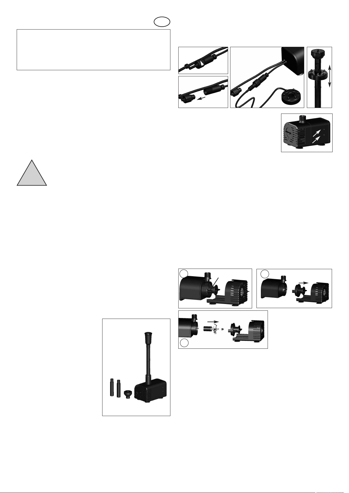
4.1 Operation with LED light ring
B
The accessories include a LED light ring. This light ring can be easily slipped onto
the lifting tube.
lectrical connection is established via the socket on the pump. For this, remove
E
he drain plug, insert the light ring plug in the socket and tighten the cap nut firmly.
t
These instructions relate ONLY to this product and contain important information for using the product for the first time. Please keep these instructions for
ater reference and should always accompany the product in the event of trans-
l
erence to a new user.
f
1. Introduction
ear Costumer,
D
hank you for purchasing the solar light. With this solar light you purchased a product
T
manufactured according to the current state of technology.
This product fulfils all requirements of the valid European and national regula-
ions. The conformity was proved. The relevant declarations and documentati-
t
n are deposited with the manufacturer.
o
To maintain this state and guarantee a safe operation, you as the user will have to follow this operating manual!
2. Safety Instructions
- In case of damages caused by not
ollowing this operating manual, the
f
warranty rights will expire! We exclude
liability for any consequential damages!
!
In these cases any guarantee rights will expire.
-
Due to safety and admission reasons (CE) it is not allowed to arbitrarily reconstruct
and/or change the solar light.
herefore, please keep to the operating manual.
T
he accident prevention rules of the association of the industrial trade cooperative
T
association for electric plants and working material are to be considered in industrial
nvironments.
e
- We exclude liability for property or
ersonal damages caused by inappropriate
p
handling or not following the safety instructions.
3. Intended use
This submersible pump is designed for pumping water in garden ponds, fountains,
water dishes, etc. It can pump water through a hose connection or can be operated
through attached lifting tubes with water sprinklers.
A solar module or a power pack with a voltage of 12 to 24 volts can be used as the
energy source. When used with a solar module, the pump works only if enough
solar radiation strikes the solar module.
A battery box (accessory) is delivered along with this pump. When battery is on, an
LED light (accessory) can be attached to the lifting tube. This gives the fountain a
decorative lighting. The LED light rings are available in different colours.
The delivery rate of the pump can be adjusted using the regulator on the front side
of the pump. The water pump has no On/Off switch. As soon as the pump is connected to its power supply, it starts pumping water.
Light ring
connection
Drain plug
5. Dry run protection
The pump is equipped as standard with a dry run protec-
ion. Two sensor points are provided on the side of the
t
ousing for this. The pump works if these points are
h
under water. If a point projects out of the water, the pump
does not work.
6. Care and maintenance
For optimum performance of the pump, it must be washed occasionally with warm
water depending on the water contamination. To wash the pump, open the housing
as follows:
Note: Please do not use force while dismantling or assembling the pump. The parts
are very fragile and can break easily.
. Disconnect the pumpʼs plug.
1
2. Pull the front cover of the pump forward like a slide gently (Figure 1).
. Turn the front cover of the pump by about 45° clockwise (Figure 1) and carefully
3
pull the cover forward (Figure 2). Watch out for the plastic shaft and the seal while
oing this.
d
4. Carefully drag the impeller out of the pump (if necessary, use pliers). (Figure 3).
5. Now clean all the parts carefully with warm water.
. Then plug the shaft with the impeller carefully into the hole of the pump. Ensure
6
that the shaft is fitted firmly.
7. Now place the cover carefully over the pump. Ensure that the seal is fitted proper-
ly.
8. Turn the front cover again by 45 degrees counter-clockwise into the starting posi-
tion.
9. Slide the lower part of the pump completely into the pump housing.
The pump is ready to use again.
1
turn 45°
2
Sensorpoints
4. Installation and commissioning
1. Roll out the connecting cable of the
pump completely.
2. Ensure that the cap is firmly in place on
the socket.
3. Place the pump in water (please note
Point 5 here).
4. Connect the lifting tubes till they project
out of the water surface. For this, first
attach the reducer to the pump.
5. You can now choose from 2 different
water nozzles.
6. Alternatively, the pump can also be used
for pumping water through a hose. For
this, you just have to attach a hose to the
pumpʼs pipe.
7. Now supply power to the water pump
through a solar module. Use the enclosed plug with cable (red = positive pole,
black = negative pole) for this. If you
have purchased this pump as a complete
solar power system, then the appropriate
plug is already attached to the solar module.
Note: The plug has reverse-polarity protection, no force should be used while inserting. The glass of the solar module is fragile.
Caution! Risk of injury! A broken module cannot be repaired again and must be disposed off in an environmental-friendly way.
8. If the pumping capacity is too high, you can reduce the amount of water. Simply
turn the regulator on the front side of the pump in clockwise direction. Please
do not use force while adjusting. The adjustment range is 45°.
lifting tubes
water nozzle
lifting tubes
water nozzle
3
7. Malfunction
Pump is not pumping water
- Is the pump completely submerged in water? Dry run protection (Point 5)
- Is the polarity of the supply voltage reversed? Cable colour brown = + pole,
blue = negative pole
- Is the pump dirty? Cleaning the pump, see Point 6.
8. Technical data
Operating voltage: 12 - 24 V DC
Degree of protection: IP 68
Power consumption: Approx. 5 W at 12 VDC - approx. 22 W at 24 VDC
Pump lift: Max. 0.9 m at 12 VDC - max. 2,8 m at 24 VDC
Delivery rate: Max. 900 l/h at 12 VDC - max. 1500 l/h at 24 VDC
Operating temp. range: +4 to +40°C
Note: The pump is only suitable for pumping water.
Note: Protect the pump from frost!
During cold winter months, the pump must be taken out of the water and
placed/stored in a warm area. The solar module can spend the winter outdoors.

9. Safety information:
DANGEROUS for children! Children could easily swallow the small parts that come
with this pump and its packaging material. Please keep at a safe distance. These
arts could otherwise lead to choking or suffocation!
p
WARNING against danger of stumbling! Lay out the connection cable such that it
does not create the threat of tripping or stumbling!
AREFUL: material damage! If you set up the solar module without a module hold-
C
er, you must make sure that it is sturdy enough to retain its position. If the module falls
down or a foreign object hits against it, the solar module can be damaged.
10. Spare parts
3 i
nside
2
3 inside
4+5
6
1
11. Accessories
11.1 extender cable (5 m) for water pump
Item-no: 101738
11.2 battery box 12 V/ 7 Ah
Item-no: 101734
7
1. White ceramic shaft: Item No.: 911040
. Pump impeller: Item No.: 911041
2
. Internal rubber bush: Item No.: 911042
3
. Front cover: Item No.: 911043
4
5. Seal for cover: Item No.: 911044
6. Sliding carriages with suction bases: Item No.: 911045
7. Suction bases (4 pieces) Item No.: 911046
. Complete nozzle set: Item No.: 911047
8
7
Manufacturer/Importer
esotec GmbH - Gewerbegebiet Weberschlag 9 - D-92729 Weiherhammer
Tel.-Nr: 09605-92206-0 - Fax.-Nr: 09605-92206-10 - Internet: www.esotec.de
Disposal:
Dear customer,
please cooperate in avoiding waste. When you intend to dispose of the product in
future, please consider that it contains valuable raw materials suited for recycling.
Therefore, do not dispose it of with domestic waste but bring it to a collection point
for the recycling of waste electrical and electronic equipment.
Thank you very much for your cooperation!
Copyright, esotec GmbH
The battery station can be used in the esotec pumping systems Verona,
Toskana, Napoli, Napoli LED, Siena and Siena LED.
The accumulator box is installed between pump and solar module.
-
- The pump may be switched-on and –off via a switch.
The installed accumulator is protected against under- and overcharge.
Two LEDs inform you about the condition of the accumulator.
The system is ready to plug-in and is set up in a matter of minutes.
-
11.3 light rings (only in combination with battery box)
LED light ring white (with 6 weißen LED´s) Item-no: 101790
LED light ring yellow (with 6 yellow LED´s) Item-no: 101791
LED light ring blue (with 6 blue LED´s) Item-no: 101792
LED light ring green (with 6 green LED´s) Item-no: 101793
LED light ring red, green, blue (with each 2 LED´s) Item-no: 101794
5 m Extender cable for light rings Item-no: 101740

Operating manual
G
B
solar battery station 12 V/ 7 Ah
Customer support:
If you have problems or questions regarding this product, simply contact us!
onday to Friday 8 am to 12 noon and 1 pm to 4 pm.
M
y phone: 09605-92206-0
B
y e-mail for ordering spare parts: ersatzteil@esotec.de
B
By e-mail for questions about the product: technik@esotec.de
roduct: Manufacturer Item No.: 101735
P
hese instructions relate ONLY to this product and contain important informa-
T
tion for using the product for the first time. Please keep these instructions for
ater reference and should always accompany the product in the event of trans-
l
erence to a new user.
f
1. Introduction
ear Costumer, thank you for purchasing the solar pump kit.
D
ith this solar pump kit you purchased a product manufactured according to the cur-
W
ent state of technology.
r
This product fulfils all requirements of the valid European and national regula-
ions. The conformity was proved. The relevant declarations and documentati-
t
n are deposited with the manufacturer.
o
o maintain this state and guarantee a safe operation, you as the user will have to fol-
T
low this operating manual!
2. Safety Instructions
- In case of damages caused by not following
this operating manual, the warranty rights
will expire! We exclude liability for any
onsequential damages!
c
!
ue to safety and admission reasons (CE) it is not allowed to arbitrarily reconstruct
D
nd/or change the solar pump kit.
a
Therefore, please keep to the operating manual.
he accident prevention rules of the association of the industrial trade cooperative
T
association for electric plants and working material are to be considered in industrial
environments
- We exclude liability for property or
ersonal damages caused by inappropriate
p
handling or not following the safety instructions.
- In these cases any guarantee rights will expire.
n the evening and in case of decreasing solar radiation, the pump is increasingly sup-
I
plied with energy by the accumulator. The system will run until the accumulator has
reached its deep discharge threshold (approx. 11.8 V). The pump and the LED
ighting are automatically switched-off and the LED is lit up red.
l
The accumulator will then be charged the following morning via the solar module (yellow LED is lit up). Depending on the solar radiation, this process may take a cou-
le of hours.
p
he output voltage of the accumulator station may be adjusted via the controller on
T
the front side. In times with little sunshine, the controller should be adjusted to the
owest setting.
l
4. Assembly/installation and start of operation
. Loosen the screws on the underside of the
1
ousing and remove the cover from the
h
battery box.
. Place the electrical connector on the red
2
brown) cable onto the positive terminal of
(
the rechargeable battery.
. Completely unroll the cable at the pump.
3
4. Insert the plug on the pump cable in the
uilt-in socket “OUTPUT DC 12-24 V” a
b
he accumulator station. Screw the cap nut
t
tight.
Please make sure that the switch is in OFF
position.
5. Completely unroll the cable at the accumulator station.
6. Insert the cable with the socket into the plug of the
olar module. Screw the cap nut tight.
s
. Put the pump into the pond. Please pay attention to the operating manual of the
7
pump. It contains important notes regarding the start of operation and maintenance.
3. Intended Use
- The accumulator station may be used in the esotec pump systems Verona,
Toscana, Napoli, Napoli LED, Siena and Siena LED.
- The accumulator station is installed between pump and solar module.
- The pump may be switched-on or –off via a switch.
- Via a controller, the operating voltage of the pump may be adjusted to 12 and 24 V.
- Operation of the pump optionally via timer or permanent operation
- The integrated accumulator is protected against deep discharge, overcharge
and short circuit.
- Two LEDs provide information about the state of charge and charging of the accumulator.
- The system is plug-in ready and set up within minutes.
Note: The accumulator station must not be positioned and set up in the blazing
sun or in the water.
Mode of operation:
The accumulator station is interconnected between the solar module and the pond
pump.
In case of an optimal solar radiation, the solar module will generate more electrical
energy than required by the pond pump. This excess energy is then stored in the
accumulator and will be available for the pond pump in case of shadow or darkness.
If the battery voltage is within the operative range, the pump will be switched-on and
the green LED is lit up. If the accumulator is discharged, the pump is switched-off and
the red LED is lit up. The yellow LED is lit up as soon as the accumulator is charged.
The electronics protect the accumulator against deep discharge, overcharge or short
circuit.
The charging of the accumulator always has priority over the operation of the
pump.
Throughout the summer months with full solar radiation, this results in the following operating characteristic:
In the morning, the discharged accumulator is charged via the solar module (the yellow LED is lit up). The accumulator is still discharged from the day before (the red
LED is lit up).
The pump is switched-on and the LED is lit up green as soon as the battery voltage
has reached its activation threshold (approx. 12.65 V). In summer with full solar radiation, the solar module will generate enough energy in order to supply the pond pump
with energy and simultaneously charge the accumulator.
8. Leave the switch in the „OFF“ position
and charge the accumulator for 2 to 3
hours during sunshine. When setting the
switch to its “ON” position, the green LED
will be illuminated and the pump starts to
work.
9. The operating voltage of the pump may be
adjusted to 12V and 24 V. This is done by
means of a controller. Thus, the power of
the pump is adjustable.
Note: Full power should only be chosen in
high summer. The increased power consumption leads to a reduction of the maximum operating time of the accumulator.
Note: The plugs and sockets are predcted against inverse polarity. Do not apply force
when inserting the plugs. The glass of the solar module is fragile.
Note: The accumulator station must not be set up in the blazing sun.
5. Operating mode of the accumulator station
5.1 Settings via toggle switch:
1. Position ON : If the built-in accumulator has
the correspondingly high voltage, the pump
starts to run (green LED is illuminated) and the
accumulator is charged if excess energy is
available. In case the capacity of the solar
module should now be reduced due to clouds,
the pump will be supplied with energy via the
accumulator. In the evening, the pump will still
run for some time until the control deactivates
the accumulator (red LED is illuminated).
2. Position 0 (OFF) : The pump is switched-off . The accumulator is charged via the
solar module and the electric energy is stored. The yellow LED is lit up as soon as the
accumulator is charged via the solar module.
Note: In case you would like to achieve a particularly long operating time in the evening, then set the switch to its “OFF” position during the day and to its “ON” position in the evening.

ote: In high summer and in case of a high solar radiation, we recommend leaving
N
the switch in its „ON“ position. Thus, you will achieve the maximum possible runtime
of the pump.
.2 Timer operation:
5
The accumulator station may be operated
ith the timer function via the press
w
witch “Timer On”, “Timer Off”. The functi-
s
n is activated if the switch is pressed.
o
Every hour, the pump will work for approx.
0 minutes.
1
Note: This function shall particularly be
used in case of weak solar radiation or for
longer overshoot time at darkness.
a
6. Short Circuit Protection
he accumulator station is equipped with a short circuit protection in order to prevent
T
ny damage of the electronics by a short circuit at the pump. As soon as the connec-
a
tion of the pump is affected by a short circuit, the state of charge indicator will flash
alternately red and green. In this case, please check the pump for function (e.g.
directly supply the pump via the solar module) and check all plug-in connections for
ightness.
t
7. LED Indicator Lights
-Normal, R-Low:
G
ED is lit up green when the accumulator is sufficiently charged in order to supply the
L
pump with energy. LED is lit up red if the accumulator is discharged. The LEDs are
not lit up when the pump is switched-off.
harge:
C
LED is lit up yellow as soon as the accumulator is charged via the solar module LED
is also lit up in switched-off condition.
8. Exchange of the accumulator
9. Storing throughout the winter
Completely charge the rechargeable battery
in the battery box. Use a sunny day to do this
nd disconnect the battery box.
a
fter charging disconnect the cable from one
A
terminal of the rechargeable battery.
To do this open the housing as described in
ection 8. The battery box should only be sto-
S
red throughout the winter in a fully charged
condition and in a frost free room.
0. Troubleshooting
1
LED does not light green in spite of solar radiation but the yellow LED is lit up.
. The accumulator has not yet been charged sufficiently and the restart threshold is
1
ot reached. The charging process may take several hours in case of insufficient
n
olar radiation.
s
2. Accumulator is exhausted! The accumulator should be exchanged approx. every
years. Please see item 8 of this instruction.
2
he LED is not illuminated green. In spite of solar radiation when switching-off
T
and on again of the switch On/Off , the pump starts to work and the green LED
s illuminated.
i
. The accumulator has not yet reached its restart threshold. The electronics is reset
1
fter the deactivation and activation of the system and the system starts to work
a
without waiting for the restart threshold. This is a normal process and does not
indicate any defect.
ED does not light up green in spite of solar radiation. When the switch
L
On/Off is switched-off and –on, the pump starts working and the green LED is
lit up.
1. The accumulator has not yet reached its re-start threshold. After the system is
witched-off and –on, the electronics is reset and the system starts running wit-
s
hout waiting for the re-start threshold. This is a absolutely normal process and
oes not constitute a defect or failure.
d
LED flashes alternately red and green.
1. There is a short circuit at the output. Please check the pump and all plug-in con-
ections (particularly those of the LED lighting) for tightness.
n
. Please check the cables for damages or bites by animals.
2
We recommend to exchange the accumulator approx. every 2 years. A new identical
in construction accumulator is available from the manufacturer or dealer.
Proceed as follows if you want to exchange the accumulator:
1. Set the switch into the position „OFF“ and unplug the module and the water pump
from the accumulator station.
2. Turn the accumulator station upside down and loosen the screws on the bottom
frame of the accumulator box and carefully remove the cover.
3. Unplug both cables from the accumulator (see picture above). Please memorize
the color of the cables for the positive pole (brown) and negative pole (blue).
4. Remove the accumulator from the housing and insert the new identical in construction accumulator.
5. Reattach the cable lugs on the poles of the accumulator with correct polarity.
Cable color for the positive pole (brown) and negative pole (blue).
6. Close the housing in reverse order.
Note: Please only use an identical in construction accumulator with identical voltage
and capacity.
Note: The old accumulator has to be disposed of in an environmentally sound way.
For this purpose, please contact you local authorities, public collection points or your
dealer.
11. Technical data:
- Accumulator voltage: 12 V
- Accumulator capacity: 7 Ah
- Overload protection: approx. 13,8 V
- Deep discharge protection: approx. 11,8 V
- Voltage threshold for restart: approx. 12,7 V
- Output voltage: 12 - 24 V DC (adjustable)
- Max. load current (output): 800 mA
- Max. connectable module
capacity (input): 20 Wp
- Protection class: IP 44
WARNING of trip hazard! Lay the connection cable so that it does not constitute a
trip hazard.
Battery take-back
- Batteries must not be discarded into domestic waste.
- The consumer is legally required to return batteries after
use, e.g. to public collecting centers or to battery distributors.
- Contaminant-containing batteries are labeled with the sign
“crossed-out trashcan“ and one of the chemical symbols.
Used batteries should be disposed environmentally friendly
and should not be discarded into domestic waste. Your
dealer is legally required to take back old batteries.
Disposal:
Dear customer,
please cooperate in avoiding waste. When you intend to dispose of the product in
future, please consider that it contains valuable raw materials suited for recycling.
Therefore, do not dispose it of with domestic waste but bring it to a collection point for
the recycling of waste electrical and electronic equipment.
Thank you very much for your cooperation!
Manufacturer:
esotec GmbH - Gewerbegebiet Weberschlag 9 - D-92729 Weiherhammer
Tel.-Nr: +49 (0)9605-92206-0 - Fax.-Nr: +49 (0)9605-92206-10
Internet: www.esotec.de - e-mail: info@esotec.de
Copyright, esotec GmbH
Pb
 Loading...