

Page 1

RECORDERS
ESCORT 3016B, 3008B, 3004B
USER SMANUAL
EditionJanuary2007M3008B/03
Page 2

Page 3

WewishtothankyouforacquiringarecorderbyESCORTandfortrustingourcompany. Themain
goalofourdifferentteams(designoffice,production,commercial,after-saleservice )istomatch
withaccuracyyourneedsbydesigningorupdatinghightechnologyproducts.
YouwillfindwithyourrecorderaCD-ROMincluding:
-Theuser smanualofthe ESCORT3016B,ESCORT3008Band ESCORT3004B
appliance
-the"ESCORTView"softwarethatallowsyoutosaveandworkwithyourrecordingfiles
underWindows .
Wewouldlikeyoutoreadcarefullythisuser smanualforanoptimumuseofyourrecorder.
Copyright ESCORT,2006.Allrightsreserved
Anycopyofthisdocument,totallyorpartially,is submittedtoanautorisationby ESCORT.
Page 4

Page 5

GARANTY
Yourinstrumentisguaranteedforoneyearinpartsandworktimeagainstanydefaultofmanufacture
and/orcontingenciesinthefunctioning. Thisguarantystartsatthedateofdeliveryandends365
calendardayslater.
Iftheapplianceissubjecttoaguarantycontract,thiscontractcancelsandreplacestheabove
mentionedconditionsofguaranty.
Thisguarantydoesnotincludeanyfaultofuseand/orerrorofhandling.
Incaseofuseoftheguaranty,theusermustsendbacktheconcernedappliancetoourfactory:
ESCORT InstrumentsCorporation
3F,No6,Alley6,Lane45,Pao-HsinRoad,Hsin Tien,231 Taipei, TaiwanR.O.C.
TEL:886-2-2913-1325
FAX:886-2-2918-3929
http://www.escorttw.com
Theaccessoryitemsfurnishedasstandardwiththeappliance(cables,plugs )andtheoptional
accessoryitems(bag,case )areguaranteedfor3monthsagainstanydefaultofmanufacture.
Thefactoryoptionsintheapplianceareguaranteedforthesametimeastheappliance.
Whattodoincaseofmalfunction?
Incaseofmalfunctionorforanyproblemofuse,pleasecontactthetechnicalassistanceby ESCORT
InstrumentsCorporation.
Atechnicianwilltakeyourmailinchargeandwillgiveyouanynecessaryinformationtosolveyour
problem.
Whattodoincaseofcrash?
Incaseofcrashoftheappliance,pleasejoinourafter-salesservice.
Page 6

Page 7

CONTENTS
1.IMPORTANT INFORMATION..............................................................................................................................1.1
1.1.CAUTIONS ................................................................................................................................................................1.1
1.2.SECURITY INSTRUCTIONS .........................................................................................................................................1.1
1.3.SYMBOLS AND DEFINITIONS .....................................................................................................................................1.2
1.4.CONFORMITY AND RESTRICTIONS OF THE APPLIANCE ..............................................................................................1.2
2.PRESENTATION......................................................................................................................................................2.1
2.1.GENERAL..............................................................................................................................................................2.1
2.2.DESCRIPTION.......................................................................................................................................................2.2
2.2.1.Rear side (or top side)...................................................................................................................................2.2
2.2.2.Front side.......................................................................................................................................................2.3
2.3.THE LCD SCREEN................................................................................................................................................2.3
Description of the screen.............................................................................................................................................2.3
2.4.KEYS......................................................................................................................................................................2.4
2.5.THUMB WHEEL...................................................................................................................................................2.5
2.6.LOCKING THE KEYBOARD...............................................................................................................................2.5
2.7.USE OF A MOUSE................................................................................................................................................2.5
2.8.USE OF AN EXTERNAL KEYBOARD...............................................................................................................2.5
2.9.UPDATING THE INTERNAL SOFTWARE........................................................................................................2.6
2.10.USE OF THE SUPPORT LEG OF 8440............................................................................................................2.6
3.INITIALISATION AND PRECAUTIONS OF USE..............................................................................................3.1
3.1. ESCORT 3008B LOADING THE RECORDING PAPER....................................................................................3.1
3.1.1.Storage precautions of the records................................................................................................................3.2
3.2.POWER SUPPLY...................................................................................................................................................3.2
3.2.1.Fuse...............................................................................................................................................................3.2
3.2.2.Power up of ESCORT 3008B.........................................................................................................................3.3
3.2.3.Power up of ESCORT 3016B and ESCORT 3004B.......................................................................................3.4
3.3.CONFIGURATION ON POWER-UP....................................................................................................................3.4
3.4.CONNECTION TO THE MEASURE NETWORK...............................................................................................3.5
3.4.1.Measure of voltage.........................................................................................................................................3.5
3.4.2.Measure of temperature with a thermocouple...............................................................................................3.5
3.4.3.Measure of temperature with a PT100..........................................................................................................3.5
3.4.4.Measure of intensity.......................................................................................................................................3.6
3.4.5.Connection of the grounding.........................................................................................................................3.6
3.5.ROUTINE MAINTENANCE ..........................................................................................................................................3.7
3.6.CALIBRATION OF THE OFFSETS .................................................................................................................................3.7
3.7.FACTORY ADJUSTEMENT ..........................................................................................................................................3.8
4.USE..............................................................................................................................................................................4.1
4.1. « MODE » KEY .........................................................................................................................................................4.1
4.2. « HELP » KEY...........................................................................................................................................................4.2
4.3. « SET UP » KEY.........................................................................................................................................................4.3
4.4. « CHART » KEY........................................................................................................................................................4.5
4.5. « CHANNELSSET UP» KEY .......................................................................................................................................4.6
4.5.1.Analogical channels.......................................................................................................................................4.6
4.5.2.Logic channels...............................................................................................................................................4.8
4.6. « CHANNELON/OFF» KEY ........................................................................................................................................4.9
4.7. « DISPLAY » KEY ...................................................................................................................................................4.10
4.7.1.Display F(t) (oscilloscope mode).................................................................................................................4.10
4.7.2.Display XY...................................................................................................................................................4.12
4.7.3.Digital display.............................................................................................................................................4.12
4.8.DIRECTION KEYS ....................................................................................................................................................4.12
4.9. « TRIGGER » KEY ...................................................................................................................................................4.13
Page 8

4.10. « REPLAY » KEY ...............................................................................................................................................4.14
4.11. « START/STOP » KEY ........................................................................................................................................4.15
4.12.PAPER-FEED KEY...............................................................................................................................................4.16
5.DIAGRAMS...............................................................................................................................................................5.1
5.1.POSITIONS OF THE CHANNELS ..................................................................................................................................5.2
5.2.CHANGE DIAGRAMS.................................................................................................................................................5.3
6.TRIGGERS................................................................................................................................................................6.1
6.1.TRIGGERING WITH ANALOGICAL CHANNELS ............................................................................................................6.2
6.1.1.Single threshold.............................................................................................................................................6.2
6.1.2.Several thresholds.........................................................................................................................................6.3
6.1.3.Trigger according to thresholds....................................................................................................................6.4
6.1.4.Trigger according to the slope......................................................................................................................6.5
6.2.TRIGGERING WITH LOGICAL CHANNELS ...................................................................................................................6.6
7.MATHEMATICAL CALCULATIONS..................................................................................................................7.1
7.1.DEFINITIONS ............................................................................................................................................................7.1
7.2.TYPES OF CALCULATIONS ........................................................................................................................................7.2
8.DIRECT MODE........................................................................................................................................................8.1
8.1.CONFIGURATION OF THE PLOTTING..........................................................................................................................8.1
8.2.TRIGGERING PLOTTING ............................................................................................................................................8.3
8.3.REARMAMENT OF THE PLOTTING .............................................................................................................................8.5
8.4.WRITING DATA ........................................................................................................................................................8.5
8.5.EXAMPLE OF PLOTTING PROGRAM ...........................................................................................................................8.5
9.MEMORY MODE.....................................................................................................................................................9.1
9.1.CONFIGURATION AND TRIGGERING OF THE ACQUISITION.........................................................................................9.1
9.2.SAMPLING PERIOD ...................................................................................................................................................9.2
9.3.INTERNAL MEMORY, BLOCKS...................................................................................................................................9.3
9.4.TRIGGERING POSITION .............................................................................................................................................9.3
9.5.DOUBLE TRIGGER MODE ..........................................................................................................................................9.4
9.6.RECORDING .............................................................................................................................................................9.4
9.7.MEMORY OUTPUT ....................................................................................................................................................9.7
10.GO/NOGO MODE..................................................................................................................................................10.1
10.1.CONFIGURATION AND TRIGGERING OF THE ACQUISITION ..................................................................................10.1
10.2.CREATION OF THE FRAME .................................................................................................................................10.2
10.3.USE OF THE FRAME ...........................................................................................................................................10.4
11.FILE MODE............................................................................................................................................................11.1
11.1.CONFIGURATION AND START OF THE ACQUISITION ...........................................................................................11.1
11.2.LIMITS...............................................................................................................................................................11.2
11.2.1.Binary file....................................................................................................................................................11.2
11.2.2.Asciifile.......................................................................................................................................................11.2
12.FILE MANAGEMENT...........................................................................................................................................12.1
12.1.GENERAL ..........................................................................................................................................................12.1
12.2.MANAGEMENT OF THE CONFIGURATION FILES ..................................................................................................12.2
12.2.1.Saving the configuration files......................................................................................................................12.3
12.2.2.Loading the configuration files....................................................................................................................12.4
12.3.MANAGEMENT OF THE ACQUISITION FILES........................................................................................................12.4
12.3.1.Saving the acquisitions................................................................................................................................12.4
12.3.2.Loading the acquisition files........................................................................................................................12.6
12.4.PC SOFTWARE FOR ANALYSIS.................................................................................................................12.6
12.4.1.File transfer with FTP.................................................................................................................................12.7
12.4.2.Display withESCORT_VIEW.....................................................................................................................12.8
13.PRINTING WITH ESCORT 3016B AND ESCORT 3004B................................................................................13.1
13.1.PLOT SET UP AND LAUNCH ................................................................................................................................13.1
Page 9

13.2.PRINTER SETUP .................................................................................................................................................13.3
14.INPUTS / OUTPUTS...............................................................................................................................................14.1
14.1.SUPPLEMENTARY INPUT / OUTPUT CONNECTOR.................................................................................................14.1
14.2.LOGICAL INPUTS................................................................................................................................................14.2
14.2.1.Use...............................................................................................................................................................14.2
14.3.ALARM OUTPUTS ...............................................................................................................................................14.3
14.3.1.Use...............................................................................................................................................................14.3
14.4.POWER SUPPLY OUTPUT ....................................................................................................................................14.3
14.5.KEYBOARD INPUT..............................................................................................................................................14.3
14.6.MOUSE INPUT ....................................................................................................................................................14.4
14.7.XGA SCREEN OUTPUT.......................................................................................................................................14.4
14.8.RS232...............................................................................................................................................................14.4
14.9.USB INTERFACE................................................................................................................................................14.5
14.10.ETHERNET RJ45 INTERFACE ..........................................................................................................................14.5
15.ETHERNET INTERFACE.....................................................................................................................................15.1
15.1.INTERFACE ETHERNET.......................................................................................................................................15.1
15.2.PROGRAMMING LANGUAGE...............................................................................................................................15.2
15.2.1.Format of the reception messages...............................................................................................................15.2
15.2.2.Format of the emission messages................................................................................................................15.4
15.3.STANDARD INSTRUCTIONS.................................................................................................................................15.5
15.4.INDICATION OF THE STATUS OF THE APPLIANCE ................................................................................................15.6
15.4.1.Structure of the status data..........................................................................................................................15.6
Registers of service request........................................................................................................................................15.7
15.4.3.Registers of standard events........................................................................................................................15.8
15.4.4.Register of the alarms..................................................................................................................................15.9
15.4.5.Using the structure of status data..............................................................................................................15.10
15.5.PROGRAMMING DICTIONARY ...........................................................................................................................15.11
15.5.1.Setup..........................................................................................................................................................15.11
15.5.2.Parameters of the channels........................................................................................................................15.12
15.5.3.Functions of the channels and between the channels................................................................................15.13
15.5.4.Changing mode..........................................................................................................................................15.13
15.5.5.Current function(page).............................................................................................................................15.13
15.5.6.Chart..........................................................................................................................................................15.14
15.5.7.Triggerings................................................................................................................................................15.15
15.5.8.Triggers.....................................................................................................................................................15.16
15.5.9.Memory mode............................................................................................................................................15.17
15.5.10.Reloadings, real-time savings...............................................................................................................15.17
15.5.11.Launching plotting and recording........................................................................................................15.18
15.5.12.Diagrams...............................................................................................................................................15.18
15.5.13.Direct display........................................................................................................................................15.19
15.5.14.Replay (memory output)........................................................................................................................15.19
15.5.15.Service request......................................................................................................................................15.20
15.6.ERROR MESSAGES............................................................................................................................................15.20
16.TECHNICAL SPECIFICATIONS.........................................................................................................................16.1
16.1.ISOLATED INPUTS ..............................................................................................................................................16.1
16.1.1.General characteristics................................................................................................................................16.1
16.1.2.Voltage recording........................................................................................................................................16.1
16.1.3.RMS recording.............................................................................................................................................16.1
16.1.4.Temperature recording................................................................................................................................16.2
16.1.5.Sampling......................................................................................................................................................16.2
16.1.6.Bandwidth....................................................................................................................................................16.2
16.2.MULTIPLEXED INPUTS .......................................................................................................................................16.3
16.2.1.General characteristics................................................................................................................................16.3
16.2.2.Voltage recording........................................................................................................................................16.3
16.2.3.RMS recording.............................................................................................................................................16.3
16.2.4.Temperature recording................................................................................................................................16.4
16.2.5.Sampling......................................................................................................................................................16.4
16.2.6.Bandwidth....................................................................................................................................................16.4
Page 10

16.3.SUPPLEMENTARY INPUTS / OUTPUTS.................................................................................................................16.4
16.3.1.Logical channels..........................................................................................................................................16.4
16.3.2.Alarm outputs..............................................................................................................................................16.5
16.3.3.External power supply.................................................................................................................................16.5
16.4.PAPER ...............................................................................................................................................................16.5
16.5.DISPLAY............................................................................................................................................................16.5
16.6.MEMORY ACQUISITION .....................................................................................................................................16.5
16.7.FILE ACQUISITION .............................................................................................................................................16.6
16.8.COMMUNICATION INTERFACE ...........................................................................................................................16.6
16.9.MISCELLANEOUS ..............................................................................................................................................16.6
16.9.1.USB Connectors..........................................................................................................................................16.6
16.9.2.Screen connector.........................................................................................................................................16.6
16.10.ENVIRONMENTAL CONDITIONS ESCORT 3008B....................................................................................................16.6
16.10.1.Weather conditions.................................................................................................................................16.6
16.10.2.Mains power supply................................................................................................................................16.6
16.10.3.Dimensions, weight.................................................................................................................................16.7
16.11.ENVIRONMENTAL CONDITIONS ESCORT 3016B AND ESCORT 304B..................................................................16.7
16.11.1.Weather conditions.................................................................................................................................16.7
16.11.2.Mains power supply................................................................................................................................16.7
16.11.3.Dimensions, weight.................................................................................................................................16.7
Security – isolation class – installation category......................................................................................................16.8
16.11.5.Electromagnetic compatibility................................................................................................................16.8
16.12.MISCELLANEOUS ..............................................................................................................................................16.9
16.12.1.Internal saving battery............................................................................................................................16.9
16.13.ACCESSORY ITEMS ..........................................................................................................................................16.10
16.13.1.Items furnished with the appliance.......................................................................................................16.10
16.13.2.Optional accessory items......................................................................................................................16.10
16.13.3.Expandableitems..................................................................................................................................16.10
17.APPENDIX...............................................................................................................................................................17.1
17.1.INFORMATION ABOUT THE RANGES OF THE INPUTS ...........................................................................................17.1
17.1.1.Voltage-type inputs......................................................................................................................................17.1
17.1.2.Thermocouple J type input..........................................................................................................................17.2
17.1.3.Thermocouple K type input.........................................................................................................................17.2
17.1.4.Thermocouple T type input..........................................................................................................................17.3
17.1.5.Thermocouple S type input..........................................................................................................................17.3
17.1.6.Thermocouple B type input..........................................................................................................................17.4
17.1.7.Thermocouple E type input..........................................................................................................................17.4
17.1.8.Thermocouple N type input.........................................................................................................................17.5
17.1.9.Thermocouple W5 type input.......................................................................................................................17.5
17.2.ACCURACY OF THE THERMOCOUPLE MEASUREMENTS ......................................................................................17.6
17.3.ACCURACY OF THE PT100 MEASUREMENTS .....................................................................................................17.7
17.4.ACCURACY CLASS – INDEX OF CLASS................................................................................................................17.8
Page 11

Page 12

1-Important informations
1.IMPORTANT INFORMATION
Pleasereadthefollowinginstructionscarefullybeforeusingyourrecorder
1.1.Cautions
Donotuse theproductforanyotherpurposethanthoseintended.
Usenormalisedcables forconnectingtheappliancetothepointsofmeasure.
Usethepowercableprovided toavoidanydamagetotheapplianceandtoensureits
measuringcharacteristics.
Topreventanyelectricshockhazard, neverplugorunplugthemeasuringcableswhen
theyareconnectedtoanelectricpowersupply.
Donotuseinwetenvironment.
Donotuseinexplosiveenvironment.
Incaseoffailureorforthemaintenanceoftheappliance,onlyqualifiedpersonnel
shouldbeallowedtointervene.Insuchacase,itisnecessarytousesparepartsby ESCORT.
Donotopentheappliancewhenalive.
1.2.Securityinstructions
Foracorrectuseoftheappliance,itisnecessarythatusersabidebythesecuritymeasuresas
describedinthismanual.
Somespecificwarningsappearallalongthismanual.
Incaseofneeds,warning symbolsare shownontheappliance:
ThisisaCLASS1appliance:anyinnerorouterelectricdefaultoftheapplianceinrelation
withitsuseisevacuatedtothegroundthatensuresthesecurityoftheuser.
YOUMUSTNOT unplugtheprotectivegroundingoftheappliance
1.3.Symbolsanddefinitions
Page1.1
Page 13
1-Important informations
Symbolsthatappearinthismanual:
Warning: potentialdangerfortheuser
Attention: potentialdangerfortheapplianceand/ortheconnectedequipment
Remark: Importantinformation
Symbolsthatappearontheappliance:
Danger(HighVoltage): immediatecorporalhazard
Attention: refertothemanual.Possibilityofdamagestotheconnected
equipmentortotheapplianceitself.
Grounding: reachablepartsboundtothegroundingoftheappliance
1.4.Conformityandrestrictionsoftheappliance
The ESCORT3016B,3008B,3004BrecordersareinconformitywithCEI61010-1(2001-
02).
Seechapter "Technicalspecifications ".
Attention:Neversetavoltagehigherthanthemaximumadmissiblevoltage
betweentheterminalsandrelativelytotheground.
Page1.2
Page 14

2-Presentation
2.PRESENTATION
2.1.GENERAL
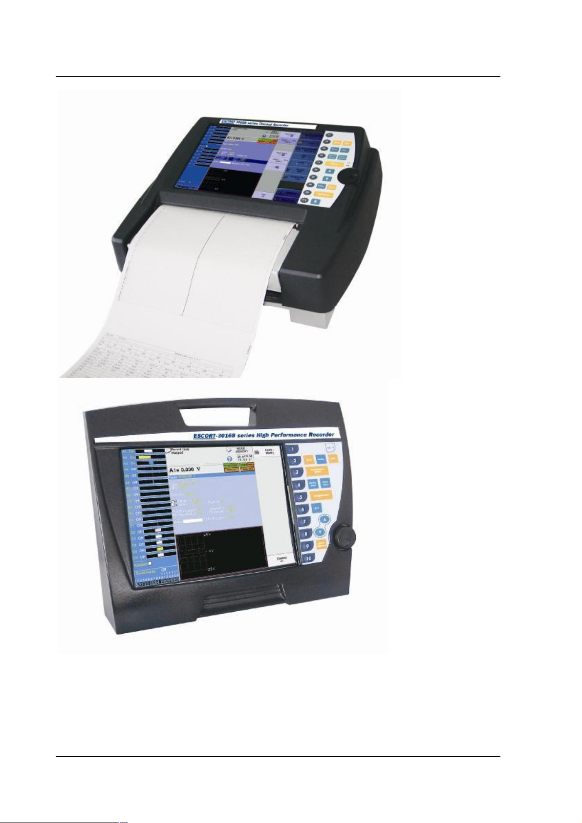
The ESCORT3008B,ESCORT3016Band ESCORT3004Bareprogrammablerecordersdesigned
tomeasureandrecordon6to36analogicalchannels,voltages,currents,temperatures,etc.and16
logicalchannels(eventmarkers).
The ESCORT3008Bappliancehasabuilt-inthermalprinterforreal-time signalsrecording.Itis
suitablewith6to36analogicalchannelsisolatedormultiplexednon-isolated .
The ESCORT3016Bisidenticaltothe ESCORT3008Bbutwithoutreal-timerecordingonpaper.
Itissuitablewiththesamekindandnumberofchannels.
The ESCORT3004Bmorecompact,isthesamethanthe ESCORT3016Bwithonly6isolated
channelsinstandard.
2typesofinputsareproposed:
-isolatedinputsthough6-channelsmodules,upto3modules
-non-isolateddifferentialinputs,multiplexedby12-channelmodules,upto3modules.
Ithasvariousfunctioningmodes:
-aDirectmode,foracquisitionprintedonpaper,availableonlyon ESCORT3008B
-aMemorymode,foracquisitiononquickinnermemory
-aFilemode,foracquisitiononinnerharddriveorUSBkey
-aGoNogomode,foracquisitiononapre-recordedframe.
The"operator-recorder"dialogismadeeasierthankstoeasy-to-readmenusonawide LCDscreen.
Themeasuringparametersareeasytoprogram.Youcanprogramtheparametersthroughthe
keyboardandthethumbwheelonthefrontside,orthroughamouseandaexternalkeyboard.
The ESCORT3008B,ESCORT3016Band ESCORT3004Brecorderscanbeentirelyprogrammed
throughanEthernetlink.
Page2.1
Page 15
2-Presentation
Page2.2
Page 16
2-Presentation
2.2.DESCRIPTION
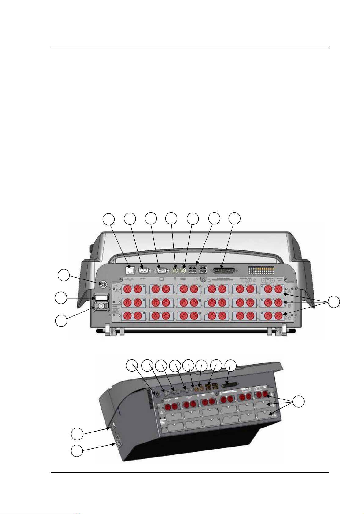
Allkindofrecorderhavethesameinputs/outputsconnectorsattherearsideforthe ESCORT
3008B,oratthetopsideforthe ESCORT3016Band ESCORT3004B.
2.2.1.Rearside(ortopside)
1-aRJ45connectorforthe ETHERNET10/100BaseTinterface
2-aSUB-D9-pinconnector(RS232notused)
3-aSUB-D15-pinconnectorforanexternalscreentypeXGA(1024x768)
4-aMINI-DINconnectorforthemousetypePCPS2
5-aMINI-DINconnectorforthekeyboardtypePCPS2
6-4USBconnectorsforkeyboardandmousetypePC,orformemorykeys
7-aSUB-D25-pinconnectorforthe16logicalinputsandafewalarmoutputs
8-accesstothe3modulesA,B,Coftheinputs(isolatedornotaccordingtothe
configurationoftheappliance)
9-groundingterminal
10-ON/OFFswitch
11-mainssocket
ESCORT3008B
9
10
11
1
2
3 4
ESCORT3016BandESCORT3004B
1
9
2 3
5
6 7
6
7
8
5
4
8
10
11
Page2.3
Page 17
2-Presentation
Isolatedinputmodulesincludeforeachinput2safetyterminals:
-1redterminal:input"+"
-1blackterminal:input"-"
Non-isolateddifferentialinputmodulesincludeforeachinput5screwterminals:
-2terminalsmarked+and forthevoltageinput
-2terminalsmarkedI+andI-forthePT100input
-1groundingterminal
Forallotherinput/output,seechapter "Inputs/Outputs".
2.2.2.Frontside
Thefrontsideoftherecordersincludes:
-acolourLCDback-lit TFTscreen
-akeyboardwithfunctionkeysandmenukeys
-athumbwheel
-asetincludingaprintingtableandpaper-feedforthe ESCORT3008B
2.3.THELCDSCREEN
2.3.1.Descriptionofthescreen
10
9
8
1
2 3 4
5
7
Page2.4
6
Page 18
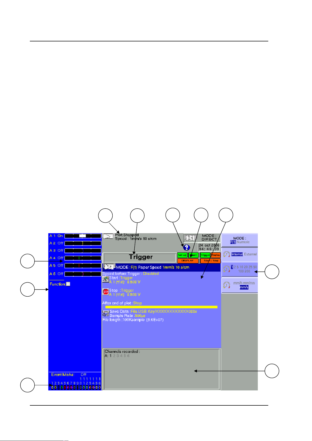
Variouszonesonthescreen:
1-TITLEofthecurrentmenu(exceptforafewvisualisationmenus)
2-HELP:accesstoin-lineassistanceanduser smanual
3-FUNCTIONS:accesstothemainfunctionswiththemouse;hasthesamefunctionsas
thefront sidekeyboard
4-PARAMETERS:namesoftheset-upparametersandtheircurrentvalues
5-VALUES:possiblevaluesoftheparameterscurrentlymodified;selectionthroughakey
fromF1toF10thenmodificationwiththethumbwheelordirectlywiththemouseorthe
externalkeyboard
6-INFORMATIONrelativetotheacquisition(validatedinputs,totalacquisitiontime,
positionsofthetriggers )
7-LOGICALINPUTS:real-timestatusofthelogicalchannels
8-FUNCTION:calculationfunctionsbetweenthechannels
9-ANALOGICALINPUTS:bargraphofthecurrentvaluesoftheinputs
10-GENERALSTATE:modeofacquisition,dateandhour,statusoftheacquisitionorthe
printing.
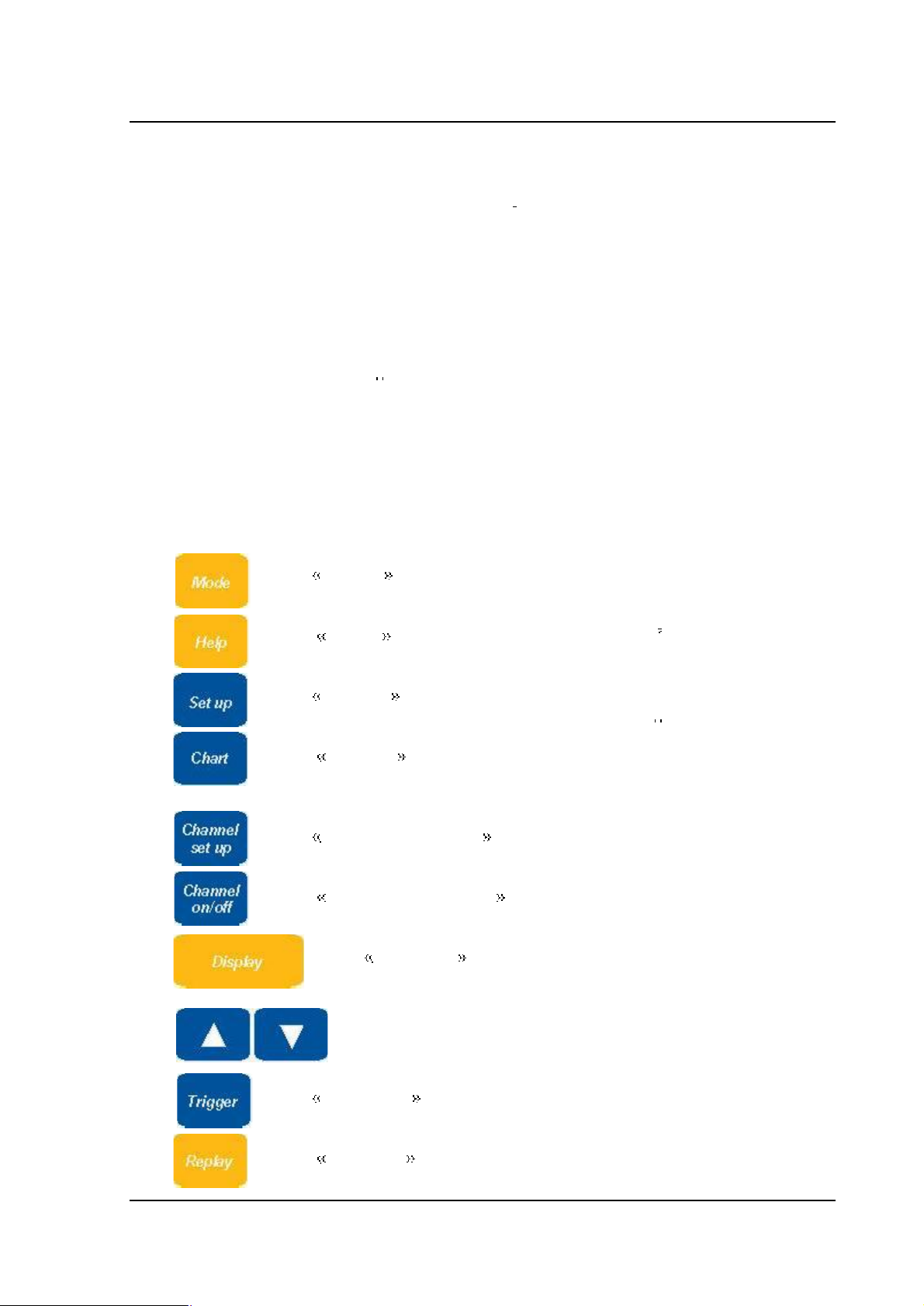
2.4.KEYS
2-Presentation
MODE :choiceofthefunctioningmodeoftherecorder: DIRECT
(ESCORT3008Bonly), MEMORY, GONOGO or FILE
HELP :displaysa"help"windowortheuser smanual
SETUP :generalconfigurationoftheappliance(language,dateand
hour,alarmoutputs,updateoftheinnersoftware )
CHART :parametersoftheprintingonthermalpaper(ESCORT
3008Bonly)
CHANNELSETUP :accesstotheparametersofeachchannel,
accesstothefunctionsbetweenchannels
CHANNELON/OFF :choiceofthechannelstobeineach
acquisition(onpaper,onscreen,ininnermemoryandonfile)
DISPLAY :printingonscreenofthevalidatedchannels(in
graphicalformsf(t),XYordigitalform),oscilloscopemode,
measurecursors,zoom,calculations
directionkeys:choiceoftheparametertomodify
TRIGGER :triggeringparameteroftheacquisitions(onpaper,in
innermemoryoronfileaccordingtothecurrentMODE)
REPLAY :printingonscreenoftheacquisitionsininnermemoryor
onfile,measurecursors,zoom,calculations
Page2.5
Page 19

2-Presentation
thermalpaper-feedkeyfor ESCORT3008B:quickadvanceofthepaperthrough
START/STOP :launchoftheprintingonthermalpaperinDIRECT
MODEon ESCORT3008B,launchoftheacquisitioninanyotherMODE
continuouspress
F10
F1toF10keys:choiceoftheparametertomodifybeforeactiononthethumb
wheel
2.5.THUMBWHEEL
Itmakesitpossibletomodifythevalueoftheselectedparameterthroughincrement/decrement.In
tracevisualisationf(t),italsomakesitpossibletomovethemeasurecursorsonthescreen.
2.6.LOCKINGTHEKEYBOARD
Simultaneouslytriggeringtheandkeyslocksthekeyboard. Themessage
Keyboardlocked appearsontherighttopofthescreen.
2.7.USE OFAMOUSE
Youcanusetherecorderwithamouseconnectedonthemouse-portPS2oronanUSBconnector.
Youcanthenuseitineverypartsofthescreen:
-directlydisplaytheconfigurationofachannelbyclickingonitsbargraph(zone9)
-validate/invalidateachannelbyclickingonitsON/OFFindication(zone9)
-displaytheconfigurationofthelogicalchannels(zone7)
-validate/invalidatethelogicalchannelswithitsON/OFFindication(zone7)
-chooseoneofthefunctionsoftherecorder(zone3)
-accessthehelpwindow(zone2)
-selectaparametertomodify(zone4)
-modifytheparameterselectedbyclickingthepropositions(zone5):rightmouse-keyto
increment,leftmouse-keytodecrementorcentralwheelinbothsenses
-movethemeasurecursorsindirectvisualisationandmemoryoutput
2.8.USE OFANEXTERNALKEYBOARD
YoucanalsouseanexternalkeyboardconnectedonthekeyboardportPS2oranUSBconnector.
The ESC keydisplaysthemainfunctionsoftherecorder.
YoucanthenaccessthefunctionswiththekeysF1toF10ofthekeyboard.
Thekeys PgUP and PgDown canbeusedinsteadofthethumbwheeltoincrement/
decrementtheparameters.
Page2.6
Page 20

2-Presentation
2.9.UPDATINGTHE INTERNALSOFTWARE
Theinternalsoftwareisregularlyupdatedwithitslatestevolutions. Thisupdatesareavailableon
ourInternetsite.
Fortheupdating,copythe TARfilefurnishedtoanUSBkey.PlaceitononeoftheUSB
connectorsattherear sideoftheappliance.
Pushthekey,thenselecttheparameterline Softwareupdate andvalidatewith
F1 Modify .
Theinternalsoftwarewillautomaticallycopytherequiredfilesinthenewversion.
Turnoffandonaftertheupdatingiscomplete.
2.10.USE OFTHESUPPORTLEG OFESCORT3008B
Thesupportlegunderthe ESCORT3008Bappliancemakesitpossibletouseitverticallywitha
little slanttotherearwithbettervisualease.
Attention:Itisnecessarytolockthesupportleg.
Todoso,wheninplace,pressstronglyuponthesidesinordertolockitonitssupport.
Toclose,pullonboth sidesatthesametime.
Page2.7
Page 21
3 Initialisation
3.INITIALISATIONandPRECAUTIONSOFUSE
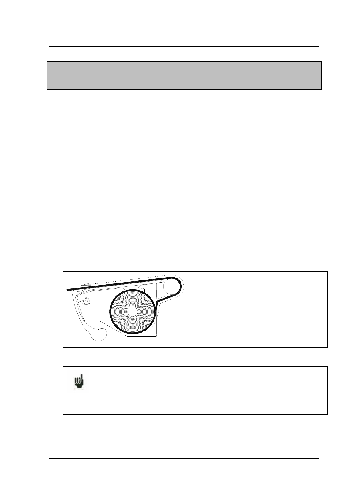
3.1.ESCORT3008BLOADINGTHERECORDINGPAPER
ThepaperusedforESCORT3008Bisprovidedwithanendcutsothatitsloadingismadeeasier.
Incaseofanusedroll,you dbettercutitagainthisway.
NOTE:Onlyone sideofthepaperis sensibletoheat.Reverseitwhileloadingwouldleadtono
printing.
Operationstoproceed:
-openthedoortowardyou
-puttheaxisofthepaperinsidetheroll
-settheaxisofthepapertogetherwiththerollinplaceatthebottomofthereceptor.Theaxis
mustbepositionedinsidethenotchesonboth sidesofthereceptor.
Thewords "ref.no."mustappearontheleft
-introducethepointofthepaperintothe slotonthestainlesssteelreceptor
-collectthepaperwiththepointabovetherollunderthecutter
-pullthepaper sheetafewcentimetresuntilitiswellpositioned
-closethetable.
Installationoftherollpaper
Abadloadingofthepapercoulddamagethemotorandthethermalhead.
Specialattention shouldbepaidtoit.
Therecordershouldalwaysbeprovidedwithpaper,forlong-timedirectcontactwiththeroll
willdamagethethermalhead.
Page3.1
Page 22
3 Initialisation
3.1.1.Storageprecautionsoftherecords
Inordertopreservethequalityofthepaperrecords,itisadvisabletoabidebysomehandling
precautions:
-neveruseplastic-coatedpockets
-storeawayfromlight,inadryandcoolplace
Paperboard-coatedpocketsarenotadvisable.
3.2.POWERSUPPLY
Therecordersworkwithnormalisedmains(seechapter"technicalspecifications").
Ithasbeendesignedforindooruse.
MAINSCONNECTION
Thisappliancesmustbeconnectedtothemainswiththecablefurnished.
SECURITY
Thisappliancesare securityclass I appliancesaccordingtotheCEI1010(NF EN61010)
classification Securityregulationsforelectricappliancesformeasure,regulationandlaboratory
Italsoshouldbesuppliedwithaone-phasenetworkaccordingtothe installationcategoryII
(overvoltagecategory).
GROUNDING
Thisinstruments shouldbegroundedwiththecablefurnished.
Interruptingthegroundingcableinsideoroutsidetheinstrumentis
FORBIDDEN andmakestheappliance DANGEREOUS
3.2.1.Fuse
Theprotectingfuseofthemainscannotbereachedbytheuser.Incaseofdefaultofpowersupply,
contacttheafter-salesservice.
TypeforESCORT3008Bsupply:5A,20mmquick-fuseHBC
TypeforESCORT3016Band ESCORT3004Bsuuply:2,5A,20mmquick-fuseHBC
Page3.2
Page 23
3 Initialisation
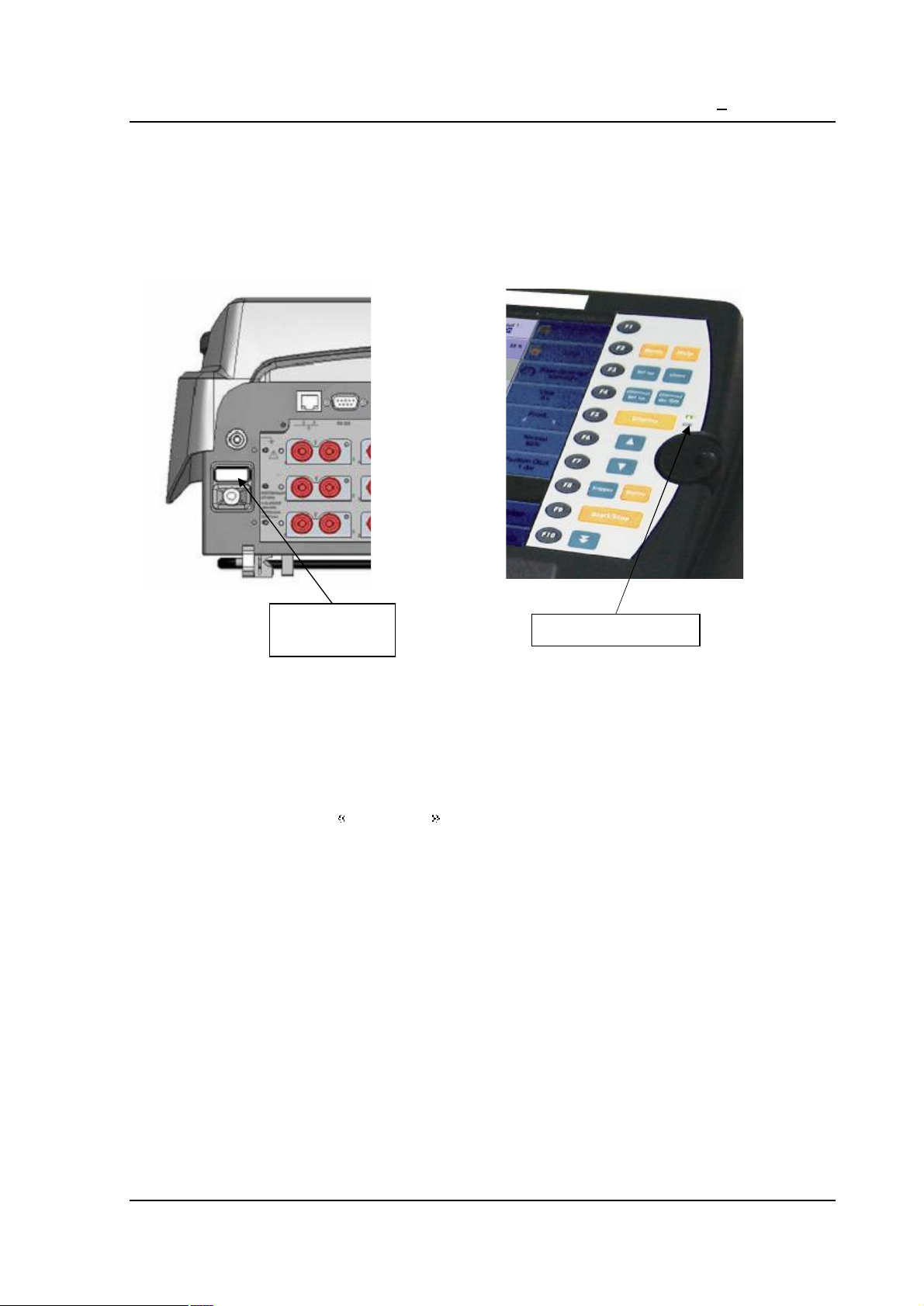
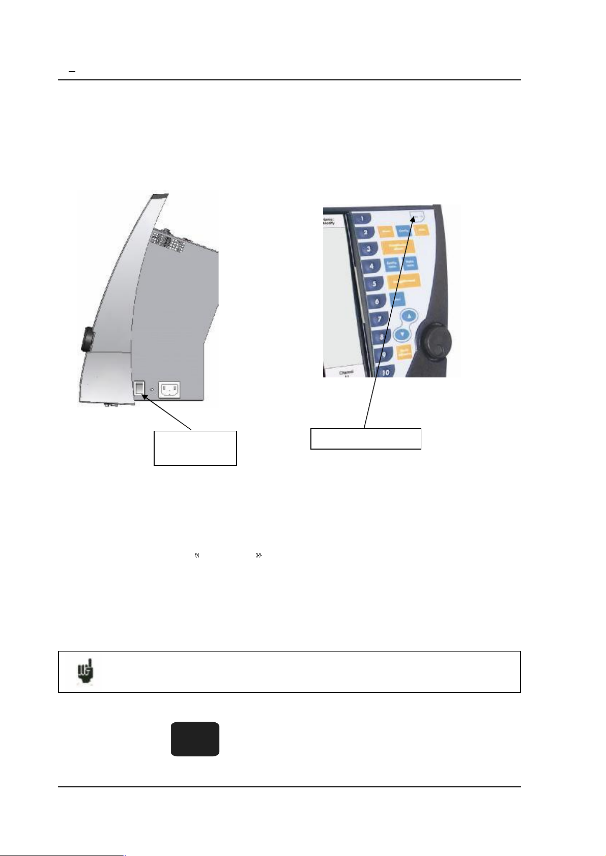
3.2.2.PowerupofESCORT3008B
Power-upoftherecorderESCORT3008Bisproceededfromtherear sideoftheappliancewiththe
On/Off switchtothe sidemarked "I".
ALEDmarked"ON"onthefrontsideonthekeyboardwillconfirmthepower-upoftheappliance.
ON/OFF
switch
Afterinitialisationoftheinternalsoftware,therecorderwilldisplayanintroducingwindowwith:
-theversionofthesoftware:Versionx.y
-thenumberofchannels:6 ,12,18ormore
thenentersautomaticallythe DISPLAY mode(oscilloscope).
Power-upLED
Page3.3
Page 24
3 Initialisation
3.2.3.PowerupofESCORT3016BandESCORT3004B
Power-upoftherecordersESCORT3016BandESCORT3004Bisproceededfromtheright sideof
theapplianceswiththe On/Off switchtothe sidemarked "I".
ALEDmarked"ON"onthefrontsideonthekeyboardwillconfirmthepower-upoftheappliance.
ON/OFF
switch
Afterinitialisationoftheinternalsoftware,therecorderwilldisplayanintroducingwindowwith:
-theversionofthesoftware:Versionx.y
-thenumberofchannels:6 ,12,18ormore
thenentersautomaticallythe DISPLAY mode(oscilloscope).
Power-upLED
3.3.CONFIGURATION ONPOWER-UP
Onpower-up,theappliancesrununderthelatestconfigurationatswitching-off(eithernormalor
afterpowershut-down).
Ifnoconfigurationisrunatpower-up,contacttheafter-sales service
Incaseofwronginitialconfiguration,youcanstarttheappliancewiththedefaultconfiguration:
youmustpressthekeyuntildisplayoftheinitialisingpage.
Page3.4
F1
Page 25
3 Initialisation
3.4.CONNECTIONTOTHEMEASURENETWORK
3.4.1.Measureofvoltage
Isolatedinputmodule: themeasureofvoltageismadebetweentheredandblackterminalsofthe
inputsthroughcableswithsecuritymale single-pinplugs(accordingCEI1010).
Non-isolateddifferentialinputmodule:themeasureofvoltageismadebetweenthe"+"and"-"
terminalsoftheinputsthroughcablesonthescrew-typeterminalblock.
3.4.2.Measureoftemperature withathermocouple
Isolatedinputmodule: youhavetomeasurethevoltagegeneratedbythethermocoupleeffect
betweentheredandblackterminalsoftheconsideredinput.Toensurearightmeasurement,
connectdirectlybothendsofthethermocouplecableonclamping-type single-pinplugs.Connect
thetwosingle-pinplugsontheselectedinputinrespectwiththepolarity.
Donotusemale single-pinplugsforwelding:thethermocoupleeffectwouldbe
alteredbytheweld
Non-isolateddifferentialinputmodule:youhavetomeasurethevoltagegeneratedbythe
thermocoupleeffectbetweenthe"+"and"-"terminalsthroughcablesonthescrew-typeterminal
block.
Toensurearightmeasurementconnectdirectlybothendsofthethermocouplecableontheselected
inputinrespectwiththepolarity.
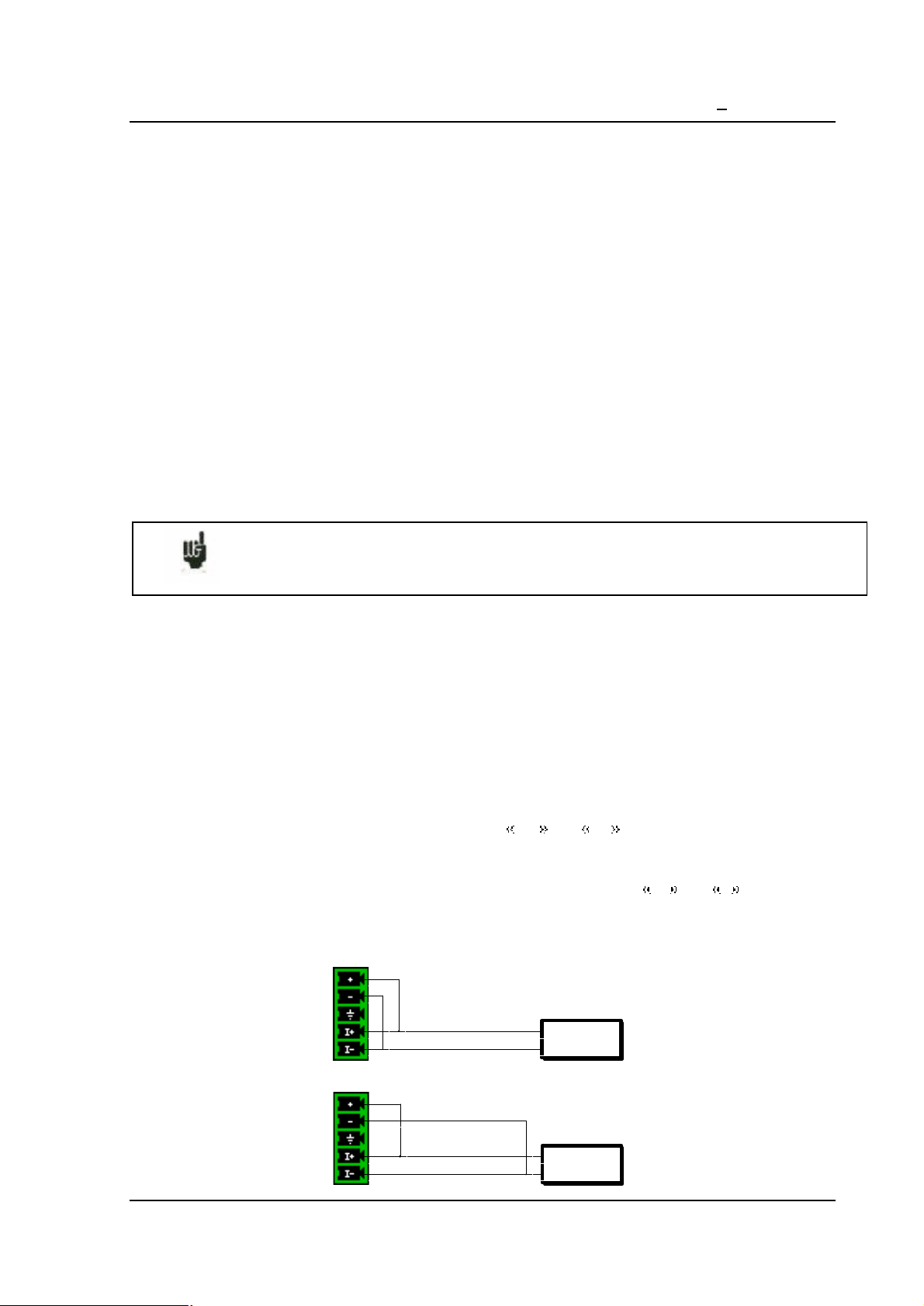
3.4.3.Measureoftemperature withaPT100
Availableonlywithanon-isolateddifferentialinputmodule.
ThePT100probemustbeconnectedtotheterminals I+ and I- (1mAcurrentgenerator
output).
ThevoltageproducedbythePT100mustbemeasuredwiththeteminals + and - withoneof
thefollowingscheme:2wires,3wiresor4wires. The4wiresmountingmakethemeasurement
independentoftheresistorvalueoftheline.
2wireswiring:
PT100
3wireswiring:
PT100
Page3.5
Page 26
3 Initialisation
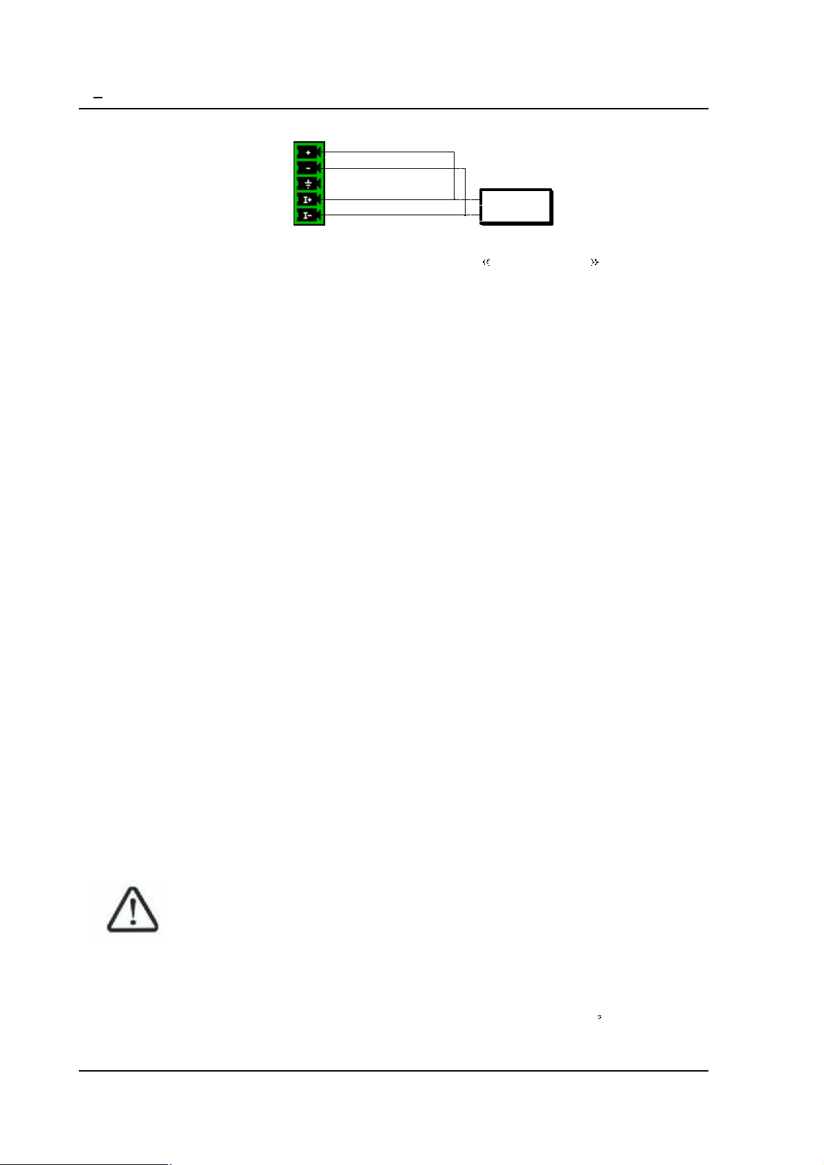
4wireswiring:
PT100
Youhavetochoosetheinputchanneltype2,3or4wiresinthe Channel setup function.
3.4.4.Measureof intensity
Isolatedinputmodule: itispossibletomeasureintensitieswithashunt betweentheredandblack
terminalsoftheconsideredinput.
Non-isolateddifferentialinputmodule:itispossibletomeasureintensitieswithashunt between
the"+"and"-"terminalsoftheconsideredinput.
Inthiscase,choosethe "Current"typeamongtheparametersoftheconsideredchannel.
Connectthemeasurecablestotheterminalsoftheshunt.
CollectedresultsaredirectlydisplayedinAmperesormilli-Amperesaccordingtotherangeofthe
consideredchannel.
3.4.5.Connectionofthegrounding
Formeasuringvery smallvoltages,problemsofspuriousvoltagesfromelectromagneticfieldsor
commonmodevoltagessbecomeallthemoreimportantthantheselectedsensibilityishigher.Thus,
itisimportantthattheouterwiringismadecorrectly.
Causesforsuchdifficultiesarevarious:
-uncertaintyaboutthetrueoriginsoftheperturbingvoltagesandimpedanceswhentheyare
generated
-uncertaintyaboutthespuriouscapacitancesofthecircuitsandwiring
-noaccesstotheinjectionpointofthecommonmodevoltageofthenetworkthatprovides
the signaltoregister
-non-conformityofsomeapplianceswiththecurrentnorms
-sometimesevenignoranceofthesourceimpedancesofthe signaltoregister
YOUSHOULDABIDEBYTHEFOLLOWINGINSTRUCTIONS
1/ The mechanicalground ofeveryappliances shouldbelinkedtothe earth.
Themechanicalgroundoftherecorderislinkedtotheearththroughthemainscable.
However,iftheotherappliancesinthe systemarenotequippedthesameway,you dbettergather
theirmechanicalgroundwiththegroundoftherecorder:youcanaccessitthroughaunionlinerat
therearoftheappliance.
Page3.6
Page 27

3 Initialisation
2/Ifthesourceofthe signaltorecordhasalowinternalimpedance,youwillhavetouse twisted
cables.Ifthe impedanceishigh,youwillhavetouse screenedcables.
3/Whengatheringthegroundingfromthevariouselementstothemeasurechain,you dbetter
checkthatthereisnodifferenceofpotentialinordertoavoidanyshort-circuit.Ifthereisanydoubt,
makeameasurewithavoltmeterwithalowcharge(1k forexample)betweentheterminals.
3.5.Routinemaintenance
Theordinarymaintenanceisonlyacleaningoftheoutsideoftheappliance.Anyotheroperation
requiresqualifiedpersonnel.
Unplugtheappliancebeforeanyintervention.
Donotletwaterflowintotheappliance,inordertoavoidanyelectricaldischarge.
Regularlycleantherecorderinrespectwiththeseinstructions:
-usewaterandsoaptocleanthefrontandrearbeards
-neveruseanyproductincludingbenzineoralcoholthatwoulddamagethescreen
printings
-wipewithasoftnon-plushycloth
-useananti-staticproducttocleanthescreen.
3.6.Calibrationoftheoffsets
Youcaneasilycalibratetheinputsoftherecorderfortheoffsetsofthevoltagesandofthe
thermocouples.
Todoso:
-maketheapplianceworkfor20minutes(outsidetemperature:20to25 C)
-for EVERYinputs,linkthered"+"terminaltotheblack"-"terminal
-validateeverychannels"ON"
-pressthekeyandselecttheline ElectronicCalibration andthenthe
menukey CalibrationOffset
Whenpressingthe Confirm menukey,youwilllaunchthecalibrationprocedurethatwilllast
about10minutes.
Page3.7
Page 28

3 Initialisation
3.7.Factoryadjustement
Youcaneasilyrecalltheadjustementmadeatthefactory,torepairapossibleerrorofthe
calibrationcoefficients:
-pressthekeyandselecttheline ElectronicCalibration andthenthe
menukey ReloadFactoryCoeff.
Whenpressingthe Confirm menukey,youwillreloadthecalibrationcoefficientsstoredatthe
factory.
Page3.8
Page 29

3 Initialisationandprecautionsofuse
ESCORT3008B-Page3.1
Page 30

4 Use
4.USE
Thischapterdescribesindetailstheactionsofeverykeysofthefront-sidekeyboard.
TheseactionsarealsoavailablewithamouseoranexternalkeyboardtypePC(seechapter
Presentation )
ThedetailsofkeysandtheirusesarethesameforeachrecorderESCORT3008B,ESCORT3016B
and ESCORT3004B.
Ifthisisnottrue,thekindofrecorderconcernedwillbewritteninthetext.
4.1. Mode key
Choiceofthefunctioningmodeoftherecorder:
DIRECT mode:real-timepaper-printingofthemeasured signals (ESCORT3008B
only)
-use:immediatewritingonpaper,long-term slowacquisition
-possibilities:complextriggeringofthewriting,actionaftertheendofthewriting,
simultaneousrecordingininternalmemoryoronafile
MEMORY mode:fastacquisitionininternalmemoryofthemeasured signals
-use:short-termfastacquisition(transitory)
-possibilities:complextriggeringofthewriting,actionaftertheendofthewriting,
simultaneousrecordingonfile
FRAME mode:fastacquisitionininternalmemoryofthemeasured signals
-use:short-termfastacquisition(transitory)forcaptureofnonrepetitiveevents
-possibilities:complextriggering,particularlyonoverrunofapre-recordedframe
fromachannel,actionaftertheendofthewriting, simultaneousrecordingonfile
FILE mode:fastacquisitiononinternalharddiskorUSBkeyofthemeasured signals
-use:long-termfastacquisition(onlylimitedbythe sizeofthememory)
-possibilities:complextriggering,actionaftertheendofthewriting,verybig
amountofdataofacquisition
Page 1
Page 31

4 Use
4.2. Help key
Displaysahelpwindowortheuser snotice.
Afterpressing Help ,pressinganyotherkeywilldisplaythehelpassociatedwithit.
Pressthe Help keyagaintoexit.
Ifamouseisconnectedtotherecorder,youcanalsodisplaytheuser snotice(requiresan
integratedPDF-reader,cannotbeusedwithoutamouse).
Page 2
Page 32

4 Use
4.3. Setup key
Generalconfigurationoftheappliance,controlofthealarmoutputs, TCP/IPnetworkaddress,
calibrationofthechannels,updatingoftheinternalsoftware.
Language:choiceofthelanguageusedbytheappliance
Screenshut-off: turnsofftheback-lightingoftheLCDscreen,adjustmentofthedelay
Configuration:initialisationoftheapplianceinitsdefaultconfiguration,saving/loadingin
internalROMmemory,oninternalharddiskorUSBkey,thermalpaperprinting
ATTENTION: youwillloosethecurrentconfiguration
AlarmA: useoftheAalarmoutput(relaycontact)
- Without:noconditioniscontrollingthecontact;itremainsalwaysopen
- Trigger:controlbyassociationoftheanalogicalorlogicalchannelsonseveral
thresholds(cf.chapterTriggering)
- Papererror:controlbylackofpaperoropeningofthedooroftheprinting
block (ESCORT3008Bonly)
Inanycase,thecontactis open iftheconditionis true.
Page 3
Page 33

4 Use
AlarmB: useoftheBalarmoutput(logical0-5Voutput)
- Without:noconditioniscontrollingtheoutput;itremainsalwayslow(0V)
- Trigger:controlbyassociationoftheanalogicalorlogicalchannelsonseveral
thresholds(cf.chapterTriggering)
- Papererror:controlbylackofpaperoropeningofthedooroftheprinting
block (ESCORT3008Bonly)
Inanycase,theoutputis low(0V) iftheconditionis true.
AlarmC: id.AlarmB
Datemodification:settingthehouranddatefortheappliance
Ethernet: modificationofthe TCP/IPaddressandoftheaddressmask
PositionMaxofbargraph:movingdirectionofthebargraphofeachchannelonthescreen
- Right:maximumvalueofthechannelontheright
- Left:maximumvalueofthechannelontheleft
Electricaladjustment: calibrationoftheoffsetsofthechannels,returntothefactory
adjustments
Softwareupdate: updatingoftheinternalsoftware(seechapterPresentation)
Thewindowatthebottomofthescreen shows:
-Thecurrent TCP/IPaddress
-Thenumberofthecurrentversionoftheinternal software
-Thenumberofdetectedchannels
Page 4
Page 34

4.4. Chart key
ESCORT3008Brecorderonly.
Definitionofeverycharacteristicsofthepaperprinting.
4 Use
Seechapter Directmode foradescriptionindetailsoftheparametersonthispage.
Page 5
Page 35

4 Use
4.5. Channelssetup key
Configurationofthechannels.Afterpressingthiskey,selectamodule,thenselectachannelto
accessitsparameters.
4.5.1.Analogicalchannels
Name: giveanametothechannel(max.26characters)
Type: choiceofthetypeofmeasuremadeonthisinput
-voltage,intensity,frequencyorthermocouple
-directorRMS
-valueofthe shuntinintensitymeasurement
-choiceofthetypeinthermocouple,compensation,unit
Filter: positioningafilterattheinlet
-10kHz,1kHz,100Hz,10Hzforanalogicalfilters
-1Hz,10s,100sor1000sfordigitalfilters
Function: makesitpossibletoassignamathematicalcalculationfunctiontotheconsidered
channel
- Without:nofunction.
- Changeunit: modifiestheunitofthemeasuresonthechannel;youcanthen
programacoupleofdotsX1,Y1andX2,Y2toachieveascaling
- Calculation: availablemathematicalfunctions,associatedparametersandunit
Page 6
Page 36

4 Use
RangeandZero: settingtherangeandthezeroofthechannel
Therangeisthemeasurethatcorrespondswiththetotalwidthofthescreenonwhichthechannelis
printed.
Thezero(orcentre,oroffset)isthecentralvalueofthemeasure.
Youcansettlepreciselythevalueoftherangeandofthezero,sothatyoucantakefullbenefitof
thewholewidthofthescreenorpaperoutput.
The RazZero keyallowsyoutofixthezerointhemiddleoftherange(analogicalzero).
NOTE:Whenusingamathematicalfunctionorascaling,thezeromatchesthezerointherequested
unit.
Position: positionofthezerointhescreenoronthepaper,from0upto100%
ThelowerpartoftheLCDscreen showsyouthemin.andmax.possiblevalues(limits)ofthe
measure,andthepositionofthezero.
Awarningmessageisdisplayedontherightwhentheprogrammedanalogicalthresholdsareout
thepossiblemeasurementrange.
Threshold 1:visualisationofthepositionofthetriggeringthreshold#1onscreenoronpaper
Threshold 2:id.forthreshold#2
Colour:allowsyoutomodifythecolouroftheprintingonscreen
LCDThickness: settlesthethicknessoftheprintingofthemeasureontheLCDscreenandon
thethermalpaper,from1upto8pixels
Page 7
Page 37

4 Use
4.5.2.Logicchannels
Changelogicchannels:choiceofthecolourandofthenameofthechannelonscreen
ValidEventMarkers:validationoftheacquisitionandoftheprintingofthelogicalchannels
Numberofmarkers: choiceofthenumberoflogicalchannels,from1upto16
HeightMark.: sizeofthedisplayandprintingzoneofthechannelsonthepaper
PositionMark.:positionofthelogicalchannelsonthescreenandonthepaper
Page 8
Page 38

4 Use
4.6. Channelon/off key
Choiceofthechannelsdisplayedonscreen,printedonpaperorrecordedinmemoryoronfile.
Afterpressingthiskey,choosetheinletcard(module)concernedwithF1(1stkeyontherightofthe
screen)andselectthechannelsyouwanttodisplayonthescreen,printonpaperorrecordin
internalmemoryoronfile.
Proceedthesamewaytovalidatethefunctionsbetweenchannels(theyareconsideredas
supplementarychannels).
Page 9
Page 39

4 Use
4.7. Display key
Real-timevisualisationofthemeasuresontheLCDscreenin1000dots.
Screen: configurationofthedisplayofmeasuresonscreen
-graphics F(t),graphics XY or digital displayofthemeasures
- Fullscreen displayofthemeasuresonly
- Modificationsdiagrams toorganisethedisplayonscreen(seechapter
Diagrams)
- Colour tocustomizethecoloursonthescreen
- vertical or horizontal sweeponscreen
-displayofthe nouns and limits (min-max)ofeachchannel.
4.7.1.DisplayF(t)(oscilloscopemode)
The F(t) displaymodeallowsreal-timevisualisationofthevalidatedchannelsonscreen,measures
withcursors,addingautomaticamplitudeandtimemeasurements,thensavingintofilesorprinting
onpaperoftheacquisitionafterstop.
Stop:freezesthemeasuresonscreeninordertoachievemeasurementswithcursors,
calculations,savingsorprintingsofthemeasuresonscreen(1000dots)inF(t)mode.
Youwillthenhaveaccessto:
- Restart torestartthesweep
Page10
Page 40

4 Use
- Timecursors todisplaytheverticalcursors(2)inordertomakemeasuresin
thedisplay;movethecursorsby selecting1or2thenturningthethumbwheel,or
clickonthecursorwiththemouseifitisconnected
- Voltagecursors todisplaythehorizontalcursors(2)tomakeamplitude
measuresonthedisplay;proceedasforthetimecursorstomovethem.Youvan
alsochangetherange/zerotoexpandandmoveyourmeasureonthescreen.
Timebase:changesthebaseofthesweepingtimeoftheF(t)display,from100 s/divupto
10mn/div;eachdivisionincludes100dots,i.e.asamplingfrequencyfrom1Mech/s(1 s)upto
0.16ech/s(6s).
InF(t)mode(oscilloscopemode),thesweepingisin triggered modefortime
bases<50ms/div,andin scrolling modeabove.
In triggered mode,the4followingparameterssetthetriggerofthedisplayedacquisition. These
parametersarenotavailablein scrolling mode:
Choice:choiceofthetriggeringchannel
Front:activefrontoftriggering
Level:verticalpositionofthetriggerbetween-100%and+100%
PositionDecl.:horizontalpositionofthetriggerbetween0and10divisions
In triggered mode,thepositionofthetriggerismarkedwitha smalltriangleontheselected
channel.
Validation:choiceofthedisplayedchannelsonscreen;identicalasthemainkey Valid.
channels
CalculationMath.:addingautomaticmeasurementsonscreen;click Add toaddameasure
onthescreenand Delete todeleteone;seechapter Mathematicalcalculations .
-#Param:choiceofthemeasureformodification
- Channel:choiceofthechannelonwhichyouwillassignthemeasurement
- Typeoffunction: Amplitude foramplitudemeasurements, Time fortime
measurementsor Calculation formeasurementsofaveragevaluesandeffective
valuesRMS
Page11
Page 41

4 Use
4.7.2.DisplayXY
The XY displaymodeallowsyoutodisplaythevalidatedchannelsinrealtimeonscreen,one
versustheothers.
Oneofthechannelsdefinestheextensiononthehorizontalaxis;theotherchannelsdefinethedots
ontheverticalaxis.
Gridpattern:tocustomisethegridpatternoftheXYdisplay
Youcanselect,eitherapredefinedgridpatternwithselectionofthecolour,eitheracustomised
gridpattern(copiedfromanUSBkeyorftptotheharddisk)
ThisBMPfile sizeis640*640pixelswith24colours,thepredefinedgrid(gridxy.bmp)isinthe
basedirectoryoftheharddisk.
Youcanuse paint (from Microsoft)orafreesoftware(paint.NET,gimpwordetc..)
tocreatetheBMPfile.
Withpaintsoftware,tocreatealineyoumustgivethetwopointscoordinates.
Thesescoordinatesaredisplayedonbottomleftcornerofthewindow.
Pointorvector: displaythepointorthelinebetweensuccessivepoints .Ifthechannel
frequencyishigherthanthedisplaypointfrequency(0.1Hz)youcanhaveafalsedisplay
Xchannel:choiceofthechannelonthehorizontalaxis(sweep)
Ychannel:
- One:onlyonewayontheverticalaxis;choiceofthischannelonthefollowing
parameter
- Several:accesstothevalidationofthechannelsonthefollowingparameter
4.7.3.Digitaldisplay
The Digital displaymodeallowsyoutodisplaythedigitalvaluesofthevalidatedchannelsinreal
timeonthescreen.
Noactionispossibleinthismode.
4.8.Directionkeys
Theymovethereversevideozoneontotheparametertomodify.
Youcanmodifytheparameterswiththethumbwheel,withamouseifitisconnected,orwithan
externalkeyboard.
Page12
Page 42

4 Use
4.9. Trigger key
Programmingthestartandstopconditionsofthepaperprintingin ESCORT3008BDirectmode,
theacquisitionofthechannelsin Memory,FileandGoNogomodes.
Choiceoftheactionsafteracquisitionorprintingandvalidationofthesavinginrealtime.
Theprogrammingofthetriggersisdifferentaccordingtothecurrentmode(Direct,Memory,
GoNogoorFile).
Seethechaptercorrespondingwiththecurrentmodeforamoredetaileddescription.
Page13
Page 43

4 Use
4.10. Replay key
DisplayonscreenoftheacquisitionsavailableininternalmemoryorinfilesonharddiskorUSB
key.
Thisfunctionhasthesamecommandsasthe Display function.
Theonlydifferenceisthe BlocksandFiles commandthatallowsyoutoselectthememory
block(zoneintheinternalmemorydividedinblocks)orthefiletodisplay.
BlocksandFiles:
- Numberblock:numberofthememoryblocktodisplay
- Loadfile:choiceofthefiletodisplay
- Loadconfiguration:copyoftheconfigurationoftheacquisitionbeingdisplayed
intothecurrentconfiguration(validatedchannels,ranges )
- SaveDisk:savingthecurrentdisplayintoafile
- Reference:comparisonofblocksversusareferenceblock(Memorymode);the
tracesofthereferenceblockare shownindots
Page14
Page 44

4 Use
Whenthe sizeoftheacquisitiontodisplayisbig,collectinganddisplayingthedotsmay
belong.
Displayingisthenachievedin2phases:
-aquickphasethatdisplaystheenvelopeoftheacquisition:somedotsmaynotappear
-aphasewhereallthedotsoftheacquisitionaredisplayed:anassessmentofthepercentageof
advanceisdisplayedatthebottomofthescreen.
4.11. Start/Stop key
Thiskeyhasvariouseffectsaccordingtothecurrentmodeoftheappliance.
ESCORT3008BDirect mode:launchestheprintingonpaperifitstriggeringisinmanualstart;
else,setstheapplianceinwaitmodeforthetriggering Start condition.
Memory mode:launchestheacquisitionininternalmemoryandsetstheapplianceinwait
modeforthetriggering Start condition.
GoNogo mode:launchestheacquisitionininternalmemoryandsetstheapplianceinwaitmode
forthetriggering Start condition.
File mode:launchestheacquisitiononfileandsetstheapplianceinwaitmodeforthetriggering
Start condition.
Inanycase,tostoprecordingbeforethetriggering Stop condition, youonlyhavetopressthesame
key Start/Stop onceagain.
In Memory, GoNogo or File modes,theappliancesswitchesautomaticallytodisplayof
thecurrentacquisition.
Atthetopleftofthescreen,itwillthenappear:
-thenumberofthecurrentblockifrequired
-thecurrentsamplingrate
-thestatusoftheacquisition(waitingtriggeringstart,proceedxx%, )
-theopeningofasavingfileifrequired
-abargraphwhereyoucanrecognisethepercentageofachievedacquisitionand
thepercentageofdisplayedacquisition.
Page15
Page 45

4 Use
4.12.Paper-feedkey
ESCORT3008Bpaper-feedaslongasyoupressthekey.
Page16
Page 46

5 Diagrams
5.DIAGRAMS
Diagramsarethepartitionofthescreenorofthewidthofthepapersheetsinzonesofprintingor
displayinginordertogatherorseparatechannelsandimprovethelegibilityoftheacquisitions.
Youcanaccessthisconfigurationwiththe ModificationDiagrams keyfrom:
- Paper key,parameter Reticule
- Directvisualisation key,parameter Screen
- Memoryoutput ,parameter Screen
Theapplianceswitchesautomaticallyto Directvisualisation toshowyouyourorganisation:
NumberDiagram:numberofdivisionsofthescreenorofthepaperuptomaximum12
V.Logseparated:printsordisplaysofthelogicalchannelssuperimposedtothediagramsorin
aseparatediagram
HeightV.Log: sizefordisplayingthelogicalchannels,from3upto250mm
Page 1
Page 47

5 Diagrams
PositionV.Log:positionofthedisplayofthelogicalchannelsaboveorbelowthediagramsof
theanalogicalchannels
Validate:validationofthepreviousparameters(Numberdiagrams,heightandpositionofthe
logicalchannels)inordertotakethemodificationsintoaccount
Positionofthechannels:placeofthechannelsinthediagrams;selectthechannelyouwant
andpressthearrowstomoveit
ChangeDiagrams:modificationofthe sizeofeachdiagram;selectthechannelyouwantand
enteritsstartandheightinmm.
Don tforgettovalidateyourmodificationstohavethemtakenintoaccount
Afterselectionofthenumberofdiagramsorvalidationofthelogicalchannels,
press Validate ;theappliancedispatchesthediagramsonthescreen(andalso
onthepaper)automaticallyinequalsizes
5.1.Positionsofthechannels
Pressthe Positionofthechannels keytodispatchthechannelsinthediagrams.
Page 2
Page 48

Selectthechanneltomove,thenusethe2arrowstomoveitupwardordownward.
5.2.Changediagrams
Pressthe ChangeDiagrams keytochangethe sizeofeachdiagram.
5 Diagrams
Selectthediagramtochange,thenadjustitspositionwith Start andits sizewith Height .
Don tforgettovalidateyourmodificationstohavethemtakenintoaccount
Page 3
Page 49

6.TRIGGERS
Thischapterdescribesthetriggersavailableinthisappliance.
Theyareusedby:
- Setup key,parameters AlarmA,Band C
- Trigger key,parameters Start and Stop
6 Triggers
Analogical/Logicalchannels:triggeringfromanalogicalorlogicalchannels(eventmarks)
Single/Severalthresholds:
-triggeringfromonlyonechannelandonlyonethreshold
-orcomplextriggeringfromseveralchannelsand severalthresholds;seedescription
below.
Thiscomplextriggeringisonlypossiblewithanalogicalchannels.
Page 1
Page 50

6 Triggers
6.1.Triggering withanalogicalchannels
Afterselectionofthetriggeringwithanalogicalchannels,thefollowinglineonscreenwillallow
youtosetparametersforthetriggeringstartcondition.Itwilldependontheselectionofonlyone
thresholdorofseveralthresholds.
6.1.1.Singlethreshold
Channel:selectionofthechannelonwhichthetriggeringstartthresholdisassigned
Threshold1/Threshold 2:selectionofthethresholdtoparameter;eachchannelistestedwith
twothresholds.Youcan,forexample,programa startconditiononthechannelA1andthe
Threshold1,andastopconditiononthesamechannelA1andthe Threshold2.
Front:selectionoftheactivefrontforthethreshold
Forexample,theconditionA1(s1):0.000Vbecomes TRUEwhenthechannelA1turns
higherthan0V.
Thresholdvalue:valueoftheselectedthresholdinpercentageandtruevalue(takinginto
accountthecurrentunitandscaleintheconfigurationoftheselectedchannel)
Fine/Coarse:selectionofthefineorcoarsesettingoftheselectedthreshold
Page 2
Page 51

6 Triggers
6.1.2.Severalthresholds
Afterselectionofatriggeronseveralchannelsandthresholds,a Call keyallowsyouto
programtheconditionforacomplextrigger.
OneofThresholds(or): thefirstconditionsachievedvalidatesthetrigger
AllThresholds(and): everyconditionsmustbeachieved simultaneouslytovalidatethetrigger
Slope(or): triggeringaccordingtothe slopeofthe signals;thefirstconditionachievedvalidates
thetrigger
Youwillthenbeabletoadd,deleteormodifyanyconditionofthetriggerbyselectingoneofthe
conditions.
Page 3
Page 52

6 Triggers
6.1.3.Triggeraccordingtothresholds
Example:thetriggeraboveis
Triggeringif
ChannelA1increasingandequaltothethresholdS1,value0.000VOR
ChannelA2increasingandequaltothethresholdS1,value0.500VOR
ChannelA2increasingandequaltothethresholdS2,value0.500VOR
ChannelA3decreasingandequaltothethresholdS1,value0.500V
ThesameanalysisisworthfortheANDtrigger(everythresholds).
Page 4
Page 53

6.1.4.Triggeraccordingtotheslope
6 Triggers
Example:thetriggeraboveis
Triggeringif
ChannelA1increasingwithapositive slope:2.000Vona1speriodOR
ChannelA2increasingwithapositive slope:0.500Vona1speriodOR
ChannelA3increasingwithapositive slope:0.500Vona1speriod
Page 5
Page 54

6 Triggers
6.2.Triggering withlogicalchannels
Afterselectionofthetriggeringwithanalogicalchannels,thefollowinglineonscreenwillallow
youtoparameterthetriggeringcondition.
The16logicalchannelscanbeusedinthetriggeringinstruction:
-eitheractiveinstate0(lowerthan1.6volt)
-oractiveinstate1(higherthan4.0volts)
-ornotused
Page 6
Page 55

7 Mathematicalcalculations
7.MATHEMATICALCALCULATIONS
Youcanmakemathematicalcalculationsonachievedacquisitions.
Youcanaccessthemwiththe Display functionandthe Replay functionifanacquisitionis
displayedonscreen.
7.1.Definitions
Pressthe Math key.
Add: addamathematicalcalculation
Remove:deleteoneofthedisplayedmathematicalcalculations
#Param:selectionofthenumberofthedisplayedcalculationformodification
Channel: selectionofthechannelonwhichtheselectedcalculationof #param willbe
made
FunctionType: typeofcalculationmadeintheselectedcalculationof #param
Page 1
Page 56

7 Mathematicalcalculations
RisetimeFalltim
e
Function: selectionofthecalculationfunctionmadeintheselectedcalculationof #Param
Youcanchooseamong20differentmathematicalcalculationsin3categories:
- Amplitude:minvalues,maxvalues,peaktopeak,base,highest,amplitude,overshoots
- Time:frequency,period,increasingtime,decreasingtime,positivewidths,negative
widths,positiveandnegativedutyfactors
- Calculation:averagevalues,cyclicaverage,cyclicRMSandeffectiveRMS
Youcandisplayupto 5simultaneouscalculations onscreen.
Thedisplayismadeinrectanglesabovethediagramswherearealsospecified:
-thenumberofthechannel(withitscolour)
-thetypeofcalculation
-thevalueofthecalculation
In Display function,thecalculationsaremadeinrealtimeandthedisplayisupdatedevery300
ms.
Thecalculationismadeonthe1000dotsdisplayedonscreen. Thus,thetimeresolutionis0.1%.
Thecalculationscanconcerneverychannels.However,youcannotassigncalculations:
-onthesupplementarychannelsthatarefunctionsofotherchannels
(exampleF3=A1+B2)
-ifthechannelshavebeenrecorded(validationON/OFF)
7.2.Typesofcalculations
Max
High
90%Ampl
10%Amp
Lo
w
l
Min
Amp
P
l
eak_peak
Explicativescheme
Page 2
Math.
Functions
Calculation Remarks
Page 57

7 Mathematicalcalculations
Period
N
Minimum
Maximum
Peak_Peak
Low
High
Amplitude
Thelowestnegative
voltage
Thehighestpositive
voltage
Max Min
Themostfrequent
value belowthe
centre
Themostfrequent
valueabovethe
centre
High Low
T1 T
T1 T
Positive
overshoot
Negative
overshoot
Frequency
Period
HighMax
Amplitude
MinLow
Amplitude
1
100
100
Averagefrequency
Average durationof
periodfullNofDuration
atotalcycle,
calculatedonas
many periodsas
possible
T1=10%Amplitude
Risetime
2
T2=90%Amplitude
Increasingtime= T2 T1
T1=90%Amplitude
Falltime
2
T2=10%Amplitude
Decreasingtime= T2 T1
Page 3
Page 58

7 Mathematicalcalculations
Positivepulse
width
Negativepulse
width
Positivecycle
time
Negativecycle
time
Average
Measureofthedurationofthe
1stpositiveimpulsion.Madeat
50%oftheamplitude
Measureofthedurationofthe
1stnegativeimpulsion.Madeat
50%oftheamplitude
impulsionpositiveofduration
period
impulsionnegativeofduration
p iode
N
1
Moy
N
i
V
i
1
N:totalnumberofdots
Calculationonthe
wholegraphic
window
Cyclicaverage
RMS
CyclicalRMS
2
N
NN
12
V
i
1
Ni
Moy
1
N2-N1:numberofdotsbetween
completeperiods
N
RMS
RMS
1
N
1
NN
i
V
1
N
)(
12
2
i
2
V
1
Ni
i
2
Calculationonas
many periodsas
possible
Calculationonthe
wholegraphic
window
Page 4
Page 59

8 Directmode
8DIRECTMODE
Thischapterdescribesthe Direct modeofthe ESCORT3008Brecorder,designedtoplotinreal
timeonthermalpaperthemeasuresachievedonthechannels.
Thismodedoesnotexiston ESCORT3016Band ESCORT3004B.
Youcantriggerthestartandstopoftheplottingundervariousconditions.
Youcanactivateasimultaneoussavingofthemeasurementsinaninternalmemoryorinafile.
8.1.Configurationoftheplotting
Pressthe Chart key.
Definitionofeverycharacteristicsofthepaperplotting.
Page 1
Page 60

8 Directmode
Mode: choiceoftheprintingmode
- F(t):printingagraphversusthetime
- Numeric:printingdigitalvaluesofthemeasuresinatable
Paperspeed: printingspeed
-internallyratedfeedfrom1mm/hupto200mm/s
-externallyratedfeedthroughthelogicalchannel16
GridPattern: definitionofthegridpatternplottedonthepaper
-none,every5mm,10mmorwithanintegernumberofdivisions
-fineorwide,i.e.withorwithoutsubdivisions
-accesstothe ChangeDiagrams toorganisethepresentationofthechannels
Title:givingatitle(max.124characters)forprinting.Itwillappearatthetopofthe
papersheet.
Time:typeoftimereference,printedatthebeginningoftheplottingandwithevery
annotation
-absolute:real-timehouranddate
-relative:settingtozeroatthebeginningoftheplotting,printingtheelapsedtime
onthepaper(seechapter Diagrams)
aftereachnewannotation.
Boundary:possibilitytowritethelimitsofeachchannel(min-max)andthepositionof
zeroattheendoftheplotting
Annotation:possibilitytohaveannotationswhileprinting
-no,atthebeginningoftheplotting,onanalarmoronalengthofpaper
-madeofthename,thenumber,thecurrentvalueortherangeofthechannels
WriteMessage:youcanalsowriteatextdirectlyonthepaper
-afterenteringyourtext,pressthe Write key:thetextwillbeimmediately
plottedonthepaper
-iftheplottinghasbegun,itwillbepausedandwillstartagainwhenthelineis
written.
PlotaBMPfile:youcanwriteafileunderBMPformat(bitmapwindows). TheBMP
filemustbe singlecolour(height2000pixelsmaximum).Themustbeontheharddisk,
andcanbecopiedwithanUSBkeyorviaftplink
.
Page 2
Page 61

8.2.Triggeringplotting
Pressthe Trigger key.
Programmingthestartandstopconditionsoftheplotting.
Selectionoftheactionsaftertheplottingandvalidationofthesavinginrealtime.
8 Directmode
Mode: selectioniftheprintingmode
- F(t):printingagraphversusthetime
- Numeric:printingdigitalvaluesofthemeasurementsinatable
Paperspeed: printingspeed
- internally ratedfeed from1mm/hupto200mm/s
- externally ratedfeedthroughthe logicalchannel16
SpeedbeforeTrigger:printingspeed before the starttrigger;possibleifthestarttrigger
isnotManual
Start:conditionforstartingtheplotting
- Manual: withthe Record key
- Trigger:withanassociationoftheanalogicalorlogicalchannels
seeChapter6Trigger
- Waitfor:afteradelayorataprecisedateandtime
Page 3
Page 62

8 Directmode
Stop:conditionforstoppingtheplotting
- Manual: withthe Record key
- Trigger:withanassociationoftheanalogicalorlogicalchannels
- Waitfor :afteradelayorataprecisedateandtime
- Paperlength:afterwritingaprogrammedlengthofpaper
Afterendofplot:actionaftertheendoftheplotting;onlypossibleifthestartandstop
triggersarenotManual
- Stop: noaction
- Rearm:waitingforthestarttrigger
- ChangeSetup.:loadingaconfigurationandwaitingforthestarttrigger
SaveData:simultaneoussavingofthemeasurementsininternalmemoryoronafile
- Nosave:nosimultaneoussaving
- Memory:recordingininternalmemory
- File:recordingonafile
seeChapter6Trigger
- Acquisitionperiod:samplingspeedofthechannels
- Blocks:dividingtheinternalmemoryintoblocks
- Filename:placeandnameofthesavingfile
- Acquisitionperiod:samplingspeedofthechannels
Seechapter Filemode toknowthelimitationsofthefilerecording
Trigger:conditionforstoppingthe simultaneoussavingininternalmemoryonly
- Direct:thesameasforpaperprinting
- Manual:withthe Record key
- Trigger:withanassociationoftheanalogicalorlogicalchannels
seeChapter Trigger
- Pre-triggering:positionofthetriggerinthememory(intheblock)
Following:actionsaftertheendofthe simultaneousacquisitionintothe memory
- Saveonfile:savingtheacquisitionintoafile
- Plot:writingthe simultaneousacquisitionintothememory
- Rearm.:reloadingthewriting;waitingforthestartconditionagain
Ifaspeedbeforestarthasbeenprogrammed,thepaperwillbefedatthisrate
whilewaitingthetrigger.
Theusercanurgethetriggeratanytimebypressingthe "Start/Stop"keyagain
whilewaitingforthestart
Page 4
Whileplotting,pressingthiskeywillstoptheplotting
Incaseofpowerfailurewhileplotting,therecorderwillstartagaininthesame
status(waitingorwriting)
Page 63

8 Directmode
8.3.Rearmamentoftheplotting
Inrearm.mode,waitingforthestartoftheplottingisautomaticallyreloadedwhenthestop
conditionsarouse.
Tointerruptthecycle,youonlyhavetourgethestopoftheplottingbypressingthe "Start/Stop"
keywhileplotting.
8.4.Writingdata
Atthebeginningofeachplottingarewrittenthedate,thehour,theprogrammedtitleatthetopof
thepapersheet.
Thenumberofeachchanneliswrittenontheplotting.
8.5.Exampleofplottingprogram
Wewouldliketotriggertheplottingofthechannel1whenthechannels3and4arebothabove
50%ofthefullscale.
Beforetriggering,theplottingwillbemadeatlowrate(5mm/s).
Aftertriggering,therecorderwilldraw50cmpaperat50mm/s,thentheconfiguration"Config3"
willbeloaded.
Program:
in DIRECT modewiththe MODE key
Chart key:
Trigger key
Here,youcandefineallthatconcernstheplottingonpaper
Inourcase,only1diagramon250mm
Here,youcouldgivetheplottinganameandcallthewritingofannotations.
Paperspeed :50mm/s
Start : Trigger
- Speedbeforetrigger :5mm/s
- Analogicchannels
- Severalthresholds
Definitionofthestartconditiononthefollowingline:
Call :
- Everythresholds(AND)
-followingline: addathreshold
-channelA3,threshold1,increasingfront,Add
-adjustthethreshold1at50%
- addathreshold
-channelA4,threshold1,increasingfront,Add
-adjustthethreshold1at50%
Stop :Paperlength
-paperlength:500mm
Afterendofplot :ChangeConfig.
- Configuration :inourcase:"3"
SaveData :inourexample,wewillleave no
Channelson/off key
Page 5
Page 64

8 Directmode
-moduleA
-ChannelA1 ON
Channelssetup key
-selecttherangeandthezerosothatthechanneliscentredonthepaper
Recording:
Pressthe "Start/Stop"key.
Thewritingbeginsata5mm/srateandwaitsforthetriggerstartcondition.
WhenbothchannelsA3andA4havereachedtheprogrammedthresholdonincreasing,thetrigger
startisvalidated.
Thewritingturnstoa50mm/srateandkeepson50cm,thus10s.
Afterthese10seconds,itturnsdirectlytotheconfiguration3.
Whenthenewconfigurationisready,therecorderproceedsasiftheuserhadpressedthe
"Start/Stop"key.
Page 6
Page 65

9 Memorymode
9.MEMORYMODE
Thischapterdescribesthe Memory modedesignedtorecordinrealtimeintotheinternalmemory
themeasuresachievedonthechannels.
Youcantriggerthestartandstopoftheplottingundervariousconditions.
Youcanactivateasimultaneoussavingofthemeasurementsinaninternalmemoryorinafile.
9.1.Configurationandtriggeringoftheacquisition
Pressthe Trigger key.
Definitionoftheacquisitionintointernalmemory.
SampleRate:samplingrateofthechannels
- internally ratedfrom 1 sto20min
- externally ratedthroughthe logicalchannel16
Blocks:divisionoftheinternalmemoryintoblocks
-1,2,4,8,16,32,64or128
Page 1
Page 66

9 Memorymode
- RazBlocks:deletingalltheblocks:thecurrentblockisthe#1block
Start:startconditionoftheacquisition
- Manual: withtheF2key Urgetriggering
- Trigger:withanassociationoftheanalogicalorlogicalchannels-seeChapter6
Trigger
- Waitingfor:afteradelayorataprecisedateandtime
- Automatic:immediate;automaticstopwhentheblockisfull
Pre-triggering:definitionofthepositionofthestarttriggerintheacquisition
-pre-triggerandpost-triggeroftheacquisition(beforeorafterStart);andifthetrigger
isallowedduringpretriggeringtime
Stop:stopconditionoftheacquisition
- Automatic: whentheblockisfull
- Trigger:withanassociationoftheanalogicalorlogicalchannels-seeChapter6
Trigger
Triggermode DoubleTrigger:seebelow
Real-timeSaving: simultaneousrecordingoftheacquisitionintoafile
-placeandnameofthesavingfile
-maximumlengthofthefile
Impossible isdisplayedwhenthesavingcapabilitiesareoverrun:reducethe
samplingrateorthenumberofchannels
Seechapter Filemode toknowthelimitationsofthefilerecording
Following:actionsaftertheendoftheacquisition
- Saveonfile:savingtheacquisitionintoafileifthereal-timesavingisnotvalidated
(orisimpossible)
- Plot:plottingtheacquisition
- Stop: noaction
- Rearm:waitingforthestartcondition
- Changesetup:loadingaconfigurationandwaitingforthestarttrigger
9.2.Samplingperiod
Whenthefrequencyoftheinput signalsistoohightorecordtheminDirectmode,youmustputthe
measured signalsintomemoryatahighacquisitionrate:thisisthe Memorymode
Samplingconsistsinreadingtheinstantvalueofa signalatregulartimeintervals:eachofthese
valuesisstoredinamemory.
Page 2
Page 67

9 Memorymode
Sothattheacquisitionofaperiodic signalisconvenient,youshouldselectasamplingperiodthatis
compatiblewiththefrequencyofthe signalsattheinputterminalsoftherecorder.
A10-dot-per-signal-periodaccuracyisminimumforaconvenientplotting
9.3.Internalmemory,blocks
Youcandividetheavailablememoryoftherecorderintoblocksthatwillbefilledoneafterthe
otherateachacquisition.
TheamountofdataofacquisitionisworthN/(B*V)
N=totalmemory
B=numberofblocks
V=numberofchannelstocollect
Example:memory:32Mbytes,16blocksand3channels"ON";youwillhave
N=32,554,432/(16*3)=699,050bytes/channel
Anynewacquisitionwillbeplacedautomaticallyintothefirstfreeblockavailable(inincreasing
sense).
Wheneveryblocksarefull,anewacquisitionwillshiftthepreviousblockNintotheblockN-1;the
1stblockwillbelost.
Thenewacquisitionwillthentaketheplaceofthelastblock.
9.4.Triggeringposition
Theacquisitionintoamemoryblockisbasedonthe systemofthe rotarymemory :
-thememorystartsfillingfromthestartcondition
-thememorykeepsonfillingaslongasthestopconditionisnotvalid;ifthememoryis
full,thefillingrestartsfromthebeginningofthememoryzone(block)
Thus,thememoryblockalwayscontainstheNlastsamples.
Theusercanchoosethemomentwhenthesamplesinthememorywillbefrozen:todoso,hewill
defineadelaybetweenthetriggeringmomentandthebeginningoftheeffectivetransferinto
memory.
Thisdelaycanbepositiveornegative. Thesamplesinmemorycanthusbeeitherbeforeorafteror
onboth sidesofthetriggeringmoment.
Wecanalsonotinhibitthetriggerduringthepretriggerphase:thisallowtotestthetrigger
conditionduringthepretriggerphaseandmakethetriggerfunctionevenifthepretriggertimeisn t
passed.
MEMORY
MEMORY
TRIGGERING
TRIGGERING
-50 %
MEMORYSTART
MEMORYSTART
+50 %
Page 3
Page 68

9 Memorymode
Transfertomemorywitha-50%delayTransfertomemorywitha+50%delay
relativelytothebeginningofthememoryrelativelytothebeginningofthememory
9.5.DoubleTriggermode
Inthismode,youwilluseastarttriggerandastoptrigger.
Youwillthusrecordthemeasurementsbetweenthosetwotriggers.
Theacquisitionwillautomaticallystop:
-whenthestopconditionisvalid
-orwhenthememoryblockisfull
Aninformationwindowwillsummarisethegeneralconfigurationoftheacquisition:
-channelsandfunctionsbetweenthechannelsvalidatedfortheacquisition
-numberofdotsperchannel(accordingtothenumberofblocks)
-totalacquisitiontime(accordingtotheacquisitionrate)
-positionofthetrigger(accordingtothepre-triggering)
9.6.Recording
Youlaunchthedataacquisitionbypressingthe Start/Stop key.
Itwillappearatthetopleftofthescreen:
-thenumberofthecurrentblockifrequired
-thecurrentsamplingrate
-thestatusoftheacquisition(waitingfortriggering,fillingxx% )
-theopeningofasavingfileifrequired
-abargraphwhereyoucanrecognisethepercentageofachievedacquisitionandthe
percentageofdisplayedacquisition.
ThemenukeyF1 Stop allowsyoutostopthecurrentacquisition.
Iftheacquisitiontimeoftherecordislessthan2minutes,thewholeacquisitionwill
bedisplayed.Youwon tbeabletoexitthispagethen:theacquisitionmustbestopped
beforeyoucanchangeofmenu.
Page 4
Page 69

9 Memorymode
Forlongeracquisitiontimes,youcanzoomonaportionofthedataorchangethepage.
Afterchangingthemenupage,youcangobacktotheacquisitionbypressingthe
"Start/Stop"key.
Page 5
Page 70

9 Memorymode
Supplementarymenukeys:
Display:
Total:thewholedatamemoryisdisplayedandupdatedduringtheacquisition.
Partial:onlyapartofthedatamemoryisdisplayed;thedisplayisfrozen;only
thebargraphandthepercentageofachievedacquisitionletyouknowthestatus
oftheacquisition;youhavethenaccesstothetimeandzoomcursors.
Youcannotdisplayanotherblockthanthecurrentone.Youcannotplotorsavetofile
theacquisitionaslongasitisnotover.
Attheendoftheacquisitionprocess,theapplianceswitchesautomaticallytomemorydisplay
function Replay .
Page 6
Page 71

9.7.Memoryoutput
Displayoftheacquisitionsavailableintheinternalmemoryorinfiles.
Possibilitytolaunchthepaperprintingoftheacquisitions.
9 Memorymode
Blocksandfiles:choiceofthememoryblockorofthefiletodisplay;ifthereisnovalid
block,theonlyexistingmenukeyis Loadfile .
Screen:typeofdisplay,diagrams;seechapter Use
Timecursor:verticalcursors,zoom;seechapter Use
Voltagecursor:horizontalcursors;seechapter Use
Fullpage:displayofthewholedatamemory
ChannelOn/Off:validationofthechannelsON/OFF
Math. calculation:addingautomaticmeasurementsonthescreen; seechapter Use
Setupplotting:configurationoftheplottingoftheacquisition; Launchplotting key
Atthetopleftofthescreen,itwillthenappear:
Page 7
Page 72

9 Memorymode
-thenumberofthedisplayedblock
-thesamplingrate
-thedateofthetrigger
-thenumberofdotsperchannelinthisblock
-abargraphwherethefillingpercentageoftheblockandthepositionofthe
triggeraredisplayed.
Page 8
Page 73

10 Go/Nogomode
10.GO/NOGOMODE
Thischapterdescribesthe Go/NogoMode designedforthereal-timerecordingintotheinternal
memorythemeasuresachievedonthechannels.
Youcantriggertheacquisitionundervariousconditions.Youcan stop itwhenmeasuresexceeda
previousacquisitiondefinedasaFrame.
Youcanactivateasimultaneoussavingofthemeasuresonafile.
10.1.Configurationandtriggeringoftheacquisition
Pressthe Trigger key.
Definitionoftheacquisitionintointernalmemorywithframe.
ChannelsforGo/Nogo:channelstocomparetotheframe;accesstothedefinitionoftheframe
Page 1
Page 74

10 Go/Nogomode
Samplerate:samplingrateofthechannels
- internally ratedfrom 1 sto20min
- externally ratedthroughthe logicalchannel16
Blocks:divisionoftheinternalmemoryintoblocks
-1,2,4,8,16,32,64or128
- RazBlocks:deletingalltheblocks:thecurrentblockisthe#1block
Start:startconditionoftheacquisition
- Manual: withtheF2key Urgetriggering
- Trigger:withanassociationoftheanalogicalorlogicalchannels-seeChapter6
Trigger
- Waitingfor:afteradelayorataprecisedateandtime
- Automatic:immediate;automaticstopwhentheblockisfull
Pre-triggering:definitionofthepositionofthestarttriggerintheacquisition
-pre-triggerandpost-triggeroftheacquisition(beforeorafterStart);seechapter
MemoryMode
Real-timeSaving: simultaneousrecordingoftheacquisitionintoafile
-placeandnameofthesavingfile
-maximumlengthofthefile
Impossible isdisplayedwhenthesavingcapabilitiesareoverrun:reducethe
samplingrateorthenumberofchannels
Seechapter Filemode toknowthelimitationsofthefilerecording
Following:actionsaftertheendoftheacquisition
- Saveonfile:savingtheacquisitionintoafileifthereal-timesavingisnotvalidated
(orisimpossible)
- Plot:plottingtheacquisition
- Stop: noaction
- Rearm.:waitingforthestartcondition
- ChangeSetup:loadingaconfigurationandwaitingforthestarttrigger
10.2.Creationoftheframe
Makeanormalacquisitionordisplayapreviouslyrecordedfilewiththefunction Memory
output .
Inthepage Trigger ,selecttheparameter ChannelsforGo/Nogo then Visualizethe
frame then Modify .
Theappliancewillthendisplaythecurrentframe.Itappearsas2curves(aminandamaxcurve)
aroundthechannel selectedasareferencefortheframe.
Page 2
Page 75

Bothcurveshavebeensavedinnon-volatileRAMinternalmemory.
10 Go/Nogomode
Return:returnstothepreviouspage,theframewon tbechanged
Blocknumber:allowsyoutoselectthereferenceblock
Channel:allowsyoutoselectthereferencechannel
DX and DY:allowyoutoplotthe2curvesminandmax
Begin and End:limitsofthememoryspaceusedforthetriggerstoptest
Save:assoonastheframeiscorrect,youcansaveitintoROMinternalmemory.
Youcannotsaveaframeonafile. Tokeepaframeonafile,savetheblockandthe
channelthatwillallowyoutorecreatetheframeforanewuse.
Page 3
Page 76

10 Go/Nogomode
10.3.Useoftheframe
Thecomparisonwiththeframeisusedtostoptheacquisition. Thiscomparisonwillbemadeonthe
ChannelsforGo/Nogo selectedinthe Trigger page.
Theinformationwindowatthebottomofthe Trigger pagesummarisesthegeneral
configurationoftheacquisition:
-channelsandfunctionsbetweenchannelsvalidatedfortheacquisition
-channelsandfunctionsbetweenchannelscomparedwiththeframe
-numberofdotsperchannel(accordingtothenumberofblocks)
-totalacquisitiontime(accordingtotheacquisitionrate)
-positionofthetrigger(accordingtothepre-triggering)
Thecomparisonwiththeframecanonlybemadewhenthechannelshavebeen
validatedfortheacquisition.
Anerrormessagewilldisplaywhenyouhaveselected ChannelsforGo/Nogo that
havenotbeenvalidated(ON).
Theacquisitionismadeaspreviously(seechapter Memorymode).
Whenthememoryblockisfull,theappliancewillcheckthateverycollecteddotsontheframe
channelsarethe2minandmaxreferencecurvesoftheframe.
Ifeverydotsarewithintheframe,theacquisitionwillstartagain(inthesameblock). Else,the
acquisitionwillstop.
Page 4
Page 77

11 Filemode
11.FILEMODE
Thischapterdescribesthe File modedesignedforreal-timerecordonafileofthemeasures
achievedonthechannels.
Youcantriggerthestartandstopoftheplottingundervariousconditions.
11.1.Configurationandstartoftheacquisition
Pressthe Trigger key.
Definitionoftheacquisitionintoafile.
Filename:placeandnameoftheacquisitionfile
-directory(place)oftheacquisitionfile
-nameoftheacquisitionfile
-typeoftheacquisitionfile:binaryortext
Page 1
Page 78

11 Filemode
Samplerate:samplingrateofthechannels
- internally ratedfrom 1 sto20min
- externally ratedthroughthe logicalchannel16
Start:startconditionoftheacquisition
- Manual: withtheF2key Urgetriggering
- Trigger:withanassociationoftheanalogicalorlogicalchannels-seeChapter6
Trigger
- Waitingfor:afteradelayorataprecisedateandtime
- Automatic:immediate;automaticstopwhentheblockisfull
Stop:stopconditionoftheacquisition
- Automatic: whentheblockisfull
- Trigger:withanassociationoftheanalogicalorlogicalchannels-seeChapter6
Trigger
Triggermode DoubleTrigger:seebelow Memorymode
Following:actionsaftertheendoftheacquisition
- Stop: noaction
- Ream:waitingforthestartcondition
- ChangeSetup:loadingaconfigurationandwaitingforthestarttrigger
11.2.Limits
Real-timeacquisitionsonfilearelimitedbythetransferratebetweentheinputsandthesaving
hardwareliekaninternalharddiskoraUSBkey.
Thislimitdependsonthetypeoftheacquisitionfile:binaryorascii.
11.1.1.Binaryfile
Themaximumtransferrateis1,200,000bytes/s(1.2Mbyte/s).
Inordertoknowthenumberofchannelsthatyoucanrecordforagivenacquisitionperiod,you
havetocalculate:
numberofchannels=1,200,000xacquisitionperiod
example:acquisitionperiod:10 s
numberofchannels=1,200,000x10 s=maximum12channels
11.1.2.Asciifile
Themaximumtransferrateis1,000bytes/s(1.0Kbyte/s).
Theminimumacquisitionperiodis1ms.
Inordertoknowthenumberofchannelsthatyoucanrecordforagivenacquisitionperiod,you
havetocalculate:
numberofchannels=1000xacquisitionperiod
Page 2
Page 79

example:acquisitionperiod:10ms
numberofchannels=1000x10ms=maximum10channels
Impossible isdisplayedwhenthesavingcapabilitiesareoverrun:reducethe
samplingrateorthenumberofchannels
11 Filemode
Page 3
Page 80

12 Filemanagement
12.FILEMANAGEMENT
12.1.General
Forallpossibletypesoffiles,theappliancehasaninternalharddiskandcanadmitanUSBkey,
whichmakesitpossibleto:
-saveandloadthetotalconfigurationoftherecorder
-saveandloadanacquisition.
Thenamesoftheconfigurationfilesareidentifiedwitha *.CNF extension.
Thenamesoftheacquisitionfilesareidentifiedwitha *.REC extension.
Youcancreatedirectoriesandsavefilesintothem.
Pressthe CreateDirectory keywhensuggested.
HD/USBkey:read/writeoninternalharddiskorUSBkey(ifithasbeenconnectedatthe
power-upoftheappliance)
Page 1
Page 81

12 Filemanagement
Createdirectory:creationofadirectory;youcanthenenteritsnamethankstoan
alphanumericalkeyboardthatisdisplayedonthescreen
Goto:changeofdirectory
Delete:deletestheselecteddirectory
Itisadvisedtoworkunderadirectory,andnotontherootoftheharddisk.Itiseasier
forfilesorganisationandforfilesdeletion.
Whenyoudeleteadirectory,allfileunderthisdirectoryaredeleted
12.2.Managementoftheconfigurationfiles
Themanagementpagefortheconfigurationfilesisassociatedwiththe "Setup"key.
Theirnamehasa ".CNF"extension.
Reset:initialisationoftheapplianceunderstandardconfiguration
Internalmemory:saving/loadingaconfigurationininternalnonvolatileRAMmemory
Savetodisk:savingaconfigurationintoafileontheharddiskoranUSBkey
Page 2
Page 82

12 Filemanagement
Loadfromdisk:loadingaconfigurationfromafileontheharddiskoranUSBkey
12.1.1.Savingtheconfigurationfiles
Pressthe Savetodisk key
Youcanthenenterthenameofthefilethankstoanalphanumericalkeyboardthatisdisplayedon
thescreenorthankstoanexternalPC-typekeyboardifconnected.
Page 3
Page 83

12 Filemanagement
12.1.2.Loadingtheconfigurationfiles
Pressthe Loadfromdisk key
Selectadirectorythenthefiletoloadandclick Load .
Attention:thecurrentconfigurationwillbelost
12.3.Managementoftheacquisitionfiles
12.1.3.Savingtheacquisitions
Thereare2waysforsavingacquisitionsintotheappliance:
-in Manual modeafteranacquisition
-in Realtime modeduringanacquisition.
Manual:
Availableinanymode;youcanaccessitwiththe Display functionsafterstoppingthesweep
and Memoryoutput afterpressingthe BlocksandFiles key.
Pressthenthe Savetodisk key , thenwriteanameforthefileandthedestinationdirectory.
Page 4
Page 84

12 Filemanagement
Realtime:
Availablein Direct, Memory and Go/Nogo modesaftervalidationof SavingRealtime (the
File modeisbasedonthisreal-time saving).
Assoonastherecordingislaunched,theappliancesavesthesamplesintothefile. Thefilewillbe
closedassoonastheacquisitionisover.
Iftheacquisitioniswaitingforastarttrigger,theappliancerecordsintothefileeverydots
beforethistrigger.Afterstoppingtheacquisition,thisfilewillthusincludemoredotsthan
thememoryblockthathasbeenusedfortheacquisition.
Inbothcases,ManualorReal-timerecording,thedateofthefilewillbetheclosingdateofthefile.
Nameofthefiles:thenameofeachfileismadeof12charactersandanumbermadeof4digits.
Theappliancewillautomaticallyincrementthisdigitateachrecording.
Onlythevalidatedchannels(i.e.in ON position; seechapter Use)willberecordedintothefile.
Beforewritingthefile,aninformationwindowwillremindyouofthechannelsthatwillbesaved
andofthenumberofdotsperchannel.
Thefileismadeof:
-aheadingincludingthedatarequiredforlatercorrectlyloadingthefile(the
configurationofeachchannel,thesamplingrate,etc.)
-theNsamples(1sample=2bytesperchannel).
Page 5
Page 85

12 Filemanagement
12.1.4.Loadingtheacquisitionfiles
Pressthe Loadfile keyfromthe Replay function,then Blocksandfiles .
Selecttheplaceandthenameofthefiletoloadtodisplayitonscreen.
12.4.PCSOFTWAREFORANALYSIS
AcquisitionfilescanbetransferredtoaPCcomputerforanalysis.
ESCORT_VIEWsoftwareisprovidedonaCD-ROMtogetherwiththeappliance.Itmakesit
possibletodisplaytherecordedfiles.
ItworksunderWINDOWS95,98,NT,XP,2000.
UsingthefilesonaPCismadeintwotimes:
-transferofthefilestothePCthanlstotheFTPprotocolwithyourInternetnavigator,for
example
-displayofthefilesthankstothe ESCORT_VIEWsoftware.
Page 6
Page 86

12 Filemanagement
12.1.5.Filetransfer withFTP
Useofwindowexplorer(recommended)
Clicktoolsthenselectconnectanetwork
Clickopenastoragesessionoranetworkserver
Ininternetnetworkaddressput ftp://addressIPofmyrecorder
addressIPofmyrecordercanbeforexample: 135.150.12.2
Youcangiveanametothisnetworkconnectionin networkfavourite
Useofanavigator(internetexplorer,firefox,operaetc..)
LaunchyourInternetnavigatorandwritetheconnectionaddress(seechapter Setup):
ftp:// followedwiththeIPaddressofyourrecorder
thenpress Enter onyourcomputer.
Youcanthenaccessthedirectoriesofyourrecorderthatincludetheacquisitionfiles:
- HD:maindirectoryontheinternalharddiskofyourappliance
- UsbKey:USBkeyifitisconnectedtoyourappliance
Afterselectionofthedirectorywhereyouhaverecordedyouracquisitions,youcanrename,move,
copyordeletethem.
Transferyourfilestoyourcomputertousethemwiththeprovided ESCORT_VIEWsoftwareor
FLEXPRO
Page 7
Page 87

12 Filemanagement
12.1.6.Display withESCORT_VIEW
Launchthe ESCORT_VIEWsoftware.
Thenopena .RECfile
Page 8
Page 88

Youcanchoose:
Channelstobedisplayed
Thef(t)orXYmode
Absoluteorrelativedate
Autorangingofthechannels
12 Filemanagement
Page 9
Page 89

12 Filemanagement
Youracquisitionfilewillthenbedisplayedonscreen.
Youwillthentakeadvantageofthefunctionsof ESCORT_VIEW.
Openan
acquisitionfile
Print Zooms+/-
Zoombetween
cursors
Add/Delete
cursors
Propertiesof
thegraphics
Addcalculated
channels
Usetheuser smanualincludedinthesoftwaretodiscoverallthefunctionsof ESCORT_VIEWby
clickingthelasticon Help .
Youcandirectlycreatearesultfile(textorexcel)byentering(inmodecommandofwindow:see
helpoption)thiscommand:
ESCORTviewMyfile.rec/x
Help
Page10
Page 90

13 Printing
13.PRINTING WITHESCORT3016BANDESCORT
3004B
Thischapterdetailsthedirectprintingfunctionofthemeasurementsonalocalprinter,connectedto
a ESCORT3016BoraESCORT3004B.
YoumustconnectyourprintertooneoftheUSBconnectors.
Youcanprintwiththekey Plot availablefromfunctions:
- Display ,key SetupPlot (scanningfreeze)
- Replay ,key SetupPlot
13.1.Plotsetupandlaunch
Pressthekey SetupPlot ,from Display ou Replay functions.
In Display function,thescanningmustbefreezed(key Freeze )toseethiskey.
In Replay function,amemoryblockorafilemustbedisplayedonthescreentoseethiskey.
Page 1
Page 91

13 Printing
PrinterSetup:chooseyourprinterintothelist;seechapter PrinterSetup .
GridPattern: definitionofthegridpatternplottedonthepaper
-none,every5mm,10mmorwithanintegernumberofdivisions
-fineorwide,i.e.withorwithoutsubdivisions
Title:givingatitle(max.124characters)forprinting.Itwillappearatthetopofthepaper sheet.
Colour :choiceofbackgroundandcurvesplottedcolours
-reverseornormal
StartPlot :launchtheprinting
InXYmode theprintedgraphicisascreencopy
Page 2
Page 92

13 Printing
13.2.PrinterSetup
Thekey PrinterSetup launchanutilitysoftwaretochooseyourprinterinsidethelistofallthe
printersavailableinyourrecorder.
Highlightthedefaultprinter printer andhit Edit .
Thesoftwaredisplayseveraltabsforsettinguptheprinter:
Page 3
Page 93

13 Printing
Hitthetab Printerdriver forchoosingyourprinterinsidethelistofalltheprintersavailableon
yourrecorder .
Choosefirstthemanufacturerandthen,thetypeofyourprinter,andthenhitthebutton OK .
Youonlyneedtohitthebuttons Apply andthen Quit tovalidateyourmodifications.
So,yourprinterisinstalledandavailableforyourprintings.
Page 4
Page 94

14 Inputs / Outputs
14.INPUTS / OUTPUTS
14.1.Supplementaryinput/outputconnector
Theconnectorislocatedattherear(oratthetop)oftheappliance(maleSUB-D25-pinconnector).
1
14
25
PinnoInputorOuputSignalnames
1ELOGICCHANNEL1
14ELOGICCHANNEL2
2ELOGICCHANNEL3
15ELOGICCHANNEL4
3ELOGICCHANNEL5
16ELOGICCHANNEL6
4ELOGICCHANNEL7
17ELOGICCHANNEL8
5ELOGICCHANNEL9
18ELOGICCHANNEL10
6ELOGICCHANNEL11
19ELOGICCHANNEL12
7ELOGICCHANNEL13
20ELOGICCHANNEL14
8ELOGICCHANNEL15
21ELOGICCHANNEL16
9GROUND
10GROUND
22GROUND
23SPOWER+12V,0.1A
11
24SCONTACTALARMA1
12SCONTACTALARMA2
25SALARMB
13SALARMC
13
ThegroundingofthepowersupplyisthemechanicalgroundingofthehousingoftheSUB-D25.
Page 1
Page 95

14 Inputs / Outputs
14.2.Logicalinputs
Thenon-connectedinputsmatchthefollowingcircuit:
Thenon-connectedinputshavea0V-potential(level0).
Numberoflogicalchannels:from1to16
TTLlevel3.3V(protecteduntil24V)
Tocreatearisingedge,youonlyhavetoputaconnectionbetweentheinputandthe12Vpower
outputoftheconnector.
Similarly,tocreateafallingedge,youonlyhavetotakeawaythisconnection.
YoucanalsouseaTTL3.3Voutput signal.
13.1.1.Use
Plottinganddisplay:
Thesechannelsareplottedontheleftorright sideifthepaper sheetaccordingtotheselected
pattern.
Theyaredisplayedatthetoporthebottomofthe screenaccordingtotheselectedposition.
Theyarenumberedfromtherighttotheleft.
Eachofthesechannelsareplottedbetweentwodottedlineswhichrepresentthelimits.
Theheightofthereticulesisminimum2mmfortheplotting.
Externalclock:
Youcanusethechannel16(pin#21ontheconnector)forthepaperfeedinDirectmodeorto
synchronisethesamplingofthechannelsintheothermodes(Memory,GoNogoandFile).
InDirectmode, Thepaperfeedismadethenwitha1/16mmstepbythepositiveoverrunofthe
TTLlogicalthresholdofthechannel16.
Themaximumfrequencyofthe signalis160Hz,whichcorrespondswitha10mm/spaperadvance.
Incaseof Text writingofthemeasures,thepaperfeedismadethesameway. Thetranscription
frequencyisthenlimitedto1Hz.
Intheothermodes,theacquisitioncanbemadeupto500kHz.
Triggering:
Youcanusetheexternalchannelstotriggertheplottingandtheacquisitions(beginorend).
Seechapter Trigger .
Page 2
Page 96

14 Inputs / Outputs
14.3.Alarmoutputs
Contactsandoutputsareavailableontherearsideconnector(A1/A2),BandC.
TheA1/A2contactisa drycontact withoutanypotential(24V/100mA).
TheBandCoutputsareTTL5Voutputs.
Whentheapplianceisvoltagefree,theA1/A2contactisopenandtheBandCoutputshavea5 k
impedance.
13.1.2.Use
Indicationofinternaleventstotheoutsideandtherecorder(triggersontheanalogicalorlogical
channels,statusoftheprintingblock )
Seechapter Use ,paragraph Setup key.
14.4.Powersupplyoutput
Thereisa+12Vpowersupplyoutputlimitedto0.1Aonthepin#23oftheconnector.
Thegroundingofthispowersupplyisthemechanicalgrounding.
So,youcanusethisoutputtoprovidepowertoasensororanelectroniccircuitinordertomanage
logicalinputs.
The12Vsupplymaydisappearincaseofoverload(>0.1A).
Youshouldthenturnofftheapplianceforafewminutesbeforeturningitonagain.
14.5.Keyboardinput
Typicalkeyboardsocket(miniDIN)
Data+5V signal
1
NC
2
Ground0V
3
Power+5VDC
4
Clock+5V signal
5
NC
6
Page 3
Page 97

14 Inputs / Outputs
14.6.Mouseinput
14.7.XGAscreenoutput
Mousesocket(miniDIN)
Data+5V signal
1
NC
2
Ground0V
3
Power+5VDC
4
Clock+5V signal
5
6 NC
XGAscreensocket
1 Red
Green
2
Blue
3
Monid(2((IN)
4
Ground
5
Redground
6
Greenground
7
Blueground
8
9 NC
Syncground
10
Monid(0)(IN)
11
Monid(1)(IN)
12
H sync(OUT)
13
V sync(OUT)
14
NC
15
14.8.RS232
Page 4
Notused.Reservedtofutureapplications.
RS232interfacesocket
DCDDatacarrierdetect
1
RXDReceiveddata
2
3 TXDTransmitteddata
DTRDataterminalready
4
Ground
5
DSRDatasetready
6
RTSRequesttosend
7
CTSCleartosend
8
RIRingindicator
9
Page 98

14.9.USB Interface
USBinterfacesocket
14.10.ETHERNETRJ45interface
EthernetRJ45interfacesocket
14 Inputs / Outputs
VCC+5Vpower
1
Data-Differentialdata-
2
Data+Differentialdata+
3
GNDGround
4
TX+Tranceiveddata+
1
TX-Tranceiveddata-
2
RX+Receiveddata+
3
NC
4
NC
5
RX-Receiveddata-
6
NC
7
NC
8
Page 5
Page 99

15 Ethernet interface
14.ETHERNET INTERFACE
14.1.InterfaceEthernet
YoucanusetherecorderfromremotethankstoitsEthernetinterfaceandthe TCP-IPprotocol.
Plugtherecorderonyournetworkwithastraightcableontothe10/100BASE-T(RJ45)connector
locatedattherearoftheappliance.
Youcanusetherecorderonan Ethernetnetwork10Mbyte/sor100Mbyte/s.
IncaseofanetworkusingaBNCcable,youwillhavetouseanexternalHubtoconverttheBNC
signalintoRJ45 signal(useastraightcable).
IfyouonlyhaveaPCcomputerwithoutanetwork,youcanalsouseanordinary-laycabledirectly
betweenthePCandtherecorder.
Ordinarycable
Connecteur 1 Connecteur 2
Pin Signal Pin Signal
1 TX+ 3 RX+
2 TX- 6 RX-
3 RX+ 1 TX+
6 RX- 2 TX-
Therecorderusesthe TCP/IPprotocoltodialogwiththePC.YoucanthengiveanIPaddresswith
asub-networkmask.
AskyournetworkmanageranIPaddresswiththecorrespondingmask.Afterentryofthevalues,
turntheapplianceoffandontovalidatethenewaddress.
Ifyoudon thaveanetworkmanager:
Checkthatthe TCP/IPdriverhasbeeninstalledonyourcomputer.
InthecaseofaPCwithWin95orWin98:
Startingfromthewindowsexplorer,goto"Workstation",then"Configurationboard",then
"Network".
Checkthatthe TCP/IPprotocolhasbeeninstalled,thenchecktheIPaddressandthesub-network
mask.
MakesurethatyourIPaddressandyourmaskarecompatiblewiththoseofthedistantcomputer.
Therecorderisusing Port23.
Forexample,inImode,youcouldhave:
PCIP=192135.20.00mask=255.255.255.0
RecorderIP=192.135.20.01mask=255.255.255.0
SeethedefinitionoftheclassesofIPaddresses.
Page 1
Page 100

15 Ethernet interface
Program:
YoucancreateyourownsoftwareunderVisualBasic,VisualC++ormanyother,forexampleby
usingtheWinsock.dlldriverbyMicrosoft.
Youonlyhavethentosendtotheappliancetheordersasdefinedinthefollowingparagraphs.
14.2.Programminglanguage
14.2.1.Formatofthereceptionmessages
Inallthefollowingexamples,the<Space>characterisrepresentedbyablankspace.
ExchangesfromacaptortotherecorderaremadeasmessagesmadeofasuccessionofASCII
characters(andpossiblyofbinarybytes)withaterminationsequenceattheendofthemessage.
Syntaxofareceptionmessage
Messageunit
;
Message
terminator
Messageunit:isthemessageincludesseveralmessageunits,theyareseparatedbya";"and
possiblyprecededand/orfollowedbyoneorseveral"filling"charactersinASCIIcode(0to32,in
decimalvalueexcept10and13).
Themessageterminationsequence(TERM)fortheEthernetlinkis:
-LF: LineFeed(10indecimal)
Themessageterminationsequencecanbeprecededbyoneorseveral"filling"charactersinASCII
code(0to32,indecimalvalueexcept10and13).
Exampleofmessagesmadeof3messageunits:
MESSAGE1;MESSAGE2;MESSAGE3TERM
CHANNEL1; TYPE:VOLTAGEDC;:CALDEC? TERM
HeaderHeaderseparator Data
Page 2
:
,
 Loading...