

Esatto RU9EGB User Manual
Model Colour
Serial
Dealer's Name and Address
RECORD HERE FOR EASY REFERENCE
Number Installation Date
GENERAL INFORMATION
ENVIRONMENTAL WARNING
Waste packaging
Do not throw the packaging of your appliance into the dustbin,
but pick out the different materials (for instance foil, paperboard,
polystyrene) according to the local rules for rubbish elimination.
This appliance must only be used for the purpose of domestic
cooking.
Getting to know your new cooker
Thank you for choosing one of our products.
Our cookers are of simple, rational design. They are
constructed to the best standards to ensure good
service and outstanding safety.
Please read this manual carefully; it will provide all the
advice needed to allow you to obtain the best results
from the very first day.
ATTENTION:
- Before using the appliance, do not forget to remove the
plastic protective film from
• WARNING -Accessible parts will become hot when in use.
To avoid burns and scalds children should be kept away.
- WARNING -
In order to prevent accidental tipping of the appliance, for example
by a child climbing onto the open oven door, the stabilizing means
must be installed.
- WARNING
This appliance is not intended for use by persons (including
children) with reduced physical, sensory or mental capabilities,
or lack of experience and knowledge, unless they have been
given supervision or instruction concerning use of the appliance
by a person responsible for their safety.
Children should be supervised to ensure that they do not play
with the appliance.
Young children and infirm persons should not be left
unsupervised in the vicinity.
- WARNING
Before you use the appliance for the first time, check that the
plastic films protecting some parts (fascia panel, parts in stainless
steel, etc.) have been removed.
- WARNING:
A steam cleaner is not to be used cleaning this appliances.
- WARNING
DO NOT USE OR STORE FLAMMABLE MATERIALS IN
THE APPLIANCE STORAGE DRAWER OR NEAR THIS
APPLIANCE.
DO NOT SPRAY AEROSOLS IN THE VICINITY OF THIS
APPLIANCE WHILE IT IS IN OPERATION.
WHERE THIS APPLIANCE IS INSTALLED IN MARINE
CRAFT OR IN CARAVAN, IT SHALL NOT BE USED AS A
SPACE HEATER
DO NOT MODIFY THIS APPLIANCE.
parts of the appliance.
WHEN YOU CALL FOR SERVICE
When you call for service or order parts for your unit, be
sure to give:
1. MODEL
2. SERIAL NUMBER
3. COLOUR
4. PART NAME and/or description of problem
5. YOUR FULL NAME, ADDRESS, and HOME TELEPHONE
NUMBER and BUSINESS TELEPHONE NUMBER IF
APPROPRIATE.
Servicing shall be carried out only by authorised personnel.
SECTION FOR THE QUALIFIED TECHNICIAN
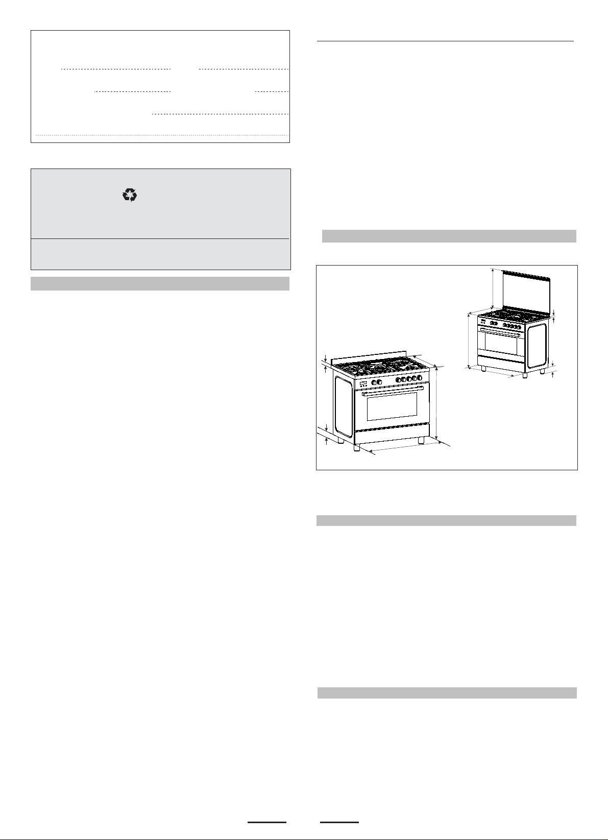
OVERALL DIMENSIONS
570mm
595mm
22mm
40mm
A
mm895
597mm
769 mm
750mm
mm895
A = 95-160 mm
A
INS TALL ATION
The room where the Cooker is installed should have permanent
ventilation as follows:
"Ventilation must be in accordance with AS5601/AG 601 - Gas
Installations. In general, the appliance should have adequate
ventilation for complete combustion of gas, proper flueing and to
maintain temperature of immediate surroundings within safe limits."
Do not install in a bed-sitting room, a bathroom or shower room.
If there is another fuel burning appliance in the same room, a
higher level of ventilation will be required, you should consult
" the safety requirements".
-
In addition to the above, during prolonged use, opening a window
in the same room is recommended. This will avoid the build up
of excessive moisture and condensation.
Important: Fix the chain located next to the gas connection on
both sides of the cooker to the wall to prevent the cooker from
tilting. Both chains must be securely fixed.
Make sure that the wall surface behind the Cooker is noncombustable (will not catch fire).
Where a painted surface is adjacent, a fire retardent paint surface
is recommended. Wallpaper, wood, or fabric should not be used
behind or next to the cooker.
PROVISION FOR VENTILATION
POSITIONING
2
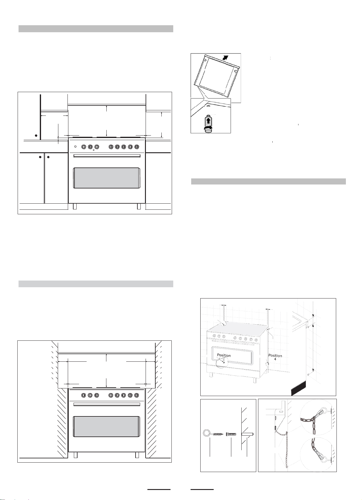
min.100 mm "0" mm "0" mm min "60" mm min "60" mm "0" mm "0" mm
Fig. B
wal
G R Hole
Fig. C
wall
G
Clearances
to
non-
combustible
materials
chain
550 mm 76 mm
a
y
t
o
p
r
a
m
u
d
d
o
YoeIf
a
w
c
p
h
a
h
k
p
e
n
d
c
e
a
n
e
o
g
e
y
Clearances to combustible materials
"Any adjoining wall surface (side or rear) situated within 200mm
of any hob burner must be a suitable non-combustible material
from the edge for a height of 150mm for the entire length
of the cooker.
Any combustible construction above the cooker must be at least
650mm above the maintop." Ensure that a power and gas supply
are nearby. The Cooker should be located carefully so that the
heat produced by it has plenty of space to escape. The diagram
below shows an ideal configuration.
mm
min.10
mm
650
min.
mm
400
min.
Note:
F
itting the adjustable feet ( Fig.1 ).
Fig.1
BPeforehand:
•
Remove
especiall
•
Remove
roceed as f
•
Tilt the ap
the floor.
•
With the
feet into t
the appli
of
•
Repeat t
ou can ma
rder to level
lectricity su
it is necess
djustable fe
hen the oth
ll parts that
the pan su
he accesso
llows:
pliance by r
lates in posi
e mounting
nce.
e process o
e the final a
the applian
ply have be
ary to pull th
t in fully. M
r installatio
are not per
ports and b
ies from the
ising one si
tion, screw t
holes on th
the other s
justments t
e once the
en connecte
e appliance,
ke the final
tasks hav
anently fixe
rners.
oven.
e slightly fr
he adjustabl
underneath
ide.
the feet in
as and
d.
screw the
settings onl
been
,
m
ompleted.
No part of any adjoining wall surface can be made of combustible
materials. The protection of combustible materials
required by Clause 5.12.1.1 of AS5601-2004 is the fixing of 5 mm
thick ceramic tiles to the surface or attaching fire resistant
material to the surface and covering with sheet metal with a minimum
thickness of 0.4 mm.
"If the cooker is being fitted next to cupboards or adjoing wall
surfaces, which are within 200mm from the edge of the hob
burner and of a suitable non-combustible material as specified
in AS5601, then ensure that a distance of at least 6cm is left
between the edge of the cooker and the non-combustible
material. This gap is to allow plenty of space for the heat
produced by the cooker to escape on each side of the cooker.
materials
combustible
non-
mm
650
min.
materials
combustible
non-
WARNING: This appliance is not suitable to be installed on
a base
TO FIX THE COOKER TO THE REAR WALL
WARNING - For safety reasons and to prevent tipping of the appliance,
these stabilizing means must be installed.
The cooker is equipped with 2 chains fixed on each side at the rear of
the cooker near the top (see Fig. A). The chains are fitted with "spring
clips" which must be clipped to the "screw eyes".
Install the "screw eyes" as follows :
1. Drill four 6 mm holes (p osition 1 - 2 - 3 - 4) in the w al l
as in Fig. A.
2. Insert part "R" into the holes then screw in the "screw eyes" part
"G"
see Fig. B.
Note: If the part provided is not suitable for the wall material please
use an appropriate device to ensure secure holding of the "screw
eyes" to the wall.
3. Bring the c ooker near the wall and clip th e cha ins o n the
"screw eyes" as in Fig. C.
IM P OR TANT : If th e c oo ker is mo v e d f or any reas o n
(e.g. maintenance) resulting in the cooker being unclipped from the
wall, the cooker must be re-clipped to the wall at the completion of
the task.
Fig. A
3
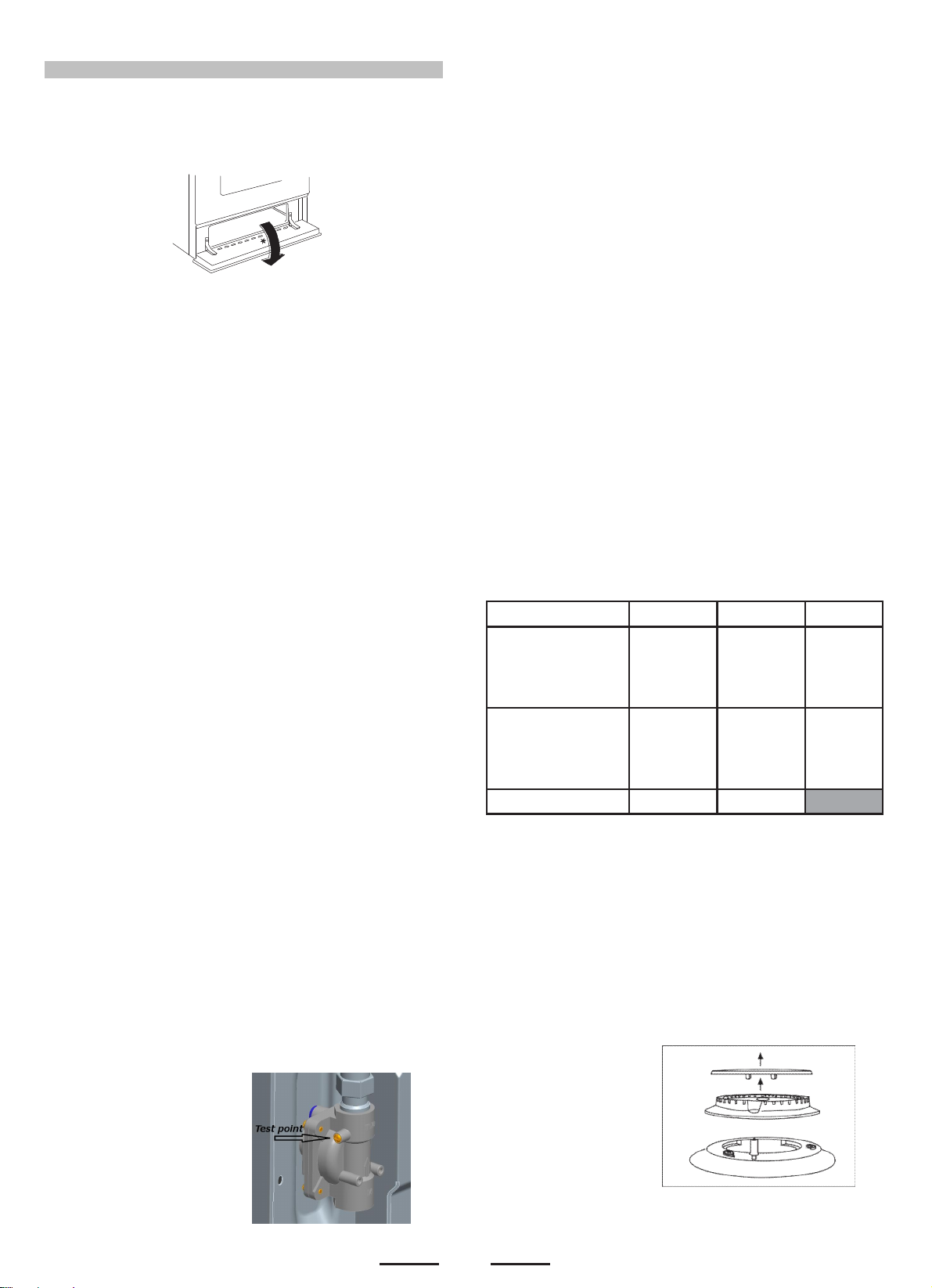
LP Test point
Gas installation must be made in accordance with AS5601;
Also refer to rangehood manufacturers recommendation.
Check gas presure, note the correct setting from the data
plate sealed inside the front appliance drawer *.
Installing the gas cooker :
(Flexible connection are NOT permitted with this
appliance)
- An inlet manifold extension pipe must be fitted to the
appliance. Part supplied in the drawer of the appliance.
- Ensure that the pipe is connetted using the washer
provided and that the braket is screwed to the appliance
as shown in the diagram below.
- Fit the supplied pressure regulator ( for Natural gas )
using the NG test piont adaptor and washer to the inlet
manifold. Ensure the arrow is pointing towards the
appliance and that pressure testpoint is accessible from
the final position.
- Push the cooker back and install the stabilizing chains.
- Connect the appliance inlet manifold to the consumer
piping outlet using only fixed piping. This final connection
is made when the product is pushed back into position by
access under the cooker.
The hose assembly
GAS CONNECTION
- must comply whit ASINZS 1869 Class B or D,
- be of appropriate internal diameter and be kept
as short as possible ( less than 1,2 mm)
- It must not be kinked
- It must not be in contact whit hot surfaces
IT IS RECOMMENDED THAT A SERVICE TAP AND UNION
BE FITTED ADJACENT TO THE APPLIANCE INLET TO
FACILITATE FUTURE SERVICING.
5 burner models: set the burner pressure to 1kPa for Natural Gas
and 2.75kPa for U-LPG with the wok burner operating a full rate'.
For commissioning of the appliance with the regulator for
Natural Gas, the test point pressure should be 1.00kPa with
all burners operating on HIGH.
Apply a manometer to the test nipple and reset the regulator if
necessary. Do not forget to replace the test nipple screw and to
leave the instructions book with the user.
For ULPG a test point fitting must be installed betweeen
the piping and the appliance for the pressureto be
checked to ensure it is operating at 2.75 lPa
Test point for Natural gas
VERY IMPORTANT FOR THE INSTALLER
Do not attempt to turn or stress threaded elbow of the manifold:
you risk damage to this part of the gas appliance which may void
the manufacturers warranty.
Before Leaving - Check all connections for gas leaks with soap
and water. DO NOT use a naked flame for detecting leaks. Ignite
all burners to ensure correct operation of gas valves, burners and
ignition. Turn gas taps to low flame position and observe stability
of the flame.
When satisfied with the cooker, please instruct the user on the
correct method of operation.
In case the appliance fails to operate correctly after all checks
have been carried out, refer to the authorised service provider in
your area.'
GAS CONVERSION AND ADJUSTMENT
When used with natural gas all burners have been preset at our
factory and further adjustment should not be necessary. Conversion
kits to other gases are available from the place of purchase. Do
not attempt to fit the conversion kit yourself. Conversion to U-LPG
gas should only be carried out by an authorized technician.
GAS ADJUSTEMENTS
- change the injectors
- adjust the minimum flow
'When converting from Natural Gas to U-LPG ensure that
the NG regulator is removed and replaced with the Test Point
Assembly. A gas regulator suitable for a supply pressure of 2.75kPa
should be part of the gas tank supply and should be adjusted with
the wok burner operating at maximum.
REPLACEMENT OF THE INJECTORS
When required to operate on other gas replace the injectors in
accordance with information referred to in chart below.
Tab. 1
Gas Type
Natural
U-LPG
Regulator
Adjustments, conversions and gas installations must only be carried
out by an authorised person.
After the replacement of the injectors , replace also the
label of the type of gas
SPECIAL NOTE
After installation or any servicing operation, always ensure that
the appliance is gas sound and that the components are now
operating correctly. Items removed during servicing should be
replaced in the reverse order to their removal.
In order to change the work-top injectors, it is necessary to act as
follows:
- remove the grids
- remove burners
and flame-spreaders.
1.00
kPa Jet mm 0
1.20
0.90
1.50
1.63
2.75
0.73
0.53
0.95
1.00
NG Regulator
Bur ners Power MJ/h
Sem irapid
Aux iliary
Rapid
Triple Crown
Sem irapid
Aux iliary
Rapid
Triple Crown
adaptor
7.1
4.0
11.0
12.7
7.1
3.7
11.7
13.0
4
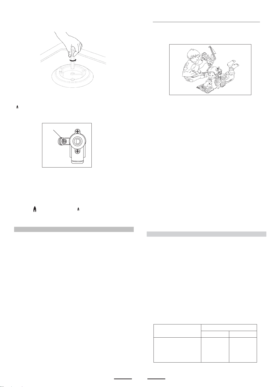
- change the injector (see Fig. D) and replace it with another one
- 1 Minute
Tour -
suitable for the new type of gas (see Tab. 1)
Fig. D
MINIMUM FLOW ADJUSTMENT FOR HOB-TOP TAPS
In order to adjust the minimum flame setting proceed as follows:
switch the burner on, and set the knob at the minimum position
. . Remove the knob from the tap,
The minimum adjusting screw «Z» is on the body of the gas tap
(Fig. 2).
Z
Unscrew the adjusting screw in order to increase the flow or screw
it to decrease the flow.
The correct adjustment is obtained when the flame has a length
of about 3 or 4 mm.
For butane/propane gas, the adjusting screw must be screwed
in thigt.
Make sure that the flame does not go out turning quickly from the
max. flow to the minimum flow .
Refit the knob again.
The appliance must be installed by a suitably qualified person in
accordance with these instructions and with the requirements of
the Australian Wiring Rules AS/NZS 3000.
Fixed wired installations are to be provided with suitable isolation
means in accordance with the said rules.
Any plug socket installed for the purpose of connecting the appliance
to supply must be readily accessible when the appliance is installed.
Before making the connection, make sure that:
1) the safety circuit-breaker and the electrical system are able to
withstand the load of the appliance (see nameplate).
2) the power supply system has an earth connection in good
working order in accordance with the regulations in force;
IMPORTANT
The wires in the mains lead are coloured in accordance with the
following code:
GREEN & YELLOW.........................................................EARTH
BLUE ...........................................................................NEUTRAL
BROWN ...............................................................................LIVE
Electric power ..1,5 mm2 3 core cable (15 amp. Fuse required).
Should conform to local authority requirements.
Also refer to rangehood manufacturers recommendations.
This appliance is supplied with a plug & cord, simply plug into a
3 pin household socket outlet witch is properly earthed.
If the supply cord is damaged, it must be replaced by an autherised
service agent.
WARNING: THIS APPLIANCE MUST BE EARTHED.
The flexible mains lead and plug must not be in contact with hot
surfaces.
Fig. 2
ELECTRICAL CONNECTION
WARNING:
Children should be kept away while the oven or grill is in use
since accessible parts become hot.
- WARNING -
During use, the appliance becomes hot.
Care should be taken to avoid touching heating elements inside
the oven.
- Do not use oven base panel as a shelf, make use of the oven
shelves.
- To avoid splattering and smoke, position collecting tray under
the grill with some water in it.
- Always turn pan handles to the side or to the back of the hob.
If they are left out into the room they can easily be hit or reached
by children, this knocking the pan off the hob.
- Don't let children sit down or play with the oven door. Do not
use the drop down door as a stool to reach above cabinets.
- Once your cooking is over make sure to close the main gas
supply.
WARNING
* This appliance is not intended for use by young children or
infirm persons without supervision.
* Young children should be supervised to ensure that they do
not play with the appliance.
- WARNING -
In order to prevent accidental tipping of the appliance, for example
by a child climbing onto the open oven door, the stabilizing means
must be installed.
2nd SECTION FOR THE USER
Be safe
Please read the rest of the instruction book which contains
important information to help you use the appliance safely and
efficiently.
Gas and Electricity on
Make sure that the gas supply is turned on and that the appliance
is plugged in and switched on. The ignitor needs electricity.
In case there is no electric current, the burner can also be lighted
using a match.
It is recommended that pans suitable to the size of the burner
should be used as follows:
5
BURNERS
AUXILIARY
SEMI-RAPID
RAPID
TRIPLE CROWN
fl min.
B0 mm
120 mm
200 mm
230 mm
PANS
fl max
160 mm
200 mm
230 mm
260 mm
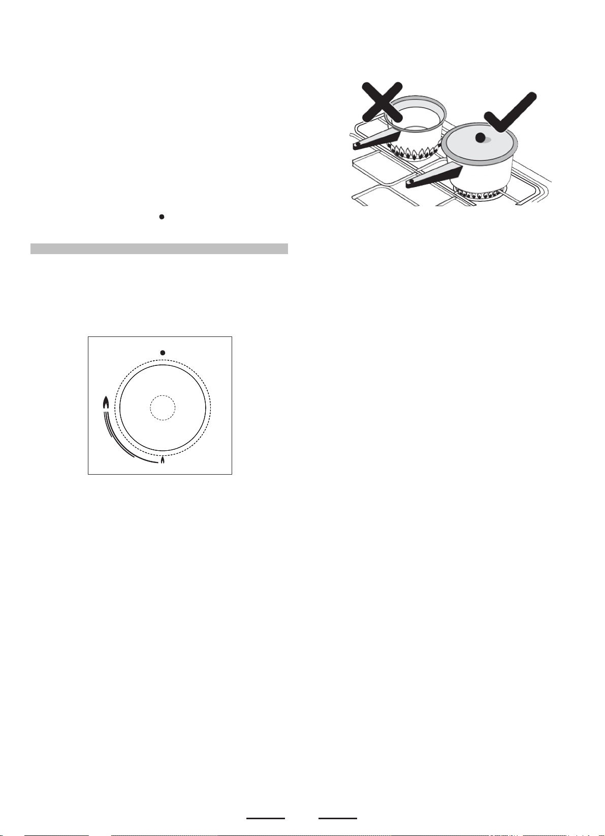
Always use pans with a flat base diameter, which are well balanced
and stable in use, a pan which overhangs the hotplate should not
be used. Avoid using old, misshapen pans, or pans which are
unstable when placed on a flat surface. Do not use "split pans"
as they are inherently unstable.
To save gas, always position pans centrally over the burners and
adjust the flames so that they do not lick up the sides of the pan
and only the base is heated. Always put lids on saucepans and
boil only the amount of liquid you use. When the liquid has boiled
adjust the setting to maintain a simmer. Do not light the burner
until the pan is in position and turn off the burner before removing
the pan. In hard water areas, descale kettles regularly. For safety,
keep saucepan handles turned to a safe position so they are out
of reach of small children and cannot be accidentally knocked.
To tunr the burner OFF, turn the control knob clockwise to the
OFF setting (marked with a dot )
Automatic electric ignition
To turn on a burner, press the knob corresponding to the
selected burner and turn it anticlockwise to the maximum
position. Keeping the knob pressed, the electric automatic
ignition of the burner will be started up. In case there is not
electric current, the burner can also be lighted using a
match.
The small flame indicates the 'low position'.
Turn the knob to it after the contents of a pan have boiled.
The smaller burners are for smaller pans and simmering. Make
sure flames are under the pans. Using a lid will help the contents
boil more quickly.
WARNING
It is not recommended to press push button for ignition if all the
burners are not located in the proper positions. The burner heads,
burner skirts and pan supports are removable for better cleaning:
Always ensure that the burner skirts and heads are replaced
correctly so that the burners function safely and correctly.
During the use of the appliance pay attention that water or any
liquid does not enter into the appliance through the holes of the
burners or around the rods of the valves or the push button
electronic lighter.
Water or juice will produce dangerous short-circuits and can
seriously damage the working of the Hotplate.
6
 Loading...