


 Loading...
P8000
P8000
3/12-Channel ECG Unit
Art.-no.: 9740440041 Rev.: a
User Guide

Sales and Service Information
The ESAOTE sales and service centre network is world-wide. For the address of your local distributor, contact your nearest ESAOTE subsidiary. In case of difficulty a complete list of all distributors and subsidiaries is provided on our internet site: http://www.esaote.com
Distributed by:
ESAOTE S.P.A |
Tel: +39 055 4229 1 |
Via Di Caciolle 15 |
Fax: +39 055 4229 208 |
50127 Firenze, Italia |
web:www.esaote.com |
Manufactured by:
SCHILLER AG |
Phone: +41 (0) 41 766 42 42 |
Altgasse 68 |
Fax: +41 (0) 41 761 08 80, |
CH-6341 Baar, Switzerland |
E-mail: sales@schiller.ch |
Web: |
www.schiller.ch |
Article-No.: 9740440041 Rev.: a Issue date: 23.12.03
Ref.S.: 2.510532

Art.-no.: 9740440041 Rev.: a
User Guide |
|
|
Contents |
|
|
1 |
Safety notes .............................................. |
3 |
1.1 |
Responsibility of the User .................................................. |
3 |
1.2 |
Intended Use ........................................................................ |
3 |
1.3 |
Organisational Measures..................................................... |
3 |
1.4 |
Safety-conscious Operation................................................ |
4 |
1.5 |
Safety Facilities .................................................................... |
4 |
1.6 |
Operation with other Devices.............................................. |
5 |
1.7 |
Maintenance.......................................................................... |
5 |
1.8 |
Safety Symbols and Pictograms......................................... |
6 |
1.9 |
Terms of Warranty................................................................ |
7 |
2 |
Introduction .............................................. |
8 |
2.1 |
Features................................................................................. |
8 |
2.1.1 |
Standard Features ............................................................................. |
8 |
2.1.2 |
Optional Features............................................................................... |
8 |
2.2 |
Operating Philosophy Overview ......................................... |
9 |
2.2.1 |
Initiating Functions or Tasks .............................................................. |
9 |
2.2.2 |
Main Components of the P8000....................................................... |
10 |
2.2.3 |
Back Panel....................................................................................... |
10 |
2.3 |
Keypad................................................................................. |
11 |
2.4 |
LCD Screen ......................................................................... |
13 |
3 |
Operation ................................................ |
14 |
3.1 |
Start-up and Initial Preparation ......................................... |
14 |
3.1.1 |
Connecting P8000............................................................................ |
14 |
3.1.2 |
Battery Operation............................................................................. |
15 |
3.1.3 |
Switching ON and OFF .................................................................... |
15 |
3.1.4 Isolating the Mains Supply ............................................................... |
15 |
|
3.1.5 |
Potential Equalisation....................................................................... |
15 |
3.1.6 |
Inserting Printing Paper ................................................................... |
16 |
3.1.7 |
LCD contrast adjustment.................................................................. |
16 |
3.2 |
Entering Patient Data ......................................................... |
17 |
4 |
Resting ECG ........................................... |
18 |
4.1 |
Electrode Placement .......................................................... |
18 |
4.2 |
Further Lead Combinations............................................... |
20 |
4.2.1 |
Nehb Leads...................................................................................... |
20 |
4.2.2 |
Electrode Positions for Additional Leads.......................................... |
21 |
4.2.3Electrodes and Neutral Electrodes Identification and
|
Colour Code..................................................................................... |
22 |
4.3 |
Skin/Electrode Resistance................................................. |
23 |
4.3.1 High Electrode Resistance Indication .............................................. |
23 |
|
4.3.2 |
Electrode and Patient cable Check (Lead Test)............................... |
23 |
4.4Modes of Operation and Procedural
Overview.............................................................................. |
24 |
4.4.1 Automatic Mode ............................................................................... |
25 |
Page 1

4.4.2 |
Manual Mode ................................................................................... |
26 |
4.4.3 |
Screen (and Manual Printout) Settings ............................................ |
27 |
4.5 |
Memory (option).................................................................. |
29 |
4.5.1 |
Transmitting the Recordings ............................................................ |
30 |
5 |
Setup ........................................................ |
31 |
5.1 |
Entering the SETUP Menu ................................................. |
31 |
5.1.1 |
Navigating in the Setup Screens...................................................... |
31 |
5.2 |
ECG Settings....................................................................... |
32 |
5.2.1 |
Automatic Format 1 and 2 Internal Printer ....................................... |
33 |
5.2.2 |
Automatic Format 1 and 2 External Printer...................................... |
34 |
5.2.3 |
Filters ............................................................................................... |
35 |
5.2.4 Interpretation (Only with version C) ................................................. |
36 |
|
5.2.5 |
Leads ............................................................................................... |
37 |
5.2.6 General (only with version m = Memory) ......................................... |
37 |
|
5.3 |
System Settings.................................................................. |
38 |
5.3.1 |
Unit................................................................................................... |
39 |
5.3.2 |
Communication ............................................................................... |
40 |
5.3.3 |
Test and Information ........................................................................ |
41 |
5.3.3.1 Print Setup ....................................................................................... |
42 |
|
5.3.3.2 Communications Test ...................................................................... |
43 |
|
5.3.3.3 Installing New Software Options (Upgrade)..................................... |
43 |
|
5.3.3.4 Update the Software ........................................................................ |
43 |
|
5.3.3.5 Default Settings................................................................................ |
44 |
|
6 |
Care & Maintenance ............................... |
45 |
6.1 |
Communication (RS-232) Test........................................... |
45 |
6.2 |
12 Monthly Check ............................................................... |
45 |
6.3 |
Maintenance interval for the battery ................................. |
46 |
6.3.1 |
Charging the battery ....................................................................... |
46 |
6.3.2 |
Battery disposal ............................................................................... |
46 |
6.4 |
Changing the fuse and mains voltage .............................. |
47 |
6.5 |
Cleaning............................................................................... |
48 |
6.5.1 |
Cleaning the Casing......................................................................... |
48 |
6.5.2 Cleaning the Patient Cable .............................................................. |
48 |
|
6.5.3 Cleaning the Thermal Print Head..................................................... |
48 |
|
6.6 |
Replacing the Recording Paper ........................................ |
49 |
6.6.1 |
Thermal Paper Handling .................................................................. |
49 |
6.7 |
Fault-Finding ....................................................................... |
50 |
6.7.1 |
Accessories and Disposables .......................................................... |
51 |
7 |
Technical Data ........................................ |
52 |
7.1 |
System ................................................................................. |
52 |
7.2 |
Technical Data for ECG...................................................... |
53 |
7.3 |
Safety Standards ................................................................ |
54 |
8 |
Index ........................................................ |
55 |
Art.-no.: 9740440041 Rev.: a
Page 2

Art.-no.: 9740440041 Rev.: a
User Guide |
Safety notes |
1 |
Responsibility of the User |
1.1 |
|
|
|
|
1Safety notes
1.1Responsibility of the User
VThis device must only be used by qualified doctors or trained medical personnel.
VThe numerical and graphical results and any interpretation given must be examined with respect to the overall clinical condition of the patient and the general recorded data quality.
VThe indications given by this equipment are not a substitute for regular checking of vital functions.
VSpecify the competencies of the personnel for operation and repair.
VEnsure that personnel have read and understood these operating instructions. In particular this chapter “safety notes" must be read and understood.
VHave damaged or missing components replaced immediately.
VThe operator is responsible for compliance with all applicable accident prevention regulations and safety regulations.
1.2Intended Use
VThe P8000 is a 3/12-channel, ECG device used for the recording, analysis and evaluation of ECG Recordings. Recordings made with the P8000 can be used as a diagnostic aid for heart function and heart conditions. The P8000 is designed for indoor use and can be used for all patients of both sexes, all races, and all ages.
VThere is no danger for patients with pacemaker.
VOnly operate the device in accordance with the specified technical data.
VThe system is not designed for sterile use nor is it designed for outdoor use.
VDo not use this unit in areas where there is any danger of explosion or in the presence of flammable gases such as anaesthetic agents.
V


 This unit is CF classified and defibrillation protected only when the original patient cable is used. However, as a safety precaution when possible, remove electrodes before defibrillation.
VThis product is not designed for internal use.This product is not designed for direct cardiac application.
1.3Organisational Measures
VBefore using the unit, ensure that an introduction regarding the unit functions and the safety precautions has been provided by a medical product representative.
VKeep these operating instructions in an accessible place for reference when required. Make sure that they are always complete and legible.
VObserve the operating instructions and maintenance instructions.
VThese operating instructions do not override any statutory or local regulations, or procedures for the prevention of accidents and environmental protection.
Page 3

1 Safety notes
1.4Safety-conscious Operation
1.4Safety-conscious Operation
V Make sure that the staff has read and understood the operating instructions - particularly the "Safety Notes" chapter.
V Do not touch the unit casing during defibrillation.
VIt must be ensured that neither the patient nor the electrodes (including the neutral electrode) come into contact with other conducting objects (even if these are earthed).
VImmediately report any changes that impair safety (including operating behaviour) to the person responsible.
VDo not place any liquids on the unit. If liquid should be spilled over the device, immediately disconnect the device from the mains and wipe it. The device must be serviced before reusing.
1.5Safety Facilities
V Operating the device without the correctly rated fuse, or with defective cables, constitutes a danger to life. Therefore:
– Do not operate the unit if the earth connection is suspect or if the mains lead is damaged or suspected of being damaged.
–Damaged cable connections and connectors must be replaced immediately.
–The electrical safety devices, such as fuses, must not be altered.
–Ruptured fuses must only be replaced with the same type and rating as the original.
Art.-no.: 9740440041 Rev.: a
Page 4

User Guide |
Safety notes |
1 |
Operation with other Devices |
1.6 |
|
|
|
|
1.6Operation with other Devices
V Use only accessories and other parts recommended or supplied by ESAOTE. Use of other than recommended or supplied parts may result in injury, inaccurate information and/or damage to the unit.
VAncillary equipment connected to the analogue and/or digital interfaces must be certified according to the respective IEC standards (e.g. IEC/EN 60950 for data processing equipment and IEC/EN 60601-1 for medical equipment). Furthermore all configurations shall comply with the valid version of the system standard IEC/ EN 60601-1-1. Everybody who connects additional equipment to the signal input part or signal output part configures a medical system, and is therefore responsible that the system complies with the requirements of the valid version of the system standard IEC/EN 60601-1-1. If in doubt, consult the technical service department or your local representative.
–EC/EN 60601-1-1 states that the patient must remain at least 1.5 meters clear of the unit. If this is not possible, a safety isolating transformer must be installed.
VAny other equipment used with the patient must use the same common earth as the P8000.
VPrecautions must be observed when using high frequency devices. Use the special high frequency ESAOTE patient cable to avoid possible signal interference during ECG acquisition.
VThere is no danger when using the ECG unit simultaneously with electrical stimulation equipment. However, the stimulation units should only be used at a sufficient distance from the electrodes. If in doubt, the patient should be disconnected from the monitor.
VIf the patient cable should become defective after defibrillation, an electrode becomes displaced, or an electrode resistance is too high, a lead-off indication is displayed in the upper right part of the screen and an acoustic alarm given.
1.7Maintenance
V Danger of electric shock! Do not open the device.No serviceable parts inside. Refer servicing to qualified personnel only.
V Before cleaning and to isolate the mains power supply, switch the unit off and disconnect it from the mains by removing the plug.
VDo not use high temperature sterilisation processes
(such as autoclaving). Do not use E-beam or gamma radiation sterilisation.
VDo not use solvent or abrasive cleaners on either the unit or cable assemblies.
VDo not, under any circumstances, immerse the unit or cable assemblies in liquid.
Art.-no.: 9740440041 Rev.: a
Page 5

1 Safety notes
1.8Safety Symbols and Pictograms
1.8Safety Symbols and Pictograms
The safety level is classified according ANSI Z535.4. The following overview shows the used safety symbols and pictograms used in this manual.
For a direct danger which could lead to severe personal injury or to death.
For a possibly dangerous situation, which could lead to heavy bodily injury or to death.
For a possibly dangerous situation which could lead to personal injury. This symbol is also used to indicate possible damage to property.
For general safety notes as listed in this chapter.
Used for electrical dangers, warnings and other notes in regarding operation with electricity.
Note For possibly dangerous situations, which could lead to damages to property or system failure.
Important or helpful user information
Reference to other guidelines
Potential equalization
CF symbol. This unit is classified safe for internal and external use. However, It is only defibrillation protected when used with the original ESAOTE patient cable!
The unit/component can be recycled.
Notified body of the CE certification (TÜV P.S.)
Art.-no.: 9740440041 Rev.: a
Page 6

User Guide |
Safety notes |
1 |
Terms of Warranty |
1.9 |
|
|
|
|
1.9Terms of Warranty
The ESAOTE P8000 is warranted against defects in material and manufacture for the duration of one year (as from date of purchase). Excluded from this guarantee is damage caused by an accident or as a result of improper handling. The warranty entitles free replacement of the defective part. Any liability for subsequent damage is excluded. The warranty is void if unauthorized or unqualified persons attempt to make repairs.
In case of a defect, send the apparatus to your dealer or directly to the manufacturer. The manufacturer can only be held responsible for the safety, reliability, and performance of the apparatus if:
•assembly operations, extensions, readjustments, modifications, or repairs are carried out by persons authorized by him, and
•the ESAOTE P8000 and approved attached equipment is used in accordance with the manufacturers instructions.
There are no Express or implied warranties which extend beyond the warranties hereinabove set forth. ESAOTE makes no warranty of merchantability or fitness for a particulare purpose with respect to the product or parts therefof.
This equipment has been tested and found to comply with the limits for a class A digital device, pursuant to both Part 15 of the FCC (Federal Communications Commission) Rules and the radio interference regulations of the Canadian Department of Communications. These limits are designed to provide reasonable protection against harmful interference when the equipment is operated in a commercial environment. This equipment generates, uses and can radiate radio frequency energy and, if not installed and used in accordance with this instruction manual, may cause harmful interference to radio communications. Operation of this equipment in a residential area is likely to cause harmful interference in which case the user will be required to correct the interference at his own expense.
Art.-no.: 9740440041 Rev.: a
Page 7

2 Introduction
2.1Features
2Introduction
2.1Features
The ESAOTE P8000 is a 3/12-channel ECG unit designed to record, display, and analyse resting ECGs. The unit has been extensively researched to give an ergonomic, clear interface that‘s easy to use without compromising functionality. The P8000 has the following features:
2.1.1Standard Features
•Alphanumeric keypad and dedicated soft key interface for easy, user friendly operation.
•Integral thermal quality printer with various user defined print format options.
•Measurements and average cycles with automatic and manual printout of the recording.
2.1.2Optional Features
•External printer
•ECG Interpretation
•Memory for up to 40 recordings
•Thrombolysis
Art.-no.: 9740440041 Rev.: a
Page 8
Art.-no.: 9740440041 Rev.: a
User Guide |
Introduction |
2 |
Operating Philosophy Overview |
2.2 |
|
|
|
|
2.2Operating Philosophy Overview
There are broadly four types of data display as follows:
Data Acquisition and ECG |
In this screen the real-time ECG is displayed. From this screen a continuous printout |
Recording Screen |
can be initiated and/or an auto recording can be made. In auto mode 10 seconds of |
|
ECG data is analysed and averaged and the results given on a printout. The format |
|
and data of an auto mode printout is independent of the screen display and is defined |
|
in the setup screens. (See paragraph 5.2 page 32). |
|
An auto mode recording can also be stored in the memory for later print or |
|
transmission. |
Memory Screen |
In this screen stored recordings can be accessed, printed and transmitted. |
Patient Data Screen |
Patient data entry via the keypad. |
Data Entry and Setup |
In these screens all system settings are made. |
2.2.1Initiating Functions or Tasks
Most functions and tasks are initiated by the 5 softkeys (1) situated immediately below the LCD. The function of the softkeys varies according to the screen displayed and is displayed on the LCD immediately above the key itself.
During data acquisition, further dedicated function keys are provided to make an auto mode recording (START) and to stop a manual printout (STOP). The top line of the alphanumeric keypad, additionally enables direct settings of lead group, trace speed and sensitivity, filter on/off and other functions, for both the real-time display and (manual) printout.
LEAD |
MANUAL |
MENU |
|
TEST |
|||
|
|||
1 |
|
|
Fig. 2.1 Start-up screen
Page 9
2 Introduction
2.2Operating Philosophy Overview
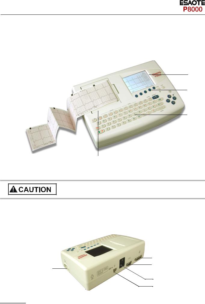
2.2.2Main Components of the P8000
(1)LCD Display
(2)Softkey control
(3)Keypad and dedicated function keys
(4)Printer
1
2
3
4
2.2.3Back Panel
V All externally connected hardware must be approved by ESAOTE. Connection of any hardware not approved by ESAOTE is at the owner‘s risk. The unit warranty may also be invalid. See also safety note paragraph 1.6.
(1)Patient cable connector
(2)LPT connector for the connection of an external printer
(3)RS-232 for connection of a modem or a PC for export of stored recordings
(4)Mains connector (with fuse above)
(5)Potential equalisation stud
2
3
1
4
5
Art.-no.: 9740440041 Rev.: a
Page 10

|
User Guide |
|
|
Introduction |
2 |
|
|
|
Keypad |
2.3 |
|
2.3 |
Keypad |
|
|
|
|
|
LEAD |
MANUAL |
MENU |
|
|
|
TEST |
|
|
||
|
|
|
|
||
|
|
|
2 |
3 |
|
|
|
|
|
|
|
|
1 |
|
|
|
|
(1) Softkeys - the function of these keys changes depending on the screen displayed. The function of these keys is shown on the screen above the keys. If nothing is written above a softkey, it has no function for the current screen.
(2)Auto Mode recording (in Auto mode 1). Press the SHIFT followed by the START key (2) for auto mode 2.
(3) STOP printout
Art.-no.: 9740440041 Rev.: a
Page 11

2 Introduction
2.3Keypad
4 |
5 |
6 |
7 |
8 |
9 |
10 |
11 |
|
|
12 |
13 |
|||||||||||
|
|
|
|
|
|
|
|
|
|
|
|
|
|
|
|
|
|
|
|
|
|
|
|
|
|
|
|
|
|
|
|
|
|
|
|
|
|
|
|
|
|
|
|
|
|
|
|
|
|
|
|
|
|
|
|
|
|
|
|
|
|
|
|
|
|
|
|
|
|
|
|
|
|
|
|
|
|
|
|
|
|
|
|
|
|
|
|
|
|
|
|
|
|
|
|
|
|
|
|
|
|
|
|
|
|
|
|
|
|
|
|
|
|
|
|
|
|
|
|
|
|
|
|
|
|
|
|
|
|
|
|
|
|
|
|
|
|
|
|
|
|
|
|
|
|
|
|
|
|
|
|
|
|
|
|
|
|
|
|
|
|
|
|
|
|
|
|
|
|
|
|
|
|
|
|
|
|
|
|
|
|
|
|
|
|
|
|
|
|
|
|
|
|
|
|
|
|
|
|
|
|
|
|
|
|
|
17 |
16 |
15 |
14 |
(4)The top figures on the number keys ‘1‘and ‘2‘(designated < and >), change the lead group displayed on the screen, forward and backward resp.
(5)Auto sensitivity key - automatically sets the ECG printout sensitivity (in AUTO mode only) to the best setting for the signal strength (5mm/mV or 10mm/mV)
(6)The top figures on the number keys designated 5, 10, and 20 set the sensitivity of the ECG both on the screen and on the (manual) printout. The sensitivity is 5, 10 or 20 mm / mV.
(7)The top figures on the number keys designated 5/10, 25, and 50 set the speed of the ECG both on the screen and on the (manual) printout. The speed on the screen can only be set to 25 or 50 mm/s. The speed of the manual printout can be 5, 10, 25 or 50 mm/s. The 5 and 10 mm/s settings are both on the same key which toggles the two speeds.
(8)Inserts a 1mV reference marker on the screen and printout. Recentres the trace.
(9)Toggles the QRS beeper ON/ OFF
(10)Myogram filter ON / OFF. The cutoff frequency can be user defined in ‘Setup‘.
(11)Patient data key. Press this key to enter a new patient or modify the data for the current one.
(12)Delete last typed character.
The patient data screen, or the ECG screen is the first screen displayed on initial switch on. This is set for user preference in the SYSTEM SETTINGS/UNIT (see page 39).
(13)ON / OFF Key
(14)Mains Indicator - lit when mains connected.
(15)Press the function key (16) and the UP/DOWN arrows to adjust screen contrast.
When entering patient data use the LEFT/RIGHT arrow keys to move the cursor in the data field. Use the UP/DOWN arrow keys to go up/down to the next data entry
(16)Shift key to select capital letters.
(17)Function Key. When pressed before another key, initiates the second function of that key.
For example, second letters on the keypad -, é, è, ç, Ø, ›, @ etc., are entered by holding the function key before pressing the letter key.
Art.-no.: 9740440041 Rev.: a
Page 12

Art.-no.: 9740440041 Rev.: a
User Guide |
Introduction |
2 |
LCD Screen |
2.4 |
|
|
|
|
2.4LCD Screen
The display will vary according to the current task being carried out. In all screens however, the top and bottom lines always display the same information: the top line displays system information, and the bottom line always gives the softkey options.
The following is an example of a typical resting ECG screen.
1 |
~ |
|
4 |
5
2 |
6 |
7
8
9
10
3 |
LEAD |
MANUAL |
MENU |
|
TEST |
||||
|
Items 1, 2 and 3 are in the same position for all screens.
(1)Top line - time, date, patient name, and current power source - mains (~), or battery ( 
 ). When battery capacity is limited the battery symbol flashes.
(2)Data acquisition area or data entry area.
(3)Softkey designation. Pressing the key below the text carries out the function indicated. The options available will change according to the screen displayed.
Items 4 to 10 are specific for ECG acquisition only:
(4)Current Heart Rate (averaged over 4 beats and refreshed every 2 seconds). The HR is also given on a manual printout. Note that with an auto mode printout the HR is averaged over the full 10 seconds of the recording.
(5)Electrode connections - when an electrode indication flashes (an audible alarm is also given), it indicates that the electrode resistance is too high. The electrode(s) must be reapplied.
(6)Sensitivity 5, 10 or 20 mm/mV. Change the sensitivity with the keys 3 (auto), 4, 5 and 6. An ‘A‘ in this box indicates that automatic sensitivity is selected (auto mode printout only).
(7)Speed 25 or 50 mm/s. Change the speed with the keys 8 and 9.
(8)Lead indication (leads currently displayed on the screen). Change the lead group with the < and > keys on the keypad.
(9)1Myogram Filter indication - ‘Filter ON’ or ‘Filter OFF’. The filter is applied with the filter key.
(10)Area for system messages or instructions.
1.The frequency of the filter cutoff is defined on page 35 menu Filters.
Page 13

3 Operation
3.1Start-up and Initial Preparation
3Operation
3.1Start-up and Initial Preparation
V Danger of electrical shock. Do not operate the unit if the earth connection is suspect or if the mains lead is damaged or suspected of being
damaged.
3.1.1Connecting P8000
(1)Potential equalisation
(2)Mains connection (115 or 230 V)
(3)RS-232 (see safety note paragraph 1.6)
(4)Printer (see safety note paragraph 1.6)
5
6
7
Fig. 3.1 P8000 back panel
1.Check Voltage setting (2) 115 or 230 V. Refer to chapter 6.4 for the mains voltage.
2.Connect the power cable at the rear of the unit. The mains indicator lamp (6) is always lit when the unit is connected to the mains supply. If the unit is switched on, the relevant symbol is displayed on the LCD (7). Leave the P8000 connected to the mains for 7 hours to fully charge the battery.
3.Connect the potential equalisation cable and all other necessary cables at the rear of the P8000.
4.Press the on/off button (5). The patient data or the ECG acquisition screen is displayed (see paragraph 5.3.1).
5.Check the settings according to chapters 5.
6.Connect the patient cable on the right side panel.
Art.-no.: 9740440041 Rev.: a
Page 14

User Guide |
Operation |
3 |
Start-up and Initial Preparation |
3.1 |
|
|
|
|
3.1.2Battery Operation
Important
The unit can either be operated from the mains supply or from the built-in rechargeable battery. The power source is indicated on the top line of the LCD. The internal bat-
tery provides power for up to 3 hours.
1
• When the unit is running on battery power a battery symbol (1) is displayed.
• When working from battery power, the unit is automatically switched off after 5 minutes (30 seconds if battery capacity is limited) if no key is pressed.
• for Battery recharging refer to chapter 6.3.
• The unit can remain connected to the mains supply without damage to either the battery or the unit.
3.1.3Switching ON and OFF
«The P8000 is switched ON and OFF with the ON/OFF key.
3.1.4Isolating the Mains Supply
To isolate the power supply, remove the mains plug from the wall socket. (see Fig. 3.1)
3.1.5Potential Equalisation
The potential equalisation stud (see Fig. Fig. 3.1) at the rear of the unit can be used to equalise the ground potential of the P8000 to that of all mains powered equipment in the vicinity. Use the hospital or building common ground
VTo prevent the possibility of leakage current when an external printer is con-
nected, always ensure that the mains lead, or the potential equalisation is attached to the P8000
Art.-no.: 9740440041 Rev.: a
Page 15

3 Operation
3.1Start-up and Initial Preparation
3.1.6Inserting Printing Paper
Important
The device is delivered without printing paper installed. Only use original ESAOTE printing paper. The thermo-paper is sensitive to heat, humidity and chemical vapours. Store the paper in a cool and dry area.
1.Press the locking catch (1) to the right.
2.Open the printer door upward.
1
3.Insert paper and pull it down.
4.Close the cover. Be sure that the paper lies exactly between the rails.
5.Press the STOP key to transport the paper to the start position.
3.1.7LCD contrast adjustment
« Press the function key FN and the UP/DOWN arrows to adjust screen contrast.
Art.-no.: 9740440041 Rev.: a
Page 16
Loading...