

Page 1

Home > SPR1100 Handbook
1553-FGC 101 1400 Uen A
Ericsson SPR1100
Stream Processor
HANDBOOK
SPR11/CHASSIS/1AC, SPR11/CHASSIS/2AC, SPR11/CHASSIS/1DC,
SPR11/CHASSIS/2DC and Options
Software Version 6.0.11 (and later)
© Ericsson AB 2011. All rights reserved
Page 2

Home > SPR1100 Handbook > Preliminary Information
Preliminary Information
Scope of This Information
This topic defines who should use this information, and what equipment and options are
covered.
About This Information
Tabulates the history of this information. Lists the templates and style sheets used to create
the file.
Trademarks
List the trademarks and registered trademarks associated with the equipment.
Warning, Cautions and Notes
Defines the use and format of Warnings, Cautions and Notes throughout this information.
Contact Information
Gives contact information for Ericsson Customer Services, and Technical Training.
Compliance Statements
Compliance statements relating to EN55022/AS/NZS 3548 and FCC.
© Ericsson AB 2011. All rights reserved
Page 3
Home > SPR1100 Handbook > Preliminary Information > Scope of This Information
Scope of This Information
Who Should Use this Handbook
This guide is written for operators and users of the Ericsson SPR1100 and describes its
functions and operation. It will assist in the installation and day-to-day care and operation of
the unit. Maintenance information that requires covers to be removed is not included.
WARNING!
Do not remove the covers of this equipment. Hazardous voltages are present within this
equipment and may be exposed if the covers are removed. Only suitably trained and
experienced service engineers are permitted to service this equipment.
CAUTION!
Unauthorised maintenance or the use of non-approved replacements may affect the
equipment specification and invalidate any warranties.
Equipment Covered by this Handbook
Equipment Models
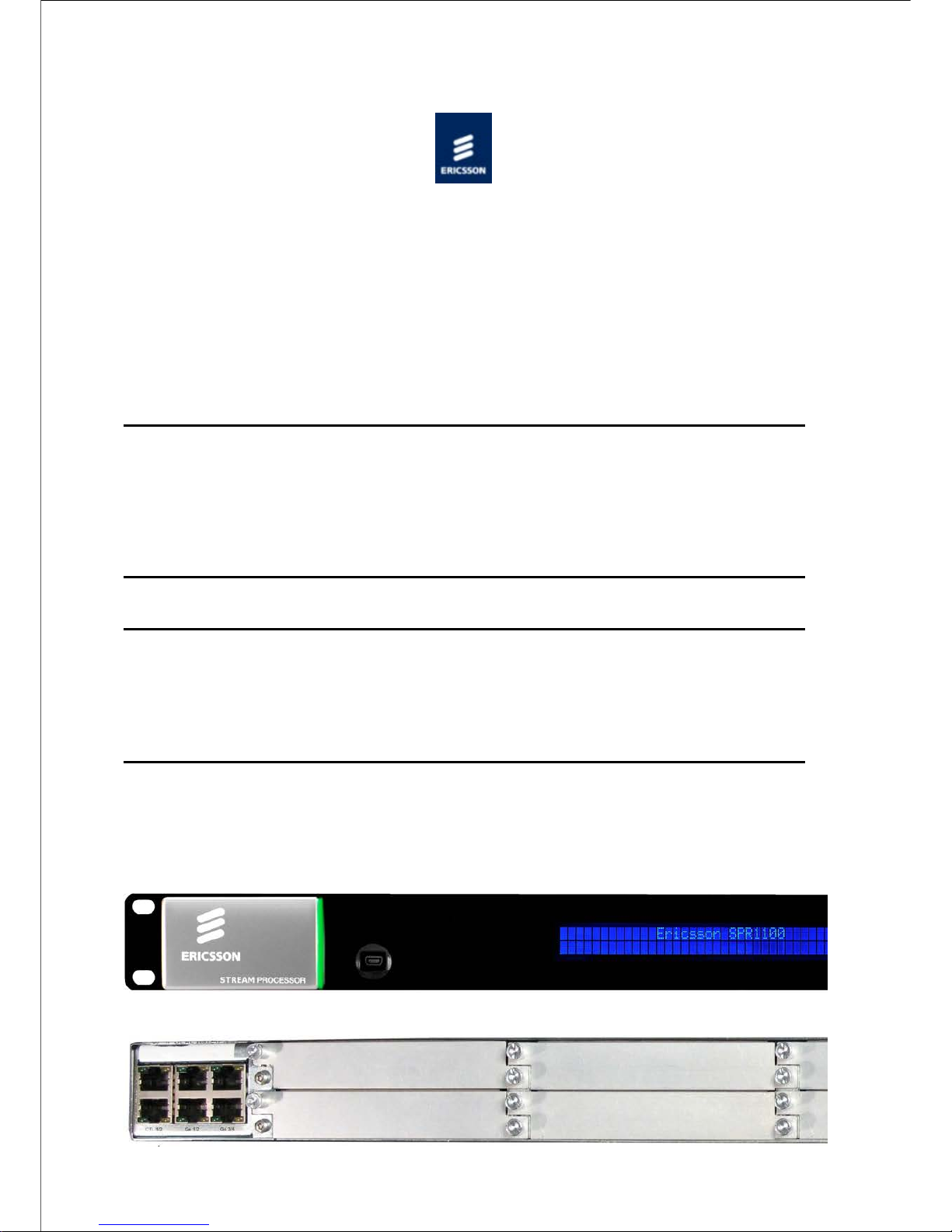
Front View of the Ericsson SPR1100.
Page 4
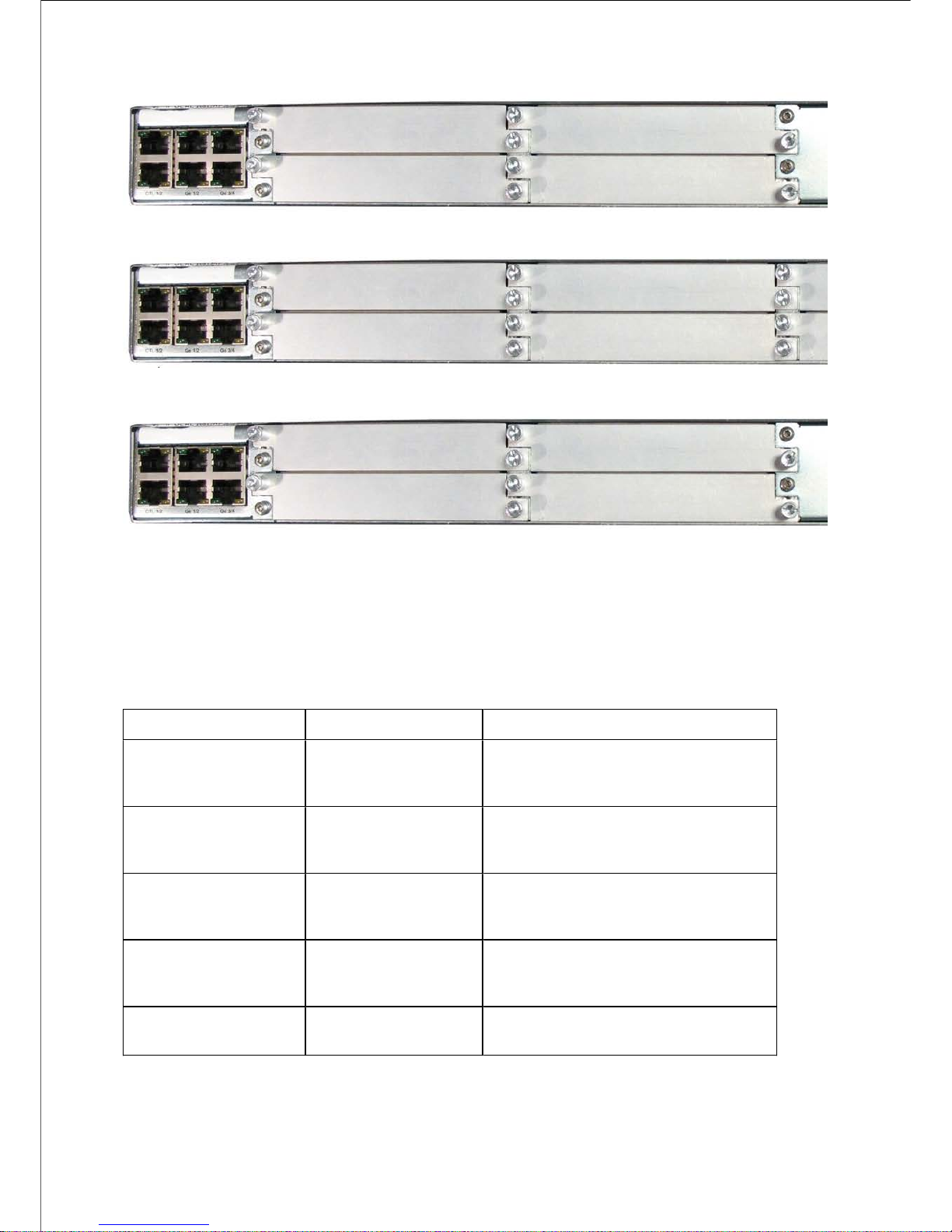
Rear View of the Ericsson SPR1100, single AC PSU variant.
Rear View of the Ericsson SPR1100, dual AC PSU variant
Rear View of the Ericsson SPR1100, single DC PSU variant.
Rear View of the Ericsson SPR1100, dual DC PSU variant.
Product Codes
This information covers products with the marketing codes shown in the following table
Marketing Code
Description
Summary of Features
SPR11/CHASSIS/1AC
Ericsson SPR1100
Chassis with single
AC input
See Introduction>Base
Chassis>Base Unit (AC)
SPR11/CHASSIS/2AC
Ericsson SPR1100
Chassis with dual AC
input
See Introduction>Base
Chassis>Base Unit (Dual AC)
SPR11/CHASSIS/1DC
Ericsson SPR1100
Chassis with single
DC input
See Introduction>Base
Chassis>Base Unit (DC)
SPR11/CHASSIS/2DC
Ericsson SPR1100
Chassis with dual DC
input
See Introduction>Base
Chassis>Base Unit (Dual DC)
SPR/HWO/MPM1
MPM1 HD/SD
Transcoder Module
See Introduction>Transcoder
Cards>MPM1 Transcoder
Firmware/Software Versions
This information covers the functionality of the firmware/software versions which are
Page 5

contained within the Software Release Version 6.x.x .
This handbook continues to be relevant to subsequent build versions where the functionality
of the equipment has not changed. Where the build standard changes the functionality, a
new issue of this handbook will be provided.
© Ericsson AB 2011. All rights reserved
Page 6

Home > SPR1100 Handbook > Preliminary Information > About this Information
About this Information
Revisions
Any revision of this information will be by a complete reissue.
Issues are listed below:
Issue
Date
Build
Version
Comments
A
September
2011
6.0.11
Initial
release.
© Ericsson AB 2011. All rights reserved
Page 7

Home > SPR1100 Handbook > Preliminary Information > Trademarks
Trademarks
General
All best endeavours have been made to acknowledge registered trademarks and
trademarks. Any notified omissions will be rectified in the next issue. Some trademarks may
be registered in some countries but not in others.
Registered trademarks and trademarks used are acknowledged below and marked with their
respective symbols. However, they are not marked further within the text.
Copyright
© Ericsson AB 2011. All rights reserved. No part of this document may be reproduced in any
form without the written permission of the copyright owner.
Disclaimer
The contents of this document are subject to revision without notice due to continued
progress in methodology, design and manufacturing. Ericsson AB shall have no liability for
any error or damage of any kind resulting from the use of this document.
Registered Trademarks
Dolby® is a registered trademark of Dolby Laboratories Licensing Corporation.
DTS® is a registered trademark of Digital Theater Systems, Inc
Ethernet® is a registered trademark of Xerox Corporation.
Trademarks
Ethafoam™ is a trademark of The Dow Chemical Company.
Pozidriv™ is a trademark of European Industrial Services.
Reflex™ is a trademark of Ericsson AB.
Stratocell™ is a trademark of the Sealed Air Corporation.
© Ericsson AB 2011. All rights reserved
Page 8

Home > SPR1100 Handbook > Preliminary Information > Warnings, Cautions and Notes
Warnings, Cautions and Notes
Heed Warnings
All warnings on the product and in the operating instructions should be adhered to. The
manufacturer can not be held responsible for injuries or damage where warnings and
cautions have been ignored or taken lightly.
Read Instructions
All the safety and operating instructions should be read before this product is operated.
Follow Instructions
All operating and use instructions should be followed.
Retain Instructions
The safety and operating instructions should be retained for future reference.
WARNING!
Warnings give information which, if strictly observed, will prevent personal injury or death,
or damage to personal property or the environment. They are boxed for emphasis, as in this
example, and are placed immediately preceding the point at which the reader requires
them.
CAUTION!
Cautions give information which, if strictly followed, will prevent damage to equipment or
other goods. They are boxed for emphasis, as in this example, and are placed immediately
preceding the point at which the reader requires them.
Page 9

NOTE:
Notes provide supplementary information. They are highlighted for emphasis,
as in this example, and are placed immediately after the relevant text.
© Ericsson AB 2011. All rights reserved
Page 10

Home > SPR1100 Handbook > Preliminary Information > Contact Information
Contact Information
Ericsson Customer Services
Support Services
Our primary objective is to provide first class customer care that is tailored to your specific
business and operational requirements. All levels are supported by one or more service
performance reviews to ensure the perfect partnership between Ericsson and your business.
Warranty
All Ericsson Products and Systems are designed and built to the highest standards and are
covered under a comprehensive 12 month warranty.
Levels of Continuing Ericsson Service Support
For stand-alone equipment, then Ericsson's BASIC Essential support is the value for
money choice for you.
BASIC provides you with year-by-year Service long after the warranty has expired.
For systems support you can choose either Gold Business Critical support or Silver
Business Advantage. These packages are designed to save you costs and protect your
income through enlisting the help of our support specialists.
Call Ericsson Sales for more details.
Where to Find Us
Page 11

Customer Services
Europe, Middle
East and Africa
Tel:
+44 (0) 23 8048 4455
Fax:
+44 (0) 23 8048 4467
Email:
tvsupportemea@ericsson.com
Americas
Tel:
+888 671 1268
US and Canada
Tel:
+678 812 6255
International
Fax:
+678 812 6262
Email:
tvsupportamericas@ericsson.com
Compression
Email:
tvsupport@ericsson.com
Software
Support Centre
China
Tel:
+86 10 8476 8676
Beijing
Fax:
+86 10 8476 7741
Beijing
Tel:
+852 2590 2388
Hong Kong
Fax:
+852 2590 9550
Hong Kong
Email:
tvsupportapac@ericsson.com
Australia and
New Zealand
Tel:
+612 (0) 9111 4027
Fax:
+612 (0) 9111 4949
Email:
tvsupportanz@ericsson.com
Internet
Address
www.ericsson.com
Technical Training
Training Courses
Ericsson provides a wide range of training courses on the operation and maintenance of our
products and on their supporting technologies. We can provide both regularly scheduled
courses and training tailored to individual needs. Courses can be run either at your premises
or at one of our dedicated training facilities.
Where to Find Us
For further information on the Ericsson training programme please contact us:
Page 12

International
Tel:
+44 (0) 23 8048 4229
Fax:
+44 (0) 23 8048 4161
Email:
tvglobaltraining@ericsson.com
Return of Equipment
Contact your regional Ericsson office who will issue directions on how and where to return a
unit for service/repair/upgrade.
© Ericsson AB 2011. All rights reserved
Page 13

Home > SPR1100 Handbook > Preliminary Information > Compliance Statements
EN55022 and CISPR22
This is a Class A product. In a domestic environment this product may cause radio
interference in which case the user may be required to take adequate measures.
FCC
This equipment has been tested and found to comply with the limits for a Class A digital
device, pursuant to Part 15 of the FCC Rules. These limits are designed to provide
reasonable protection against harmful interference when the equipment is operated in a
commercial environment.
This equipment generates, uses and can radiate radio frequency energy and, if not installed
and used in accordance with the Handbook, may cause harmful interference to radio
communications. Operation of this equipment in a residential area is likely to cause harmful
interference in which case the user will be required to correct the interference at ones own
expense.
FCC Code of Federal Regulations (CFR) Title 47 – Telecommunications, Part 15: radio
frequency devices, subpart B – Unintentional Radiators.
© Ericsson AB 2011. All rights reserved
Page 14

Home > SPR1100 Handbook > Read This First
Read This First!
Personnel
Ensure the personnel designated to fit the unit have the appropriate skills and knowledge. If
in any doubt, contact Customer Services (see Contact Information).
Installation
Installation of the product should follow these instructions, and should only use installation
accessories recommended by the manufacturers. When rack mounted, this equipment must
have shelf supports as well as being fixed at the front panel.
Mechanical Support
Do not use this product as a support for any other equipment.
Web Browser access
This product is designed to support control through Web browser access. The only
supported browser is Microsoft IE8 (earlier versions of IE are not supported)
© Ericsson AB 2011. All rights reserved
Page 15

Home > SPR1100 Handbook > Introduction
Introduction
The Unit is a flexible platform consisting of a base unit or chassis into which between one
and six Media Processing Modules (MPMs) can be plugged. The base unit provides an
Ethernet control interface, and Ethernet data interfaces, it also provides transport stream
processing functionality. Other functionality such as video / audio transcoding, or other
input or output interfaces are provided by the media processing modules.
License Keys
License Keys control the availability of some of the features accessible from the unit and are
issued to a specific chassis, not a module, and are held within the chassis.
Base Chassis
This section introduces the chassis and describes the functions associated with the host
controller.
Media Processing Module (MPM)
The following media processing module is available:
MPM1 HD/SD Transcoder
This provides high quality MPEG-2 and H.264 Video transcoding, and multi-standard
audio transcoding.
© Ericsson AB 2011. All rights reserved
Page 16

Home > SPR1100 Handbook > Introduction > License Keys
License Keys
Overview
License Keys control the availability of some features and are issued to a specific base unit
not a media processing module, even if the functionality being enabled is provided by a
module.
Features
License Keys consist of a feature, and the number of instances of this feature that are
allowed within the chassis.
License Keys are allocated on a ‘first configured first served’ basis within the chassis. If an
attempt is made to enable a feature, but the required license key is not available then the
feature is not enabled, and a log message is generated.
When a function that has a license associated with it is disabled, the license key is released
within 1 second, and therefore available to be re-allocated .
Verifying which licenses are present in the Unit
Access to the transcoder web pages is necessary to verify the licenses that are enabled on
the unit.
Navigate to Configure > Licenses. This page displays the marketing code, number of
each license and a description of the feature enabled by the license.
Ordering Additional Licenses.
N.B. License keys are unit-specific. They cannot be loaded onto a different unit.
When ordering additional licenses for existing units the following information is needed:
Unique Chip ID of the unit is required to generate the key.
This is retrieved by navigating to the following web page :
Configure > System > Base Unit > Advanced
The Chip ID value is displayed just beneath the diagram of the transcoder.
1.
The TOTAL FINAL number of ALL types of license required (including licenses already2.
Page 17

enabled on the unit) needs to be provided.
2.
The above information is used to generate a new license key file, which then needs to be
loaded onto the appropriate unit.
Entering License Keys
The keys are saved in an XML file (newlicensedetail.xml) ready to be entered onto the unit
via the web page
Browse to: Configure > Licenses
In the license box enter the license filename and select upload.
NOTE:
The front panel CANNOT be used to enter license keys!
© Ericsson AB 2011. All rights reserved
Page 18
Home > SPR1100 Handbook > Introduction > Base Chassis
Base Chassis
Overview
The base chassis provides the control interfaces, the data Ethernet ports, data routing
between the Ethernet ports, control software running on the base chassis, and the modules
slots. It also provides the ability to generate MPEG-2 transport streams from elementary
streams received from the modules.
The following is a summary of the features of the base chassis:
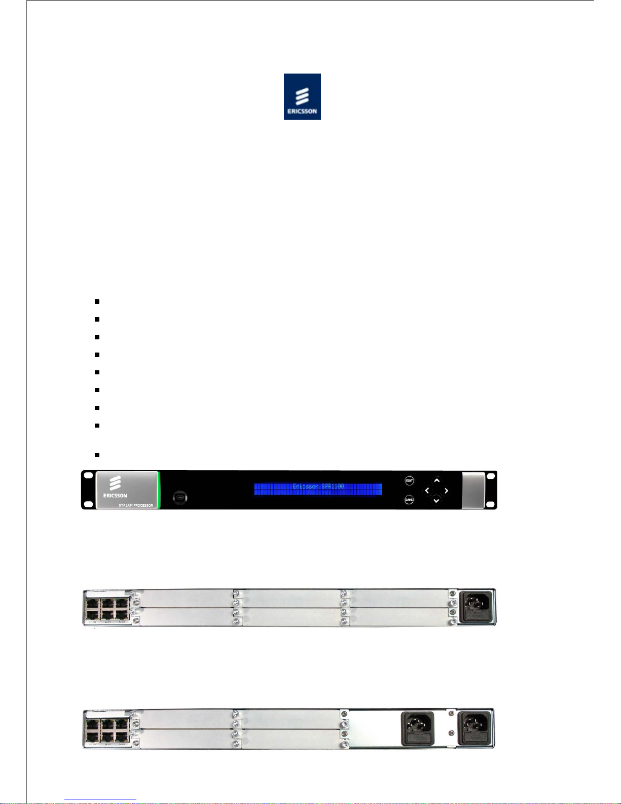
19" 1 ‘RU’ rack mount chassis.
Front panel LCD and keypad for limited control and status reporting.
Tri-colour LED to indicate chassis health.
Dual redundant Ethernet control ports.
Two pairs of dual redundant Ethernet ports for data input and output.
Single or dual AC power supply variants.
Single or dual DC power supply variants.
6 module slots (single AC or DC PSU chassis) or 4 module slots (dual AC or DC PSU
chassis)
Modules are ‘hot swappable’
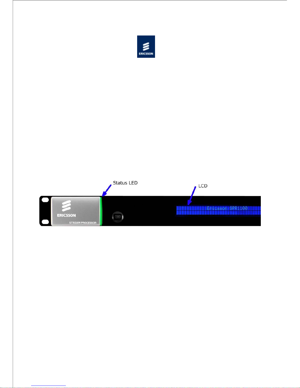
Ericsson SPR1100 Front Panel
Ericsson SPR1100 Rear Panel - Single AC Chassis
Page 19
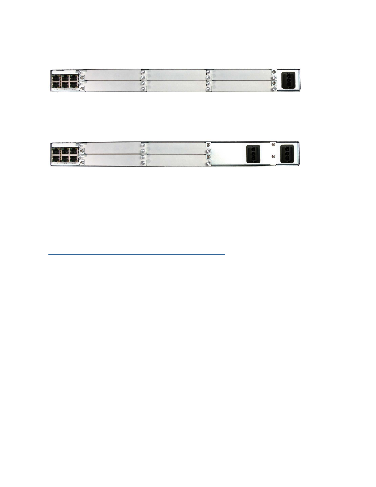
Ericsson SPR1100 Rear Panel - Dual AC Chassis
Ericsson SPR1100 Rear Panel - Single DC Chassis
Ericsson SPR1100 Rear Panel - Dual DC Chassis
NOTE:
Refer to Installing the Equipment > External Interfaces > Base Chassis for
more details of the items at the rear and front panels.
SPR11/CHASSIS/1AC 1U Base Chassis (AC)
Describes the single AC power supply base chassis.
SPR11/CHASSIS/2AC 1U Base Chassis (Dual AC)
Describes the dual AC power supply base chassis.
SPR11/CHASSIS/1DC 1U Base Chassis (AC)
Describes the single DC power supply base chassis.
SPR11/CHASSIS/2DC 1U Base Chassis (Dual AC)
Describes the dual DC power supply base chassis.
© Ericsson AB 2011. All rights reserved
Page 20

Home > SPR1100 Handbook > Introduction > Base Chassis > Base Chassis (AC)
SPR11/CHASSIS/1AC 1U Base Chassis (AC)
Overview
The Ericsson SPR1100 consists of a base chassis, a single AC mains input and up to six
modules. The base chassis is a 1 ‘RU’ 19" rack mount chassis that provides the control
interfaces, and two pairs of dual redundant Ethernet ports for data input and output.
The modules provide the video, audio and data processing functionality and can be ‘Hot
Swapped’ i.e. inserted or removed whilst the chassis is powered.
Single AC PSU Base Chassis
Front Panel
SPR11/CHASSIS/1AC Front Panel Items
LCD
Control and status information is displayed on a 2 line by 40 character display.
Buttons
Six buttons are provided for navigating through the front panel menus.
Status LED
The status LED is green when there are no active alarms or warnings and red if there is a
critical alarm.
The status LED is amber if there is an active warning, minor or major alarm.
USB Connector
Page 21
This is not for customer use.
Rear Panel
The modules, control Ethernet ports, data Ethernet ports, and the AC power input are all
accessible at the rear of the base chassis.
SPR11/CHASSIS/1AC Rear Panel Items [Single AC Chassis]
Page 22
Page 23

Ethernet Port Numbering
© Ericsson AB 2011. All rights reserved
Page 24
Home > SPR1100 Handbook > Introduction > Base Chassis > Base Chassis (Dual AC)
SPR11/CHASSIS/2AC 1U Base Chassis (Dual AC)
Overview
The Ericsson SPR1100 consists of a base chassis, dual AC inputs and up to four modules.
The base chassis is a 1 ‘RU’ 19" rack mount chassis that provides the control interfaces, and
two pairs of dual redundant Ethernet ports for data input and output.
The modules provide the video, audio and data processing functionality and can be ‘Hot
Swapped’, i.e. inserted or removed whilst the chassis is powered.
Why Have Two Mains Connectors
Many broadcasting sites have two power supply chains, either from the master switchboard
or, for major sites, from different points on the supply grid. As the most common cause of
system failure is loss of power, feeding the chassis from the separate chains ensures
reliability of supply and, therefore, continuity of service.
Dual AC PSU Base Chassis
Front Panel
SPR11/CHASSIS/2AC Front Panel Items
LCD
Control and status information is displayed on a 2 line by 40 character display.
Buttons
Six buttons are provided for navigating through the front panel menus.
Status LED
Page 25
The status LED is green when there are no active alarms or warnings and red if there is a
critical alarm.
The status LED is amber if there is an active warning, minor or major alarm.
USB Connector
This is not for customer use.
Rear Panel
The modules, control Ethernet ports, data Ethernet ports, and the AC power input are all
accessible at the rear of the base chassis.
SPR11/CHASSIS/2AC Rear Panel Items [Dual AC Chassis]
Page 26

Page 27

Ethernet Port Numbering
© Ericsson AB 2011. All rights reserved
Page 28
Home > SPR1100 Handbook > Introduction > Base Chassis > Base Chassis (DC)
SPR11/CHASSIS/1DC 1U Base Chassis (DC)
Overview
The Ericsson SPR1100 consists of a base chassis, a single DC power input and up to six
modules. The base chassis is a 1 ‘RU’ 19" rack mount chassis that provides the control
interfaces, and two pairs of dual redundant Ethernet ports for data input and output.
The modules provide the video, audio and data processing functionality and can be ‘Hot
Swapped’ i.e. inserted or removed whilst the chassis is powered.
Single DC PSU Base Chassis
Front Panel
SPR11/CHASSIS/1DC Front Panel Items
LCD
Control and status information is displayed on a 2 line by 40 character display.
Buttons
Six buttons are provided for navigating through the front panel menus.
Status LED
The status LED is green when there are no active alarms or warnings and red if there is a
critical alarm.
The status LED is amber if there is an active warning, minor or major alarm.
USB Connector
Page 29

This is not for customer use.
Rear Panel
The modules, control Ethernet ports, data Ethernet ports, and the DC power input are all
accessible at the rear of the base chassis.
SPR11/CHASSIS/1DC Rear Panel DC Power Socket
SPR11/CHASSIS/1DC DC Power Connector (end view)
SPR11/CHASSIS/1DC DC Power Connector (side view)
Page 30

Page 31

Ethernet Port Numbering
© Ericsson AB 2011. All rights reserved
Page 32

Home > SPR1100 Handbook > Introduction > Base Chassis > Base Chassis (Dual DC)
SPR11/CHASSIS/2DC 1U Base Chassis (Dual DC)
Overview
The Ericsson SPR1100 consists of a base chassis, two DC power inputs and up to four
modules. The base chassis is a 1 ‘RU’ 19" rack mount chassis that provides the control
interfaces, and two pairs of dual redundant Ethernet ports for data input and output.
The modules provide the video, audio and data processing functionality and can be ‘Hot
Swapped’ i.e. inserted or removed whilst the chassis is powered.
Dual DC PSU Base Chassis
Front Panel
SPR11/CHASSIS/2DC Front Panel Items
LCD
Control and status information is displayed on a 2 line by 40 character display.
Buttons
Six buttons are provided for navigating through the front panel menus.
Status LED
The status LED is green when there are no active alarms or warnings and red if there is a
critical alarm.
The status LED is amber if there is an active warning, minor or major alarm.
USB Connector
Page 33

This is not for customer use.
Rear Panel
The modules, control Ethernet ports, data Ethernet ports, and the DC power inputs are all
accessible at the rear of the base chassis.
SPR11/CHASSIS/2DC Rear Panel DC Power Socket
SPR11/CHASSIS/2DC DC Power Connector (end view)
SPR11/CHASSIS/2DC DC Power Connector (side view)
Page 34

Page 35

Ethernet Port Numbering
© Ericsson AB 2011. All rights reserved
Page 36

Home > SPR1100 Handbook > Introduction > Transcoder Cards
Transcoder Modules
The following transcoder module is supported in this release:
MPM1 HD/SD Transcoder (SPR/HWO/MPM1)
This card can transcode up to 12 standard definition or up to 4 high definition video inputs
using MPEG-2 or H.264 encoding, and can compress up to 24 audio streams, depending on
audio encoding mode.
© Ericsson AB 2011. All rights reserved
Page 37

Home > SPR1100 Handbook > Introduction > Transcoder Cards > MPM1 Transcoder Card
Media Processing Module (MPM1)
The MPM1 Transcoder Card has a unique processing engine that extracts the maximum
efficiency possible from the MPEG2 and H.264 specifications.
Summary of Features
Video Transcoding
Describes the Video processing functionality available in the MPM1.
Audio Transcoding
Describes the Audio Inputs and Coding Modes provided by the MPM1.
Data Processing
Describes the data extraction and processing capabilities of the MPM1
© Ericsson AB 2011. All rights reserved
Page 38

Summary of Features
Overview
The media processing module is a single slot solution which can transcode multiple MPEG-2
and/or H.264 video streams, at both SD and HD resolutions. Audio passthrough and
transcode functionality is also supported.
The total maximum number of transcodes per module is related to the resolution.
At SD resolution, each MPM1 can perform 12 simultaneous transcodes.
Each transcode involving a HD-resolution stream on input and/or output reduces the
number of possible SD transcodes by 3
Maximum number of SD-to-SD transcodes
Maximum number of HD transcodes
1209
1
62330
4
Video Formats
Profiles Supported
MPEG-4 AVC (H.264) Main Profile @ Level 3 to Level 4.1 (0.500 to 12.5 Mbps)
MPEG-4 AVC (H.264) High Profile @ Level 4.0 to Level 4.1 (1.000 to 20.0 Mbps)
MPEG-2 MP@ML Video (1.000 to 15.0 Mbps)
MPEG-2 MP@HL Video (2.000 to 30.0 Mbps)
SD Resolutions Supported
720 x 576 @ 25Hz
704 x 576 @ 25Hz
640 x 576 @ 25Hz
544 x 576 @ 25Hz
528 x 576 @ 25Hz
Page 39

480 x 576 @ 25Hz
352 x 576 @ 25Hz
720 x 480 @ 29.97Hz
704 x 480 @ 29.97Hz
640 x 480 @ 29.97Hz
544 x 480 @ 29.97Hz
528 x 480 @ 29.97Hz
480 x 480 @ 29.97Hz
352 x 480 @ 29.97Hz
HD Resolutions Supported
1280 x 720 @ 50Hz
960 x 720 @ 50Hz
1920 x 1080 @ 25Hz
1440 x 1080 @ 25Hz
1280 x 1080 @ 25Hz
1280 x 720 @ 59.94Hz
960 x 720 @ 59.94Hz
1920 x 1080 @ 29.97Hz
1440 x 1080 @ 29.97Hz
1280 x 1080 @ 29.97Hz
1920 x 1080 @ 23.976Hz
Video PIP Formats
MSTV
128 x 96 @ 25Hz
128 x 96 @ 29.97Hz
96 x 96 @ 25Hz
96 x 96 @ 29.97Hz
non-MSTV
192 x 192 @ 25Hz
192 x 192 @ 29.97Hz
144 x 144 @ 25Hz
144 x 144 @ 29.97Hz
Audio Formats
Supported audio decoding and encoding modes:
Page 40

- MPEG-1 Layer II (32 kbps to 384 kbps)
- MPEG-2 Layer II (32 kbps to 384 kbps)
- Dolby Digital 2.0, 5.1 (56 kbps to 640 kbps)
- MPEG-4 AAC/AAC-LC/HE-AAC (16-256kbps)
Audio Transcoding
The MPM supports transcoding between any of the supported formats.
The maximum number of simultaneous transcodes per card is summarised in the Audio
Transcoding page
VBI Passthrough
In addition to Audio and Video Transcoding, data may be passed through from Input to
Output. Typically, this can include :
Generic VANC carriage (SMPTE 2038)
VBI in PID
Teletext
DVB Subtitles
AFD
SCTE 35 Splicepoint Pass-Through
The MPM supports SCTE 35 pass-through. SCTE 35 may be added to any output stream by
dragging the component to the appropriate stream in the Services Configuration page. The
video will have the appropriate splice-points re-inserted at the right points on transcode.
© Ericsson AB 2011. All rights reserved
Page 41

Home > SPR1100 Handbook > Introduction > Transcoder Cards > MPM1 Transcoder Card > MPM1 Video
Transcoding
MPM1 Video Transcoding
Inputs and Outputs
The MPM1 Transcoder has no external inputs or outputs. All data is passed into and out of
the module via the internal connectors.
Overview
The MPM1 can transcode up to twelve SD-to-SD streams or up to four transcodes with HD
streams on input and/or output, or a combination of both. Each high-definition stream
reduces the maximum number of standard-definition streams by three
Video Compression Functionality
The supported formats and bit rates are summarised in the Coded Elementary Stream page
Any supported video format can be transcoded to any other supported video format, with
the following exceptions:
720p outputs can only be transcoded from 720p inputs
1080PsF outputs can only be transcoded from 1080PsF inputs
720p inputs cannot be transcoded into 1080i outputs
Any supported PIP format can be generated from any supported input video format
Loss of Video Input
On loss of video input, the MPM1 can be configured to select one of the default test patterns
or a freeze frame as the output.
© Ericsson AB 2011. All rights reserved
Page 42

Home > SPR1100 Handbook > Introduction > Transcoder Cards > MPM1 Transcoder Card > Audio Transcoding
MPM1 Audio Transcoding
Overview
Audio data comes to the MPM by way of the internal data connections, in just the same way
as the video.
The maximum number of simultaneous audio transcodes that can be performed on a MPM is
summarised below. It is possible to mix different audio transcodes on a module, in which
case the maximum number of transcodes must be scaled accordingly.
Outputs
Inputs
MPEG-
1L2
Dolby
Digital 2.0
Dolby
Digital 5.1
AAC/HE-
AAC 2.0
AAC/HE-
AAC 5.1
MPEG-1L2
2412n/a24n/a
Dolby Digital
2.0/5.1
18126126
AAC/HE-AAC
2.0/5.1
12126126
For example, per module, it is possible to transcode
24xMPEG L2
to
MPEG L2
or 12x
AACtoMPEG L2
or 18x
MPEG L2
to
MPEG L2
and3x
AACtoMPEG L2
Audio Pass-Through
Audio streams can be passed through directly from the input without re-encoding (passthrough mode). No audio licenses are required for this mode.
© Ericsson AB 2011. All rights reserved
Page 43

Home > SPR1100 Handbook > Introduction > Transcoder Cards > MPM1 Transcoder Card > Data Processing
Data Processing
Data Component Pass-Through
Data of any type can be passed through from the Input Transport Stream to the Output
Transport Stream.
NOTE:
Closed-Caption Data is handled slightly differently from other data types, and
will be automatically transcoded as necessary.
© Ericsson AB 2011. All rights reserved
Page 44

Home > SPR1100 Handbook > Installing the Equipment
Installing the Equipment
This chapter provides a guide to the suitability of an installation and gives detailed
procedures for the preparation and installation of the equipment. Also details the external
connectors and provides important safety information.
Preliminary Checks
Gives general information relating to Mechanical Inspection of the unit and how to move it
safely.
Site Requirements
Describes the requirements for powering the unit and the need for lightning protection (if
required).
Mounting in a Rack
Gives information associated with fixing the unit into a rack and the care and positioning of
cables.
External Interfaces
Describes the connectors relating to the base chassis.
© Ericsson AB 2011. All rights reserved
Page 45

Home > SPR1100 Handbook > Installing the Equipment > Preliminary Checks
Preliminary Checks
Mechanical Inspection
When taking delivery of an Encoder, check the equipment items delivered against the
enclosed delivery note. Inspect the equipment for damage-in-transit. If in doubt, please
contact Customer Services.
WARNING!
Removing the covers of this equipment may invalidate any warranties, cause a safety
hazard or/and affect the EMC performance. Check with Customer Services.
Moving the Equipment Safely
Do not place this product on an unstable cart, stand, bracket, or table. The product may fall,
causing serious injury and serious damage to the product. Use only with a cart, stand,
bracket or table recommended by Ericsson.
An appliance and cart combination should be moved with care. Quick stops, excessive force,
and uneven surfaces may cause the appliance and cart combination to overturn.
Do not move or carry the equipment whilst it is still connected to the supply or other leads,
is live or is in operation.
See, also:
The Handling and Lifting section in Read This First!
Appendices > Handling Option Cards > Handling Option Cards
© Ericsson AB 2011. All rights reserved
Page 46

Home > SPR1100 Handbook > Installing the Equipment > Site Requirements
Site Requirements
This chapter provides a guide to the suitability of an installation and gives detailed
procedures for the preparation and installation of the equipment. Also details the external
connectors and provides important safety information.
AC Power Supply
Gives information relating to the AC power inlet and associated components.
DC Power Supply
Gives information relating to the DC power inlet and associated components.
Power Consumption
Details the power consumption of the base chassis and each transcoder module.
Protective and Technical Earths
Describes the requirements for earthing the unit.
Lightning Protection
This topic discusses the requirement of lightning protection (when appropriate).
© Ericsson AB 2011. All rights reserved
Page 47

Home > SPR1100 Handbook > Installing the Equipment > Site Requirements > AC Power Supply
AC Power Supply
Variants
This Handbook covers two Base Chassis; a single AC PSU version, and a dual AC PSU
version.
Dual AC Power
[Single AC PSU]
[Dual AC PSU]
AC Power Receptacles
Specification
The equipment operates from an wide-ranging mains power supply (100-240 V AC 50/60 Hz
nominal) and is designed for use in ambient air temperature in the range 0°C to +50°C.
There are no links etc. to be altered for operation from different supply voltages. The full
Technical Specification is given in Technical Specification > Chassis [Host] > Power Supplies.
WARNING!
The following points regarding power connection must be adhered to ensure safe operation
of the equipment.
The equipment should only be operated from the type of power source indicated on the
marking label. If you are not sure of the type to your business, consult your appliance
dealer or local power company. Do not overload wall outlets and extension cords as this
can result in a risk of fire or electric shock.
1.
Page 48

The equipment is not fitted with an AC Power On/Off switch. Ensure the supply socket
outlet is installed or located near the equipment so that it is accessible.
2.
Remove both sources of mains power to the dual PSU version before removing covers or
moving the equipment.
3.
Supply Cord
A two-metre mains supply cord is supplied with this product. It is fitted with a moulded plug
suitable for the USA, UK or mainland Europe as advised at the time of ordering.
Wire Colours
The wires in the supplied cord are coloured as follows:
UK (BS 1363)
EUROPE (CEE
7/7)
USA (NEMA 515P)
Earth
Green and
yellow
Green and
yellow
Green
Neutral
Blue
Blue
White
Live
Brown
Brown
Black
Connecting the Equipment to the AC Power Supply
As there is no mains power switch fitted to this chassis, ensure the local AC power supply is
switched OFF before connecting the supply cord.
Connect the mains lead to the equipment and then to the local supply.
© Ericsson AB 2011. All rights reserved
Page 49

Home > SPR1100 Handbook > Installing the Equipment > Site Requirements > DC Power Supply
DC Power Supply
Variants
This Handbook covers two types of DC Base Chassis; a single DC PSU version, and a dual
DC PSU version.
DC Power Connector
Specification
The equipment operates from a -48V DC power supply and is designed for use in ambient
air temperature in the range 0°C to +50°C. There are no links etc. to be altered for
operation from different supply voltages. The full Technical Specification is given in Technical
Specification > Chassis [Host] > Power Supplies.
WARNING!
The following points regarding power connection must be adhered to ensure safe operation
of the equipment.
This equipment is Class 1 and must have a protective earth.1.
The equipment should only be operated from the type of power source indicated on the
marking label. If you are not sure of the type to your business, consult your appliance
dealer or local power company. Do not overload wall outlets and extension cords as this
can result in a risk of fire or electric shock.
2.
The equipment is not fitted with an DC Power On/Off switch. Ensure the supply socket3.
Page 50

outlet is installed or located near the equipment so that it is accessible.
3.
Remove both sources of power to the dual PSU version before removing covers or moving
the equipment.
4.
Wire Colours
The wires in the supplied cord are coloured as follows:
Earth
Green and yellow
-48V
Blue
0V
Brown
Connecting the Equipment to the DC Power Supply
NOTE:
This equipment is not intended for direct connection to centralised DC power
systems in the USA or Canada.
This equipment does not have an input fuse. For protection of the DC wiring, a circuit
breaker of maximum 16A is recommended.
For wiring DC power, a minimum wire size of 1.0mm2 (17AWG) is recommended. This may
need to be increased for longer cable runs.
As there is no power switch fitted to this chassis, ensure the local DC power supply is
switched OFF before connecting the supply cord.
Connect the power lead to the equipment and then to the local supply.
© Ericsson AB 2011. All rights reserved
Page 51

Home > SPR1100 Handbook > Installing the Equipment > Site Requirements > Power Consumption
Power Consumption
Rated current 4.0 – 2.0 A
Power consumption: 350W (Actual power consumption is dependant on the hardware
options selected, see Table of Typical Power Consumption).
Typical Power Consumption
Item
Description
Power
SPR11/CHASSIS/1AC
1U Base Chassis (AC)
70 W
SPR11/CHASSIS/2AC
1U Base Chassis (Dual
AC)
80 W
SPR/HWO/MPM1
MPM1 HD/SD
Transcoders (6 cards)
250 W
See also Technical Specification>Chassis>Power Supplies, Technical Specification>*
Transcoder>Power Supplies.
© Ericsson AB 2011. All rights reserved
Page 52

Home > SPR1100 Handbook > Installing the Equipment > Site Requirements > Protective and Technical Earths
Protective and Technical Earths
Protective Earth
WARNING!
This unit must be correctly earthed as described below.
This unit must be correctly earthed through the moulded plug supplied. If the local mains
supply does not have an earth conductor do not connect the unit. Contact Customer
Services for advice.
1.
Before connecting the unit to the supply, check the supply requirements.2.
Technical Earth
The terminal marked at the rear panel is a Technical Earth. Its use is recommended. This is
NOT a protective earth for electric shock protection.
Technical Earth
The Technical Earth provides a suitable connection between the equipment and the
Page 53

installation to give a low impedance path at normal operating frequencies.
The terminal is provided to:
Ensure all equipment chassis fixed within a rack are at the same technical earth potential.1.
Eliminate the migration of stray charges when connecting between equipment.2.
To do this, connect a wire between the Technical Earth terminal and a suitable point on the
rack.
CAUTION!
It is strongly recommended that the earth terminal at the rear panel of the equipment is
connected to a site Technical Earth before any external connections are made and the
equipment is powered. This limits the migration of stray charges.
© Ericsson AB 2011. All rights reserved
Page 54

Home > SPR1100 Handbook > Installing the Equipment > Site Requirements > Lightning Protection
Lightning Protection
WARNING!
If the equipment has been subject to a lightening strike or power surge, which has stopped
it working, disconnect the power immediately, do not re-apply power until it has been
checked for safety. If in doubt, contact Customer Services.
Where appropriate, ensure this product has an adequate level of lightning protection.
Alternatively, during a lightning storm or when it is left unattended and unused for long
periods of time, unplug it from the supply outlet and disconnect the output equipment. This
prevents damage to the product due to lightning and power line surges.
© Ericsson AB 2011. All rights reserved
Page 55

Home > SPR1100 Handbook > Installing the Equipment > Mounting in a Rack
Mounting in a Rack
Gives information associated with fixing the unit into a rack and the care and positioning of
cables.
Installing the Equipment
Read This First: Read the information contained in this topic before beginning to install the
equipment.
Care in Positioning
This topic describes what needs to be considered before fixing the unit into a rack.
Fixing
Provides information related to the fixing of the unit in a rack.
Cable Types/Installing Cables
Tabulates the recommended cables required to maintain EMC compliance. Also describes the
care required when installing the cables.
© Ericsson AB 2011. All rights reserved
Page 56

Home > SPR1100 Handbook > Installing the Equipment > Mounting in a Rack > Installing the Equipment
Handling and Lifting
Handling the Equipment
The equipment must be handled and installed carefully and thoughtfully to prevent safety
hazards and damage.
Lifting
In some circumstances the unit might be awkward to lift. In which case, do not attempt to
lift or move it without proper assistance or equipment. If in doubt, seek assistance.
Electrostatic Handling
WARNING!
Static electricity can damage electronic components. To avoid damage, keep option cards in
their static-protective package until you are ready yo install them.
Refer to Options Cards for information relating to the handling of Option Modules.
Installing the Equipment
Read the comments in Read This First before starting work.
© Ericsson AB 2011. All rights reserved
Page 57

Home > SPR1100 Handbook > Installing the Equipment > Mounting in a Rack > Care in Positioning
Care in Positioning
Positioning the Unit
CAUTION!
The following points must be taken in to consideration when positioning the unit.
The fans contained within this unit are not fitted with a dust/insect filter. Pay attention to
the environment in which it is to be used.
1.
Do not install units so that the air intake of one aligns with the outlet on another. Provide
baffles and adequate spacing.
2.
The equipment should never be placed near or over a radiator or other source of heat. It
should not be placed in a built-in installation such as a rack unless proper ventilation is
provided and the instructions have been adhered to.
Allow at least 40 mm free air-space at each side of the equipment to ensure adequate
cooling.
Racks containing stacked equipment may need to be forced air-cooled to reduce the
ambient temperature within the rack.
Protection from Moisture
Do not install this equipment in areas of high humidity or where there is a danger of water
ingress.
Cooling
Side openings in the unit, as well as side-mounted cooling fans, are provided for ventilation.
They ensure reliable operation of the product and protect it from overheating.
Page 58

Airflow Through the Unit
WARNING!
The ventilation openings must not be blocked or covered.
© Ericsson AB 2011. All rights reserved
Page 59

Home > SPR1100 Handbook > Installing the Equipment > Mounting in a Rack > Fixing
Fixing
Overview
The equipment is designed for fixed use only and has been shipped with fixing brackets
suitable for a standard 19-inch rack. When installed in a rack, it should be secured using the
fixing brackets. In addition, support shelves must be used to reduce the weight on the
brackets. Ensure it is firmly and safely located and it has an adequate flow of free-air.
Fixing the Unit
Slide the unit onto the chassis supports and affix to the rack by means of an M6 x 18 mm
panhead screw in each corner.
A freestanding unit should be installed on a secure horizontal surface where it is unlikely to
be knocked or its connectors and leads disturbed.
© Ericsson AB 2011. All rights reserved
Page 60

Home > SPR1100 Handbook > Installing the Equipment > Mounting in a Rack > Cable Types/Installing Cables
Cable Types/Installing Cables
Cable Types
The signal cable types (or similar) described in the following table are those recommended
by Ericsson in order to maintain product EMC compliance.
Signal Type
Connector
Cable
Ethernet (Control)
RJ-45
Alcatel Data Cable FTP 7 x 0.16
Ethernet (Data)
RJ-45 Cat 5e
Belden Datatwist (S-FTP)
Installing Cables – Safely
Power supply cables should be routed so that they are not likely to be walked on or pinched
by items placed upon or against them. Pay particular attention to cables at plugs,
convenience receptacles, and the point where they exit from the appliance.
Do not run AC power cables in the same duct as signal leads.
Do not move or install equipment whilst it is still attached to the mains supply.
Ensure safety and ESD precautions are observed whilst inter-connecting equipment.
© Ericsson AB 2011. All rights reserved
Page 61

Home > SPR1100 Handbook > Installing the Equipment > External Interfaces
External Interfaces
Describes the connectors and visual indicators associated with each component of the
equipment.
Base Chassis
Identifies and describes each connector and indicator associated with the Chassis.
© Ericsson AB 2011. All rights reserved
Page 62

Home > SPR1100 Handbook > Installing the Equipment > External Interfaces > Base Chassis
Chassis/Host
General
Identifies the position of the connectors and indicators at the front and rear panels and what
combinations of external interfaces are supported.
Control Ethernet
Identifies the Ethernet Control ports located at the rear panel of the chassis and tabulates
the connectors' pinout. Describes the operation of each port, and the Status and Activity
indicators.
Data Ethernet
Identifies the Ethernet Data ports located at the rear panel of the chassis and tabulates the
connectors' pinout. Describes the operation of each port, and the Status and Activity
indicators.
AC Input Connector
Shows the rear panel AC connector and provides fusing information.
DC Input Connector
Shows the rear panel DC connector.
USB Connector
Provides information associated with the USB connector located at the front panel.
© Ericsson AB 2011. All rights reserved
Page 63

Home > SPR1100 Handbook > Installing the Equipment > External Interfaces > Base Chassis > General
General
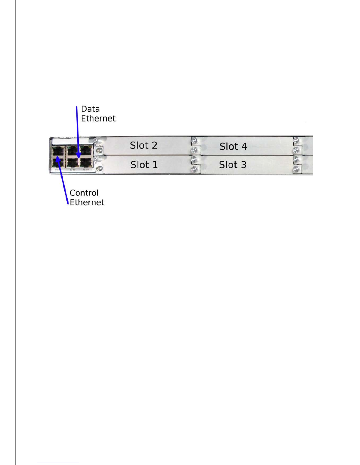
1 ‘RU’ Base Chassis Single PSU Rear Panel
WARNING!
It is strongly recommended that the terminal marked at the rear panel of the equipment is
connected to a site Technical Earth before any external connections are made and the
equipment is powered. This limits the migration of stray charges.
Location of the Ethernet and Single AC Connectors at the Rear Panel
All signal connections are made via the rear panel.
NOTE:
Single AC PSU version shown.
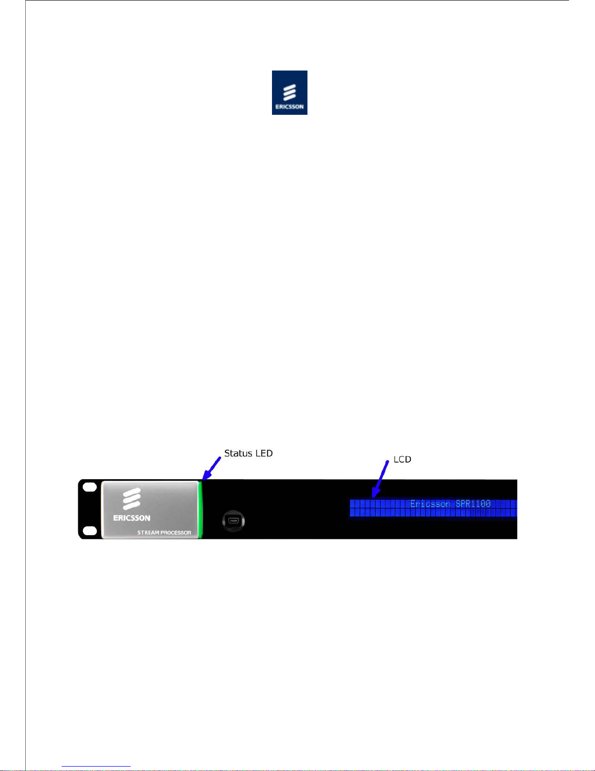
Front Panel
Identifying Items Located at the Front Panel
The front panel provides a 2 line by 40 character display, 6 buttons, and a red/amber/green
Page 64

tri-colour status LED.
Items on the Front Panel
LCD
Control and status information is displayed on a 2 line by 40 character display.
Buttons
Six buttons are provided for navigating through the front panel menus. See Front Panel
Controls and Pushbuttons for more details.
Status LED
An LED located at the front panel gives an indication of the status of the unit.
LED
State
Unit Status
Off
Unit not powered
Green
No active warnings or alarms
Amber
Active warning/s, minor or major
alarm/s
Red
Active critical alarm/s
USB Connector
This is not for customer use. Please refer to USB connector .
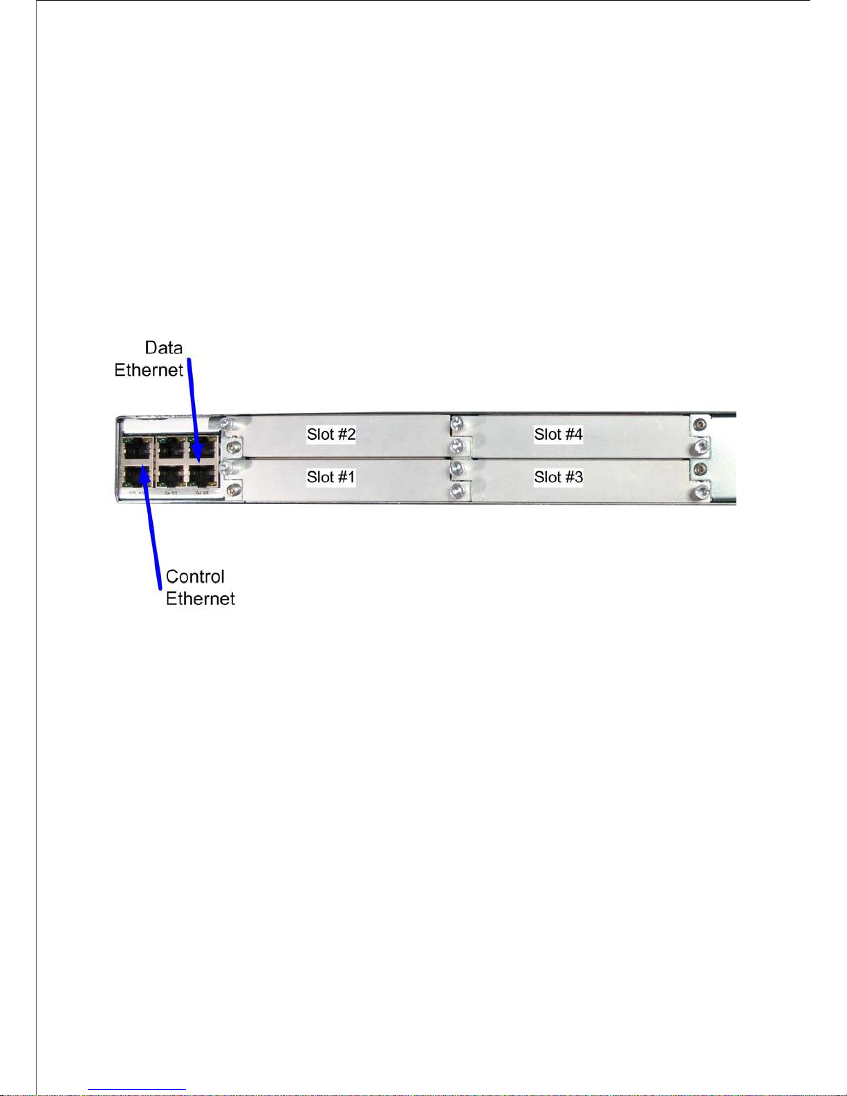
1 ‘RU’ Base Chassis Dual PSU Rear Panel
This chassis is the same as the 1 ‘RU’ Base Chassis but with the dual PSU.
Data Ethernet
Page 65

Control Ethernet
AC Input
Location of the Ethernet and Dual AC Connectors at the Rear Panel (Blanking Plates Fitted)
A technical specification for the connections is given in Technical Specification > Base
Chassis .
© Ericsson AB 2011. All rights reserved
Page 66

Home > SPR1100 Handbook > Installing the Equipment > External Interfaces > Base Chassis > Control Ethernet
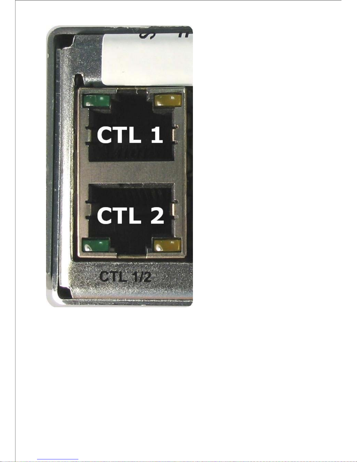
Control Ethernet
Overview
The Ethernet control ports are used to connect the equipment to a PC for access with a web
browser.
Page 67

Ethernet Ctrl Port Numbering
Both connectors share the same IP address, Ctrl1 is the Primary control port, and is by
default the active control port. Control Port Ctrl2 should be considered as the secondary
control network as it will not respond to the Control Port IP Address unless control has been
passed to it either as a result of a redundancy switch, or via a user command. The active
control port switches when Ctrl1 has no link (e.g. carrier), and Ctrl2 has the link.
Refer to:
Operation and Control >Basic Functions > Ethernet: Control for Control Port Parameters.
NOTE:
This equipment can be controlled using a single control
connection.
Page 68

Item
Specification
Connector type
RJ-45 (100/1000 Base T)
Connector designation
Ctl 1/2
Pin outs
(Unused pins are not connected)
Pin 1 - Tx Out(+)
Pin 2 - TX Out (-)
Pin 3 - Rx In (+)
Pin 6 - RX Out (-)
Status and Activity Indication
Each Ethernet Control Port has a rear panel mounted status LEDs associated with it to
indicate link status, activity and speed as follows:
Left (Green) LED
Port
Status
Link
Speed
LED Status
Active
Port
No Link
Off
- - - - - - - - - - - -
- - - - - -
100 Mbps
Flash Off
x 2
- - -
-
1000
Mbps
Flash Off
x 3
- - - -
- -
Spare
Port
No Link
Off
- - - - - - - - - - - -
- - - - - -
100 Mbps
Flash On
x 2
- - - - - - - -
- - - - - -
1000
Mbps
Flash On
x 3
- - - - - - -
- - - - -
The Right LED flash sequence period is 1 s, with the short flash duration being 100 ms.
Page 69

Right (Yellow) LED
Link
Activity
LED Status
No Link
Off
- - - - - - - - - - - - - - - - -
-
Link
On
Activity
Flash
- - - - - -
-
© Ericsson AB 2011. All rights reserved
Page 70

Home > SPR1100 Handbook > Installing the Equipment > External Interfaces > Base Chassis > Data Ethernet
Data Ethernet
Overview
The unit has four Ethernet ports - two for data input, and two for data output and will
respond to ARPs, pings and other low-level Ethernet traffic. The ports are accessible via RJ45 connectors on the rear panel of the chassis. These are labeled Ge 1, Ge 2, Ge 3 and Ge
4.
Ge 1 and Ge 2 are used for data input, while Ge 3 and Ge 4 are data output.
Data Port Numbering
Page 71

Item
Specification
Connector type
RJ-45 (100/1000 Base T)
Connector designation
Ge 1 /2 Ge 3 /4
Pin outs
(Unused pins are not connected)
Pin 1 - Tx Out(+)
Pin 2 - TX Out (-)
Pin 3 - Rx In (+)
Pin 6 - RX Out (-)
Status and Activity Indication
Each Ethernet Data Port has a rear panel mounted status LED associated with it to indicate
link status, activity and speed as follows:
Left (Green) LED
Link Speed
LED Status
No Link
Off
- - - - - - - - - - - - - - -
- - 100 Mbps
Flash Off x 2
- - - -
1000 Mbps
Flash Off x 3
- - - - - -
The left LED flash sequence period is 1 s, with the short flash duration being 100 ms.
Right (Yellow) LED
Link Activity
LED Status
No Link
Off
- - - - - - - - - - - - - -
- - - Link
On
Activity
Flash
- - - - -
Refer to:
Operation and Control > Ethernet Data for Control Port Parameters.
Page 72

Appendices > Technical Specification > Chassis (Host) > Data Ethernet Specification for the
electrical characteristics.
© Ericsson AB 2011. All rights reserved
Page 73

Home > SPR1100 Handbook > Installing the Equipment > External Interfaces > Base Chassis > AC Input
Connector
Power Requirements
AC Connector
The AC input connector is as follows:
Item
Description/Specification
Connector
Mains input filter with CEE 22/IEC320
plug
Fusing
Fuse in live conductor in mains input
filter
Fuse type
Time delay (T) 1500 A High breaking
capacity (HBC)
AC Power
AC Power Inlets
AC Input
Refer to:
Technical Specification > Base Chassis > Power Supply
Installing the Equipment > Site Requirements > AC Power Supply
Installing the Equipment > External Interfaces > Base Chassis > AC Input
Connector
Page 74

© Ericsson AB 2011. All rights reserved
Page 75

Home > SPR1100 Handbook > Installing the Equipment > External Interfaces > Base Chassis > DC Input
Connector
Power Requirements
DC Connector
The DC input connector is as follows:
Item
Description/Specification
Connector
AMP Universal MATE-N-LOK 1-480700-0
Molex MLX 50-84-1030
Fusing
Not fused.
DC Power Inlets
DC Input
Refer to:
Technical Specification > Base Chassis > Power Supply
Installing the Equipment > Site Requirements > DC Power Supply
© Ericsson AB 2011. All rights reserved
Page 76

Home > SPR1100 Handbook > Installing the Equipment > External Interfaces > Base Chassis > USB Connector
USB Connector
The USB connector on the front panel of the unit is not for customer use.
USB Connector
This connector is only used for Test/Maintenance purposes.
© Ericsson AB 2011. All rights reserved
Page 77

Home > SPR1100 Handbook > Getting Started
Getting Started
Before any communication can be made with the unit the Control IP address needs to be
configured. The topics in this section will guide you through the process.
Setting the IP address
Describes how to set the required IP Address from the Front Panel.
IP address Ranges
This topic shows a table of allocated IP addresses adhering to the RFC3330 range of
restrictions .
Manual configuration via the web pages
The unit has been designed to be configured and controlled by way of a web interface.
© Ericsson AB 2011. All rights reserved
Page 78

Home > SPR1100 Handbook > Getting Started > Setting the IP Address
Setting the Required IP Address from the Front Panel
Power on the unit
Wait for initialisation to complete (approximately 1.5 minutes, depending on the
number of options fitted in the chassis).
Press the Right arrow pushbutton until the IP address is displayed, press edit and
then use the up/down/right/left arrow pushbuttons to set the required IP address
- Right/left pushbuttons will move the cursor between characters
- Up/down pushbuttons will increase/decrease the number selected by the cursor
Press save to store the new IP address.
Continue and set the subnet mask and gateway address in the same way using the
down pushbutton to reach each parameter.
NOTE:
IP Address range 192.168.10.x (subnet 255.255.255.0) is used for internal
unit communications, so should not be used for external communications.
Refer to Operation and Control > Front Panel for more details describing Front Panel
features.
NOTE:
A pushbutton is illuminated when there is functionality available. If a
pushbutton is not illuminated, pressing it will have no effect.
© Ericsson AB 2011. All rights reserved
Page 79

Home > SPR1100 Handbook > Getting Started > IP Address Ranges
IP Address Restrictions
IP Addresses on the unit must adhere to RFC3330 range of restrictions as listed in the
following table of allocated IP addresses.
Address Block
Present Use
Reference
0.0.0.0/8
"This" Network
[RFC1700, p4]
10.0.0.0/8
Private-Use Networks
[RFC1918]
14.0.0.0/8
Public-Data Networks
[RFC1700, p181]
24.0.0.0/8
Cable Television Networks
---
39.0.0.0/8
Reserved but subject to
allocation
[RFC1797]
127.0.0.0/8
Loopback
[RFC1700, p5]
128.0.0.0/16
Reserved but subject to
allocation
---
169.254.0.0/16
Link Local
---
172.16.0.0/12
Private-Use Networks
[RFC1918]
191.255.0.0/16
Reserved but subject to
allocation
---
192.0.0.0/24
Reserved but subject to
allocation
---
192.0.2.0/24
Test-Net
---
192.88.99.0/24
6to4 Relay Anycast
[RFC3068]
192.168.0.0/16
Private-Use Networks
[RFC1918]
198.18.0.0/15
Network Interconnect Device
Benchmark Testing
[RFC2544]
223.255.255.0/24
Reserved but subject to
allocation
---
224.0.0.0/4
Multicast
[RFC3171]
240.0.0.0/4
Reserved for Future Use
[RFC1700, p4]
Page 80

NOTE:
The control network and data networks should not conflict. It is suggested
that the ranges for these networks are in the Private-Use Networks as listed in
the summary Table.
IP Address range 192.168.10.x (subnet 255.255.255.0) is used for internal
unit communications, so should not be used for external communications.
© Ericsson AB 2011. All rights reserved
Page 81

Manual Configuration via the Web Pages
The Ericsson SPR1100 has been designed to be configured and controlled by its own web
interface, which is described here.
The main Transcode Configuration page can be found by the following navigation :
Configure > Services
1) Configure Input Streams
The left-hand panel of the Transcode page defines the input Transport Streams to be
processed by the unit.
Page 82

Transport Streams are grouped by Physical Interface. Each Transport Stream is defined by
its IP address and port number. Multiple services can reside within each transport stream,
with multiple components within each service.
The tree of input streams is navigated by expanding and contracting items using the and
buttons alongside. All entries within an item can be expanded by right-clicking on that
item and selecting Expand All .
Selecting an item (by clicking on it) causes the relevant properties for that item to be
displayed in the "Properties" panel. Properties that cannot be edited will be "greyed out".
Transport streams may be added to a Data Interface by right-clicking on the interface entry
and selecting Add transport stream .
2) Configure Output Streams
The second panel from the left defines the output Transport Streams that will be produced
Page 83

by the unit.
Transport Streams are again grouped by Physical Interface. Each transport Stream has an
IP address and port number, and can contain multiple services, with multiple components in
each service.
Transport Streams may be added in several ways:
Right-clicking the Output Interface and selecting Add transport stream .
Dragging streams or services from the Inputs panel and dropping them onto an
appropriate place in the heirarchy of the Outputs panel.
NOTE:
Each input service may be used in up to two independent (and different)
transcode operations. This is achieved by dragging the same input service to
multiple output multicasts. Each transcode will require a separate license.
Output services can be duplicated up to four times, so that the same transcode operation
can be included in up to four output Transport Streams. This is achieved by right-clicking on
Page 84

the output service and selecting "Duplicate Selected on output".
3) Configure the Transcode Operations
Each item in the Outputs panel can be configured at its position in the heirarchy. This allows
the operator to configure all dependent items together; for example, selecting a transport
stream would allow all services within that transport stream to be configured together.
Individual components can also be altered if a common configuration is not desired.
Page 85

For each item selected, a number of panes will appear in the Properties panel. These
include:
Transport Stream
Service
Video Component
Video PIP Component
Audio Component
Not all of these will be available for every component.
Each pane of the configuration may have several sets of parameters that may be
configured. These are arranged in a tabbed interface within the pane.
Page 86

4) Warnings, Errors and History
At the bottom of the Services Configuration page is an "Information" panel. This can show
Warnings, Errors, or Change History according to the tab selection on the left hand side
5) Allocation Status
With the very dense transcode configurations possible with the Ericsson SPR1100, it is all
too easy to lose track of exactly how much of the unit's resource has been used.
To assist the operator in managing the total allocation usage, the Services Configuration
page has an Allocation pane to show the amount of resource allocated or available with the
configuration currently set up on the page.
If more detail is required, the panel has a "Details" tab which will show the
allocated/available breakdown for each transcode type.
6) Apply Configuration
Page 87

All configuration changes initially only occur in the User Interface. The Ericsson SPR1100
does not change its behaviour until the operator presses the "Apply All" button.
Once the configuration is applied, the unit is updated with the new configuration.
NOTE:
Changing the configuration may cause output glitching. This is kept to a
minimum; transcoder units which do not need reconfiguration will not be
interrupted. Additionally, changing the output bit rate will not cause a glitch.
© Ericsson AB 2011. All rights reserved
Page 88

Home > SPR1100 Handbook > Transport Stream Output
Transport Stream Output
Output
Gives information relating to the Transport Stream from the unit.
Transport Stream
Gives information relating to the components of the transport stream.
© Ericsson AB 2011. All rights reserved
Page 89

Home > SPR1100 Handbook > Transport Stream Output > Output
Transport Stream Output Overview
Gives the extent of MPEG-2 compliancy and an overview of the Transport Streams.
Describes the TS IP Output Parameters, and states the Transport Stream and Output Data
rates.
IP Port
Gives an overview of the IP Encapsulator functional block.
Pro-MPEG FEC
Gives a brief explanation of Pro-MPEG FEC
© Ericsson AB 2011. All rights reserved
Page 90

Home > SPR1100 Handbook > Transport Stream Output > Output > Transport Stream Output Overview
Transport Stream Output Overview
MPEG-2 Compliancy
The encapsulated transport stream packets (video, audio, VBI/ANC data and PCR - 188
bytes), are fully compliant MPEG-2 transport streams (all relevant fields completed,
continuity counters, PTS/DTS, adaptation fields etc.).
Transport Streams
The system can form up to 128 output transport streams, with each stream mirrored on the
two physical output interfaces.
Transport Streams are encapsulated in either a UDP or a UDP and RTP packet and can have
added Pro-MPEG FEC packets before being transmitted out of the assigned Data Ethernet
port(s).
ProMPEG FEC
ProMPEG FEC (Forward Error Correction) as per SMPTE 2022 1/2 can be added to the
MPEG-2 Transport Stream to improve the reliability over IP networks if the relevant license
(SPR/SWO/PROFEC) has been purchased. One license instance is required per Transport
Stream.
NOTE:
The ProMPEG FEC functionality is not yet available on this product. Please
contact Customer Services for more details.
TS IP Output Parameters
The user can configure the following parameters for a transport stream to be IP
encapsulated and output.
Page 91

Parameter
Value
Description
TS packets per
UDP packet
1 to 7 [Default
7]
Defines the number of transport
stream packets encapsulated in
a UDP packet
TS Mode
CBR
Constant bit rate output
Output Enable
Off [Default]
IP Output is disabled
On
IP Output is enabled if the IP
destination can be resolved
Dest. IP Address
aaa.bbb.ccc.ddd
The destination IP address
Source IP Port
0 to 65335
[default =
5500]
Source IP Port number
Dest. IP Port
0 to 65335
[default =
5500]
Destination IP Port number
Type Of Service
0 to 255
[Default = 4]
ToS value for inclusion in the IP
header
Time To Live
0 to 240
[ Default = 15]
TTL value for inclusion in the IP
header
Encapsulation
Type
UDP [Default]
UDP encapsulation of TS
packets
RTP
UDP/RTP encapsulation of RTP
Packets
RTP/FEC
Column
UDP/RTP encapsulation of RTP
Packets with added onedimensional FEC
RTP/FEC
Column and
Row
UDP/RTP encapsulation of RTP
Packets with added twodimensional FEC
Output Data Rate
The system is designed to support a maximum output data rate of 216 Mbps per transport
stream, up to a total of 900 Mbps (nominally 1 Gbps) per chassis.
The bit rate of each output transport stream can be individually controlled with a resolution
of 1 kps.
© Ericsson AB 2011. All rights reserved
Page 92

Home > SPR1100 Handbook > Transport Stream Output > Output > IP Port
IP Port
Overview
The IP Encapsulator within the Host Card encapsulates transport stream packets in either a
UDP or a UDP and RTP packet before transmitting them out of the assigned Data Ethernet
port(s).
Technical Specification
Refer to Technical Specification > IP Output Transport Stream for the technical specification.
© Ericsson AB 2011. All rights reserved
Page 93

Home > SPR1100 Handbook > Transport Stream Output > Output > ProMPEG FEC
ProMPEG FEC
NOTE:
This feature is not yet available.
FEC Parameters
FEC is set up on a per-transport stream basis. The following description applies to the
graphical user interface.
If the user has the appropriate license installed to use FEC then these are the parameters
which can be set (with itemised lists of available values where appropriate):
Parameter
Values
Description
IP
Encapsulation
UDP
UDP encapsulation of TS packets
RTP
RTP encapsulation of TS packets
RTP/FEC Column
UDP/RTP encapsulation of RTP Packets
with added one-dimensional FEC
RTP/FEC Column
and Row
UDP/RTP encapsulation of RTP Packets
with added two-dimensional FEC
Number of
Rows
4 - 20
An integer between 4 and 20. See FEC
constraints section for allowable
ranges.
Number of
Columns
1 - 20
An integer between 1 and 20. See FEC
constraints section for allowable
ranges.
Alignment
Block Aligned
Non Block Aligned
Constraints on FEC Parameters
To promote interoperability and simplify implementation, limits are specified for values of
the L (number of columns) and D (number of rows) parameters. ProMPEG FEC requires
equipment manufacturers to support all combinations of values of L and D within these
limits. The specified limits are:
Columns Only: (L*D <= 100) and (1 <= L <= 20) and (4 <= D <= 20)
Rows and Columns: (L*D <= 100) and (4 <= L <= 20) and (4 <= D <= 20)
Background
Page 94

Forward Error Correction or FEC, enables packets lost during transmission over IP networks
to be recovered by adding extra information to the transmitted data. The particular type of
FEC used on the unit is that specified by SMPTE 2022 1/2.
The key features of ProMPEG FEC are:
• Open standard FEC scheme.
• Increased robustness of transmission.
• Increases network reach through FEC on high loss links.
• Highly configurable depending on bandwidth vs. robustness.
• FEC transmitted separately to media stream.
• Independent of video compression standard (MPEG-2, MPEG-4).
ProMPEG FEC can help to solve the problems caused by missing packets. It is an open
standard for protection of contribution broadcast real-time transmissions over IP networks
by facilitating real-time lost packet recovery at the receive units. It permits flexible
configurations for optimisation requirements. The scheme uses an RTP layer which adds
timing information for sequence correction. FEC packets are transmitted in separate IP
packets. It uses a matrix of media packets to calculate the FEC packets. The matrix size
defined by columns (L) and rows (D). FEC packets are calculated along columns and rows
using the XOR function. FEC can be 1D (Column Only) or 2D (Column and Row). Media and
FEC packets are transmitted on separate IP streams with the Column FEC stream offset
from media stream and has a UDP port number which is the media port number +2. The
Row FEC stream is offset from Media stream and has UDP port number which is the media
port number +4. This arrangement means that non-enabled FEC receivers can simply ignore
FEC streams and decode the media packets. The FEC data stream is off-set from the media
stream to protect against burst error loss and jitter. At the receiver, lost packets recovered
using the FEC data packets. The Column FEC protects against burst errors and the Row FEC
protects against random errors. ProMPEG FEC recovers lost packets using column and
(optionally) row FEC packets using the XOR function on the remaining packets. Depending
on the distribution and severity of the pack loss not all errors are recoverable.
The overhead which results from ProMPEG FEC transmitting extra packets depends on
whether column or column and row FEC is selected and how many columns and rows there
are. (Note that L = number of columns, D = number of rows.)
Column FEC: 1D FEC Overhead = (L+(D*L))/(D*L) = 1/D + 1
Worst case, 4 rows = 25%
Best case, 20 rows = 5%
Column and Row FEC: 2D FEC Overhead = (D+L+(D*L))/(D*L)
Worst case, 4 x 4 = 50%
Best case, 10 x 10 = 20%
FEC offers two methods of block alignment (also referred to as FEC linearisation) for use
when generating FEC packets: Non Block Aligned and Block Aligned. Both are guaranteed of
being able to correct L errors, sometimes more. The Block Aligned method can however
correct 2L+2 errors; this never happens with Non-Block Aligned.
Non-Block Aligned can in theory have a lower latency at the decoder if it can be guaranteed
that the mode of operation will never change.
Page 95

Block Aligned linearisation is dealt with in Annex B of the ProMPEG Code of Practice. In
Block Aligned column FEC packets are sent every D’th frame and the L Column FEC packets
are played out every D slots. They are therefore evenly spread over the D*L matrix period.
Non Block Aligned linearisation is dealt with in Annex A of the ProMPEG Code of Practice. In
Non Block Aligned the matrix is ‘skewed’ for the column calculation. The L column FEC
packets are played out at the end of every column plus a constant. For ‘square’ matrices
(diamonds) where L=D then these column packets will emerge at regular intervals. For
‘rectangular’ diamonds they will not. In the case of a 4 column by 20 row matrix the 4 FEC
packets will emerge within 16 slots, followed by a gap of 64 slots before the next 4. It
therefore produces a less linear spread of packets.
Receivers which do not have FEC capability can simply ignore the FEC packets and just
make use of the media packets.
© Ericsson AB 2011. All rights reserved
Page 96

Home > SPR1100 Handbook > Transport Stream Output > Transport Stream
Transport Stream
Gives information relating to the components of the transport stream.
Services
This topic gives an overview of how the Service Information is formed and the Service
Information Tables (MPEG-2 SI) available from the MPMs. General information about
repetition rates for SI packets is also given.
Coded Elementary Stream
Supported Profiles and the Output Bit Rate are given. Describes the use of PCR
Placeholders.
Audio Output
Gives information on Transcoding and associated delay and lip sync.
Describes the use of PCR Placeholders in audio packets.
Transport Packets
General information on packetised elementary stream (PES) Packets. Also some specific
information relating to video Streams. Talks about PIDs used in Transport Packet Headers.
VBI Data on a Separate PID
States the conditions for VBI on a separate PID.
PID Assignment
Describes the assignment of PID values.
© Ericsson AB 2011. All rights reserved
Page 97

Home > SPR1100 Handbook > Transport Stream Output > Transport Stream > Services
Services
Overview
The system is capable of forming up to 72 services divided between the output transport
streams.
Each service can contain a maximum of 18 elementary streams, consisting of a maximum of
8 data components, 8 audio components, one main video and one PIP video component.
An elementary stream can be included in up to four services. Only one main video
elementary stream can be assigned to a service, and the audio delay will be matched to the
video. A PIP Video stream may also be added. Only one PCR can be associated with a
service.
Service Information Tables
The SI tables that the system generates for each individual output transport stream can be
selected. The following table shows the available levels.
SI Level
Description
Off
Elementary streams only
On (PAT/PMT Only)
PAT/PMT are generated
On (PAT/PMT/SDT/CAT)
The listed tables are generated. The CAT will
be empty as Conditional Access is not
supported in this release.
Some users may not require ETR 290 compliance, so it is possible to set the PMT repetition
rate to either 100 ms (default) or 500 ms.
Formation of SI
SI packet formation and play out is the responsibility of the host card. However it is the
Media Processing Module's responsibility to provide SI data fields related to the stream that
it is generating.
Repetition Rate
The repetition rate of SI packets must take into account the output transport stream rate,
otherwise the jitter introduced by the multiplexing of packets to form the transport stream
can lead to the SI repetition rate being too long.
Page 98

© Ericsson AB 2011. All rights reserved
Page 99

Home > SPR1100 Handbook > Transport Stream Output > Transport Stream > Coded Elementary Stream
Coded Elementary Stream
Overview
The compressed output streams from the module are in the form of MPEG-2 transport
packets that have been encapsulated into a transport stream packet.
Supported Profiles
The SD/HD MPM1 Transcoder supports the following profiles:
Profile
Specification
MPEG-2 Main profile @ Main level
(MP@ML)
ISO/1EC 13818
MPEG-2 Main profile @ Highlevel
(MP@HL)
ISO/1EC 13818
H.264 Main @ Level 3.0
ITU-T H.264 or
ISO/IEC MPEG4 AVC
H.264 High @ Level 3.0
ITU-T H.264 or
ISO/IEC MPEG4 AVC
H.264 Main @ Level 4.1
ITU-T H.264 or
ISO/IEC MPEG4 AVC
H.264 High @ Level 4.1
ITU-T H.264 or
ISO/IEC MPEG4 AVC
Output Bit Rate
The output rate of the transport packets is derived from the 27 MHz reference clock and is
accurate to within 1 kbps of the configured transport bit rate.
The output video bit rate of the MPM is configurable within ranges dictated by the operating
mode. These ranges are listed in the MPM1 Feature Summary page. The configured video
rate means the transport stream rate.
The module supports bit-stuffing to maintain configured bit rate if the operating mode
requires it.
The output of a module never exceeds the configured bit rate (or bit rate ceiling).
Page 100

PCR
The MPM will insert a PCR in each video stream header. See Appendices > Clock and Timing
> Program Clock Reference (PCR).
Transport Packets
The MPM supports adaptation field stuffing of transport packets for the alignment of PES
packets to transport packet boundaries. Valid continuity counter values are inserted into the
transport packet headers.
© Ericsson AB 2011. All rights reserved
 Loading...