

Page 1

SmartEdge 600 Router Hardware Guide
Release 6.3
INSTALLATION
27/153 30-CRA 119 1170/1 Uen A
Page 2

Copyright
© Ericsson AB 2010. All rights reserved. No part of this document may be
reproduced in any form without the written permission of the copyright owner.
Disclaimer
The contents of this document are subject to revision without notice due to
continued progress in methodology, design and manufacturing. Ericsson shall
have no liability for any error or damage of any kind resulting from the use
of this document.
Trademark List
SmartEdge
NetOp
is a registered trademark of Telefonaktiebolaget LM
Ericsson.
is a trademark of Telefonaktiebolaget LM Ericsson.
27/153 30-CRA 119 1170/1 Uen A | 2010-04-09
Page 3

Contents
Contents
1 Site Preparation 1
1.1 Agency Compliance Information 1
1.2 Electrical Specifications 1
1.3 Electrical Power Connections 4
1.4 Environmental Requirements 4
1.5 Physical Specifications 5
1.6 Select the Rack 7
1.7 Select the Installation Method 8
1.8 Equipment and Personal Safety Warnings 9
1.9 DC Power Source Warnings 10
1.10 Access During Initial Startup and Reload Operations 11
1.11 Access During Normal Operations 11
1.12 Management Access Options 11
1.13 Gathering Cables and Tools 12
1.14 Management Access Cables 13
1.15 External Timing Cables 15
1.16 Line Card Cable Specifications 16
1.17 Transceiver-Based SONET/SDH Line Card Cables 17
1.18 10/100 Ethernet and Fast Ethernet–Gigabit Ethernet
Cables 18
2 Installing the Hardware 21
2.1 Install the Chassis Mounting Brackets 22
2.2 Install the Chassis 23
2.3 Install the Cable Management Brackets 23
2.4 Connect Power and Ground Cables 24
2.5 Optional AC Power Shelf 27
2.6 Card Slots 32
2.7 Install Cards 33
2.8 Connections for Management Access 40
2.9 Connections for External Timing Cables 41
2.10 Connections for Line Card Cables 42
2.11 Connect and Route Cables 43
27/153 30-CRA 119 1170/1 Uen A | 2010-04-09
Page 4

SmartEdge 600 Router Hardware Guide
2.12 Power On and Off the System 46
3 Hardware Control and Troubleshooting 49
3.1 Hardware Status 49
3.2 CLI Commands for Hardware Control 50
3.3 CLI Commands for Hardware Troubleshooting 52
3.4 Values for CLI Input Arguments 52
3.5 Output Fields for the show chassis Command 53
3.6 Output Fields for the show disk Command 55
3.7 Output Fields for the show hardware Command 56
3.8 Output Fields for the show port Command 63
3.9 Output Fields for the show port transceiver Command 69
3.10 Troubleshoot with System and Card LEDs 72
3.11 Troubleshoot with System Power and Alarm LEDs 72
3.12 Troubleshoot with Card Status LEDs 81
3.13 Troubleshoot with On-Demand Diagnostics 81
3.14 Obtaining Assistance 87
4 Servicing Hardware 89
4.1 Adding a Second Controller Card 91
4.2 Replacing a Controller Card 91
4.3 Replacing a Transceiver 94
4.4 Cleaning Optical Connectors 97
4.5 Replacing the Fan Tray 98
4.6 Replacing the Air Filter 99
4.7 Remove and Replace an AC Power Module 100
5 System Overview 103
5.1 Specification Summary 103
5.2 Line Card Interfaces 103
5.3 Packet Mesh Architecture 104
5.4 Redundancy 104
5.5 Alarms 104
5.6 System Status 104
5.7 SmartEdge 600 Chassis 105
6 Card Descriptions 107
6.1 Controller Cards 108
6.2 8-Port ATM OC-3c/STM-1c Card 114
27/153 30-CRA 119 1170/1 Uen A | 2010-04-09
Page 5

SmartEdge 600 Router Hardware Guide
6.3 4-Port ATM OC-3c/STM-1c Card 117
6.4 1-Port Enhanced ATM OC-12c/STM-4c Card 119
6.5 8-Port POS OC-3c/STM-1c Card 122
6.6 4-Port POS OC-12c/STM-4c Card 124
6.7 4-Port POS OC-48c/STM-16c Card 127
6.8 1-Port OC-192c/STM-64c Card 129
6.9 12-Port 10/100 Ethernet Card 131
6.10 60-Port Fast Ethernet Card 132
6.11 4-Port Gigabit Ethernet Card 135
6.12 4-Port Advanced Gigabit Ethernet Card 137
6.13 4-Port Gigabit Ethernet 3 Card 139
6.14 10-Port Gigabit Ethernet 1020 Card 141
6.15 20-Port Gigabit Ethernet 1020 Card 143
6.16 5-Port Gigabit Ethernet Card 146
6.17 20-Port Gigabit Ethernet Card 149
6.18 1-Port 10 Gigabit Ethernet Card 153
6.19 4-Port 10 Gigabit Ethernet Card 155
7 Advanced Services Engine 159
7.1 LEDs 160
7.2 Provisioning and Configuring the ASE Card 161
7.3 ASE Operational Commands 161
7.4 Operating Status 162
8 SmartEdge Storage Engine 163
8.1 Hard Disk Drive Description 163
8.2 Specifications and LEDs 163
8.3 Provision and Configure the SSE Card 166
8.4 SSE Operational Commands 166
8.5 Operating Status 168
27/153 30-CRA 119 1170/1 Uen A | 2010-04-09
Page 6

SmartEdge 600 Router Hardware Guide
27/153 30-CRA 119 1170/1 Uen A | 2010-04-09
Page 7
1 Site Preparation
Site Preparation
Select the installation site for the SmartEdge
®
600 router, considering
maintenance, electrical, and ventilation requirements. In addition, consider
current and future cabling requirements.
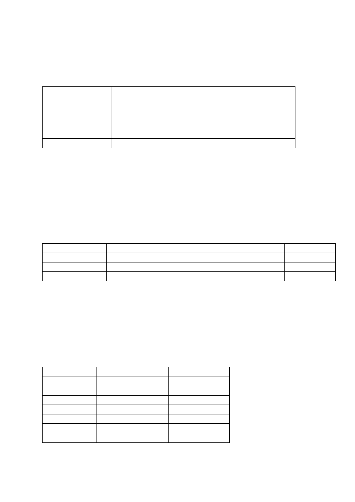
1.1 Agency Compliance Information
Table 1 Agency Compliance Standards
Product Safety Emissions Immunity NEBS Level 3
UL 60950
CSA 22.2 No. 60950
IEC60950
EN60950
AS/NZS 60950
FCC part 15, Class A
ETSI EN300 386
CISPR 22 Class A
VCCI Class A
EN55022, Class A
AS/NZA 3548 Class A
EN61000-4-2
EN61000-4-3
EN61000-4-4
EN61000-4-5
EN61000-4-6
ETSI EN300 386
GR-63-CORE
GR-1089-CORE
Caution!
Risk of equipment damage. The intrabuilding ports of the line cards are suitable
for connection to intrabuilding or unexposed wiring or cabling only. These ports
must not be metallically connected to interfaces that connect to the outside
plant (OSP) or its wiring. These interfaces are designed for use in intrabuilding
interfaces only (Type 2 or Type 4 ports as described in GR-1089-CORE, Issue
4) and require isolation from the exposed OSP cabling. The addition of primary
protectors is not sufficient protection to connect these interfaces metallically to
OSP wiring.
Note: The SmartEdge 600 router is suitable for installation in Network
Telecommunications Facilities and as part of the Common Bonding
Network (CBN).
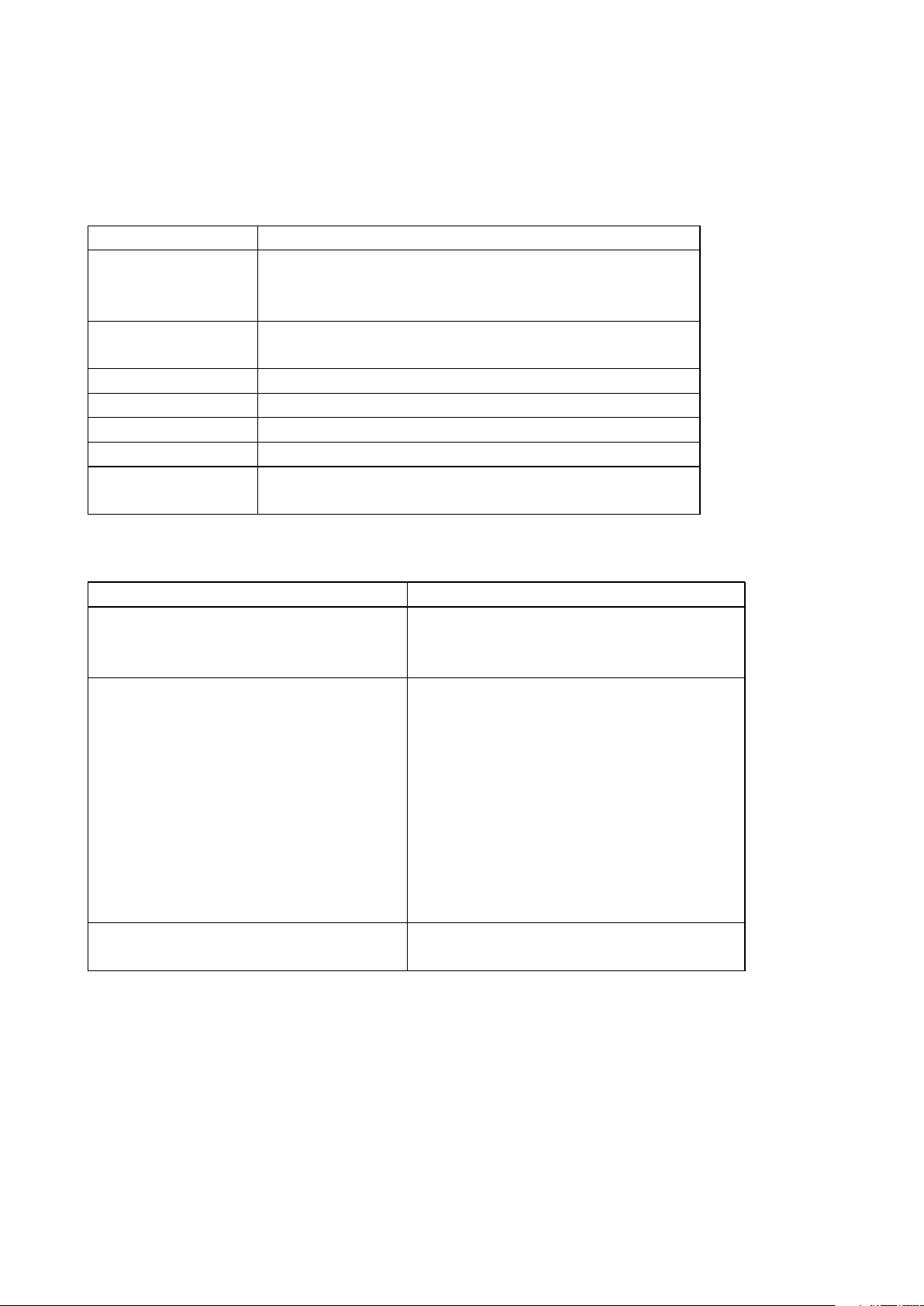
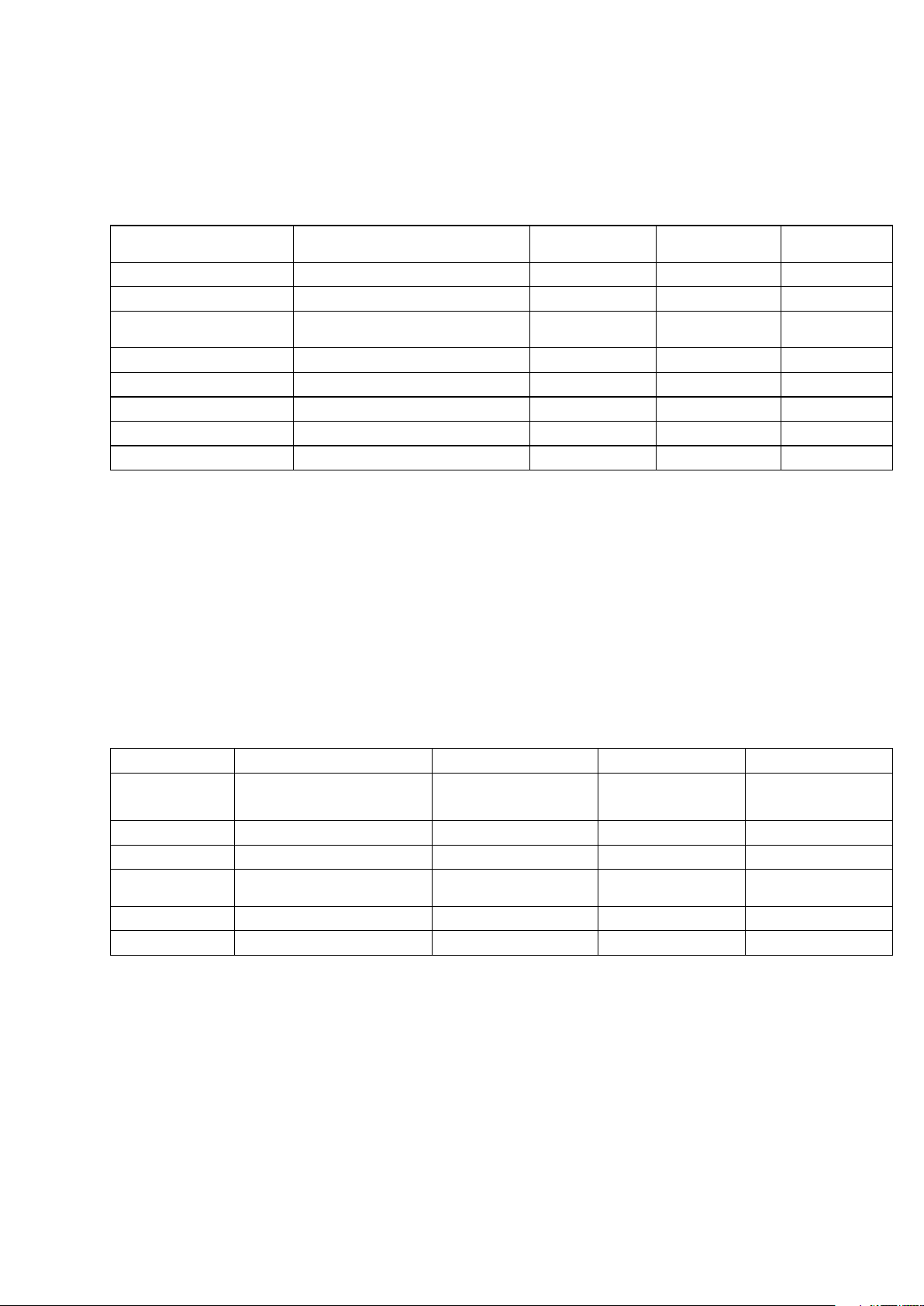
1.2 Electrical Specifications
Table 2 DC Electrical Specifications
Requirement Value
Input voltage, nominal –48.0 VDC
Input voltage range –40.0 VDC to –57.5 VDC
127/153 30-CRA 119 1170/1 Uen A | 2010-04-09
Page 8
SmartEdge 600 Router Hardware Guide
Table 2 DC Electrical Specifications
Requirement Value
Total input power, maximum 2736 VA
Input current rating per feed 57 ADC@–48 VDC
Source DC power requirement Sufficient to supply the rated input current Local codes apply
Number of input feeds Two: One from battery plant A and one from battery plant B
Table 3 AC (Optional) Electrical Specifications
Requirement Value
Input voltage, nominal 200 to 240 VAC
Input voltage range 175 VAC to 275 VAC
Input power, maximum 3120 VA
Input current rating 15.6A maximum @ 200 to 240 VAC
Input line frequency, nominal 50 to 60 Hz
Input line frequency, range 47 to 63 Hz
Source AC power requirement 20A, IEC-320
Number of input feeds Two independent branch circuits
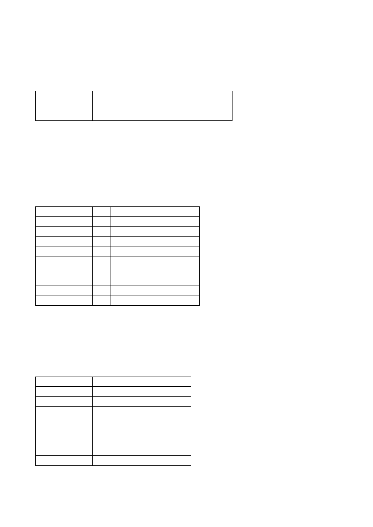
Table 4 Operating and Inrush Current for Line Cards at –48 VDC
Component Operating Current Inrush Current
ATM OC-3c/STM-1c (8-port)
ATM OC-3c/STM-1c (4-port)
Enhanced ATM OC-12c/STM-4c IR (1-port)
2.98
1.88
1.80
0.55
4.96
4.98
(1)
2 27/153 30-CRA 119 1170/1 Uen A | 2010-04-09
Page 9
Site Preparation
Table 4 Operating and Inrush Current for Line Cards at –48 VDC
Component Operating Current Inrush Current
POS OC-3c/STM-1c (8-port, any SFP version)
POS OC-12c/STM-4c (4-port, any SFP version)
POS OC-48c/STM-16c (4-port, any SFP version)
OC-192c/STM-64c (1-port, any XFP version)
10/100 Ethernet (12-port)
Fast Ethernet–Gigabit Ethernet (60-port FE, 2-port GE)
Gigabit Ethernet (4-port, first versions)
Advanced Gigabit Ethernet (4-port, second versions)
Gigabit Ethernet 3 (4-port)
Gigabit Ethernet 1020 (10-port)
Gigabit Ethernet 1020 (20-port)
Gigabit Ethernet (5-port)
Gigabit Ethernet (20-port)
10 Gigabit Ethernet (1-port)
10 Gigabit Ethernet (4-port)
(2)
(3)
2.10
2.16
3.25
2.72
1.44
2.80
1.56
1.56
2.24
2.95
3.70
2.30
6.25
2.72
6.25
1.10
1.10
1.10
10.52 (max duration is 28 ms)
4.20
0.62 (max duration is 28 ms)
4.04
4.04
4.00 (max duration is 20 µs)
14.20 (max duration is 20 µs)
12.40 (max duration is 20 µs)
1.34 (max duration is 20 µs)
1.50
10.52 (max duration is 20 µs)
1.00
(1) Inrush current occurs during power on or during the installation of a component in a powered-on chassis. Unless
noted, maximum duration is 4 ms.
(2) The 20-port GE1020 card requires two adjacent slots.
(3) Because the TX SFP is larger than a standard SFP, you cannot insert two TX SFPs side by side on the 20-port
GE line card.
(1)
Note: The conventions of "traffic card" and "line card" have been used
interchangeably in various SmartEdge documentation.
Inrush current occurs during power on or during the installation of a component
in a powered-on chassis. Unless noted, maximum duration is 4 ms.
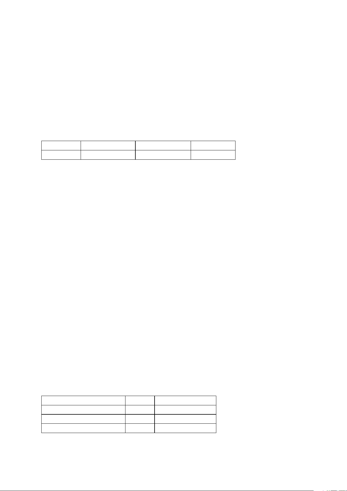
Table 5 Operating and Inrush Current for Chassis Components at –48 VDC
Component Operating Current Inrush Current
Controllers
XCRP4 (active or standby)
ASE
Advanced Services Engine
SSE
SmartEdge Storage Engine
Chassis
Fan tray (nominal speed)
Fan tray (high speed)
2.21
2.68
2.8
2.20
5.40
0.52 for 25 ms
1.20 for 120 ms
0.86 for 48 ms
6.60 for 3 ms
6.60 for 3 ms
327/153 30-CRA 119 1170/1 Uen A | 2010-04-09
Page 10

SmartEdge 600 Router Hardware Guide
1.3 Electrical Power Connections
The SmartEdge 600 chassis power architecture has connectors for a single
power zone.
Primary sources are designated as A sources; backup sources are B sources.
For a fully redundant power configuration, both sources must be connected.
Each power connection must be able to supply a minimum of 75 amperes. DC
power connections require copper wire of a size suitable for the installation in
accordance with the National Electrical Code (in the United States) or applicable
local jurisdiction (outside the United States) installation requirements. An
external fuse panel, either a stand-alone unit or incorporated in a DC power
supply system, or a circuit breaker panel is required for power-on and power-off
control. A DC-powered system uses –48 VDC power and is powered from a
fuse panel, which can be damaged by overloaded circuits.
Caution!
Risk of equipment damage. Ensure that the fuses in the external fuse panel
are suitably rated for the installation in accordance with the National Electrical
Code (in the United States) or applicable local jurisdiction (outside the United
States) installation requirements.
1.3.1 AC Power Option
You can supply power to the SmartEdge 600 by means of an optional AC
Power Shelf (BMK 907 058/1). It requires a 200-240VAC power source. It has
two power modules (BMK 905 76/1) and a split power bus for redundancy.
Each power module is capable of delivering 2725 Watts.
The AC Power Shelf has a status port for use in monitoring warnings and errors.
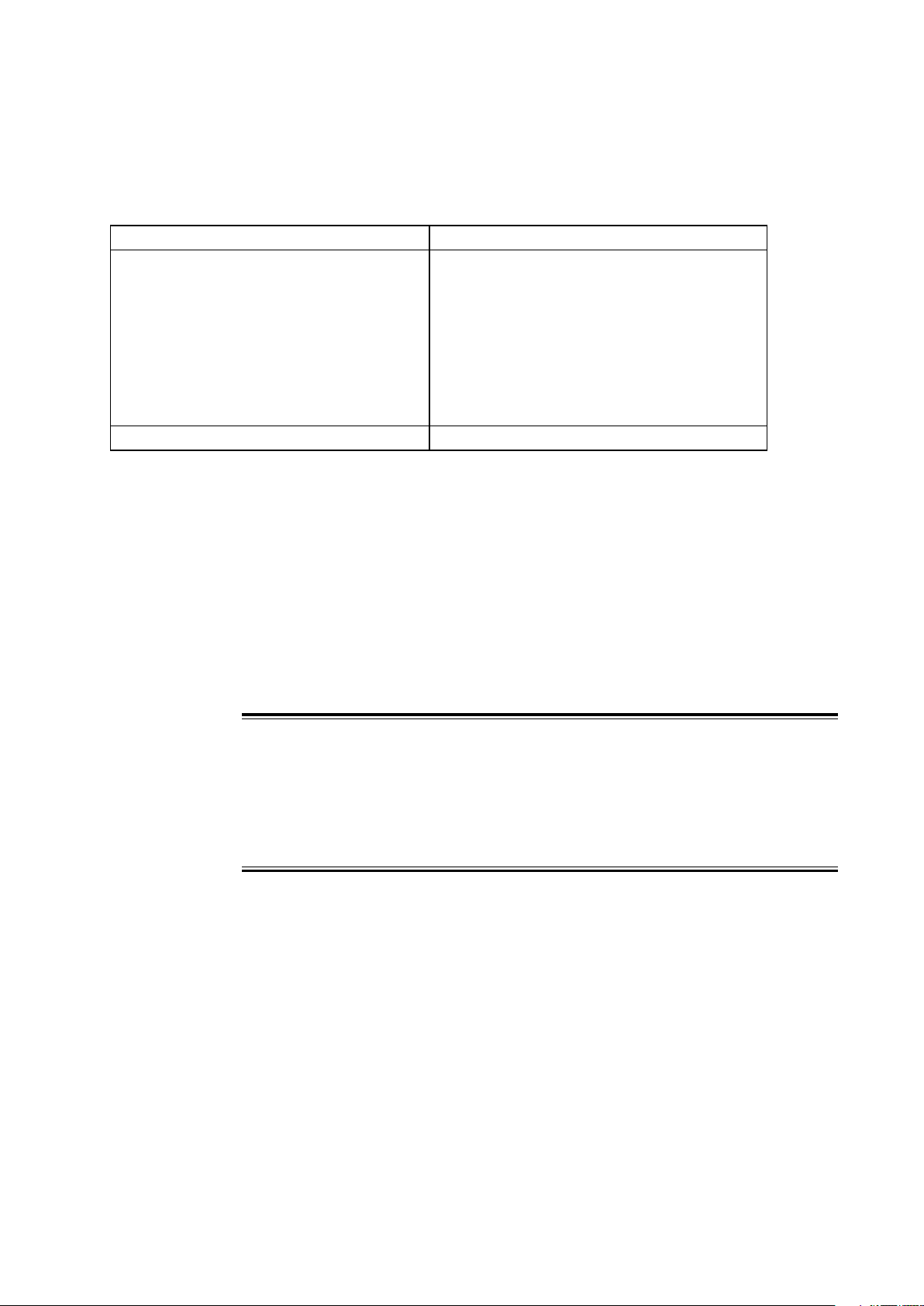
1.4 Environmental Requirements
The installation area for the SmartEdge 600 hardware must allow the following
clearances:
• A minimum of 6.0 inches (15.2 cm) at the back of the chassis (for cable
routing)
• A minimum of 20.0 inches (50.8 cm) at the front of the chassis (for
maintenance)
4
27/153 30-CRA 119 1170/1 Uen A | 2010-04-09
Page 11
Site Preparation
Caution!
Risk of equipment damage. The SmartEdge 600 router can be damaged by
lack of proper cooling and ventilation. To reduce the risk, never install the
chassis in an unventilated area, and always ensure that cooling equipment
sufficient to maintain a temperature of less than 104
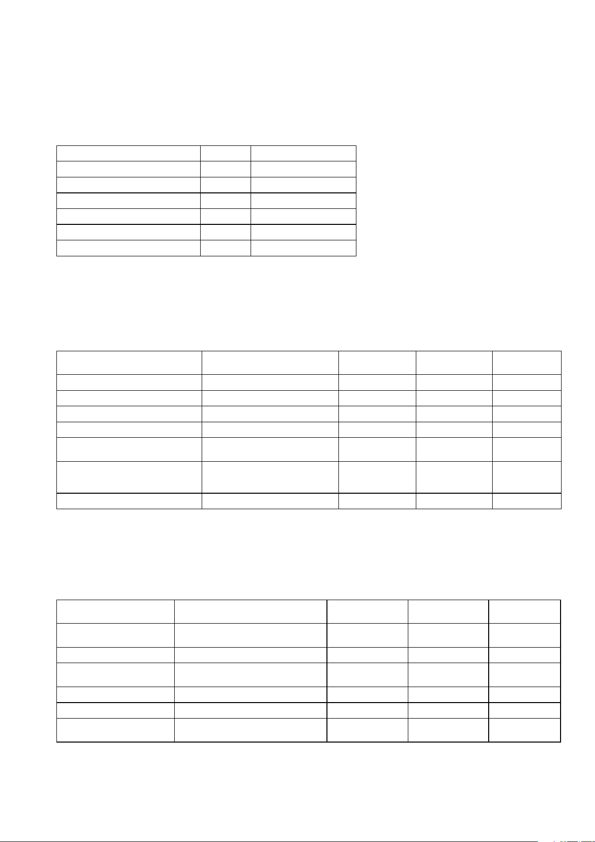
Table 6 Environmental Requirements
Specification Value
Cooling Forced air (fan cooled)
Operating temperature, nominal
Operating temperature, short term
Storage temperature
Operating relative humidity 5 to 95% RH (noncondensing)
Storage relative humidity 5 to 95% RH (noncondensing)
Operating altitude 0 to 10,000 ft (3,048m)
Earthquake Telcordia 63-CORE Zone 4-compliant
Thermal dissipation, maximum 2,736 watts (9,336 BTU/hour)
(1)
to 104
41
23
to 131F (–5
-38
to 150
(1) Short term refers to a period of time not more than 96 consecutive hours and a total of not more than 15 days in
one year (360 hours in any given year, but no more than 15 occurrences during that year).
F(5
to 40C)
to 55
F (–40to 70
C)
C)
F (40C) is available.
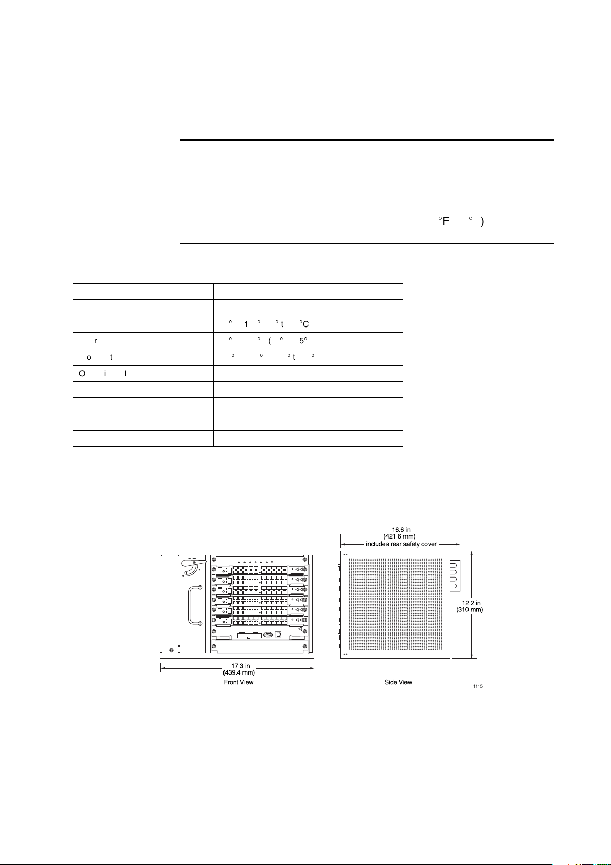
1.5 Physical Specifications
Figure 1 SmartEdge 600 Chassis Dimensions
Chassis depth dimension includes the front cable tray and the power safety
cover.
27/153 30-CRA 119 1170/1 Uen A | 2010-04-09
5
Page 12
SmartEdge 600 Router Hardware Guide
Table 7 SmartEdge 600 Chassis Physical Specifications
Mechanical Specification Value
SmartEdge 600 chassis
dimensions
Chassis weight 48.7 lb (22.1 kg) all card slots empty, ready for installation
Chassis mounting 19- or 23-inch rack
Total slots
Line card slots
Common equipment slots
Card dimensions 9.75 inches (247.7 mm) height
12.2 inches (310.0 mm) height
17.3 inches (439.4 mm) width
16.6 inches (421.6 mm) depth
94 lb (42.6 kg) with all slots filled
8
6
2
12.73 inches (323.3 mm) depth
(1)
(1) Includes rear safety cover.
Table 8 SmartEdge 600 Connections
Card Connections Connector Type
ATM OC-12c/STM-4c IR (1-port)
ATM OC-3c/STM-1c (4-port)
ATM OC-3c/STM-1c (8-port)
10/100 Ethernet (12-port)
Fast Ethernet–Gigabit Ethernet (60-port FE, 2-port GE)
Gigabit Ethernet (4-port, first and second versions)
Gigabit Ethernet 3 (4-port)
Gigabit Ethernet 1020 (10-port)
Gigabit Ethernet 1020 (20-port)
Gigabit Ethernet (5-port)
Gigabit Ethernet (20-port)
10 Gigabit Ethernet (1-port)
10 Gigabit Ethernet (4-port)
OC-192c/STM-64c (any XFP version)
OC-48c/STM-16c (4-port, any SFP version)
(1)
LC, front chassis access
LC, front chassis access
LC, front chassis access
RJ-45, front chassis access
MRJ21 (FE ports), RJ-45 (GE ports), front chassis
(2)
access
SC or RJ-45, front chassis access
LC, front chassis access
LC, front chassis access
LC, front chassis access
LC, front chassis access
LC, front chassis access
LC, front chassis access
LC, front chassis access
LC, front chassis access
LC, front chassis access
(3)
6 27/153 30-CRA 119 1170/1 Uen A | 2010-04-09
Page 13
Site Preparation
Table 8 SmartEdge 600 Connections
Card Connections Connector Type
Management workstation (LAN)
Craft console (RS-232)
External Timing, Primary and Secondary (DS-1 or E1)
Modem, SL7 and SL8 (RS-232)
(4)
Alarm
Status/Ctl
Power and chassis ground
Advanced Services Engine RJ-45, front chassis access
(1) The 20-port GE1020 card requires two adjacent slots.
(2) The front panel has five MRJ21 connectors, each supporting 12 FE ports; a breakout cable, which uses RJ-45
connectors for the individual ports, is available from Ericsson.
(3) Connector type is determined by the gigabit interface converter (GBIC) version installed in the port.
(4) The SmartEdge OS does not support this connection.
(4)
(4)
RJ-45, front chassis access
DB-9, front chassis access
DB-9, rear chassis access
DB-25, rear chassis access
DB-25, rear chassis access
DB-37, rear chassis access
1/4-20 threaded holes on 0.625-inch (1.59 cm) centers,
rear chassis access
1.6 Select the Rack
You can mount the SmartEdge 600 chassis in a standard 19- or 23-inch rack.
Brackets for the 23-inch rack are not shipped with the chassis but are available
in the bracket spares kit (NTM 101 1517/1).
Risk of equipment damage. Never install the chassis in a rack that has not
been stabilized by being bolted to the floor and to the ceiling and always select
a mounting position that is suitable to the type of rack in which the chassis
is being installed.
The SmartEdge 600 chassis requires 7 RUs—1.75 inches (4.50 cm). The
optional AC shelf at the bottom of the rack requires 1 RU; a stand-alone
external fuse panel requires 1 RU.
Note: Ericsson does not supply fuse panels.
Caution!
27/153 30-CRA 119 1170/1 Uen A | 2010-04-09
7
Page 14
SmartEdge 600 Router Hardware Guide
Figure 2 SmartEdge 600 Chassis in 42-RU Rack
Regardless of rack width and height, the SmartEdge 600 chassis can be
mounted only in the flush position.
1.7 Select the Installation Method
The SmartEdge 600 chassis is heavy, as much as 48.7 lb (22.1 kg) when
all slots have cards installed, and somewhat unwieldy. When planning the
installation, consideration must be given to how the chassis can best be
installed at the site you have chosen.
Two possible installation scenarios are to:
• Install the chassis as shipped.
Two people can perform the installation without additional aid if the chassis
is empty with no removable components installed. The effective weight of
the chassis without removable components is 48.7 lb (22.1 kg).
• Install the chassis with all components already installed.
Use a power lifting device to position the chassis in the rack if you intend to
install the fan tray, cable tray, and controller and line cards before installing
the system in a rack.
8
27/153 30-CRA 119 1170/1 Uen A | 2010-04-09
Page 15

1.8 Equipment and Personal Safety Warnings
Warning!
Risk of electrical shock. Always remove the fuses in the fuse panel for all power
sources to the chassis before connecting the power cables to the chassis. After
the power cables are connected to the chassis and the fuse panel, the system
is fully powered on; there is no power switch.
Warning!
Site Preparation
Risk of electrical shock. This equipment must be connected to a protective
ground in accordance with the instructions provided in this guide. Improper
grounding can result in an electrical shock.
Warning!
Risk of electrical shock. Only qualified personnel are allowed to service the
system. There are mechanical and electrical shock hazards present throughout
the system if one or more of the cards is removed.
Caution!
Risk of severe damage to your eyes. Do not stare into the connector or directly
view the laser beam emerging from the connector. Keep the connectors
covered until you are ready to connect the fiber-optic cables. All versions of
the optical cards are Class 1 products, which use lasers to convert electrical
signals to optical signals that can damage your eyes.
927/153 30-CRA 119 1170/1 Uen A | 2010-04-09
Page 16

SmartEdge 600 Router Hardware Guide
Warning!
Risk of personal injury. Disconnect the telecommunications network cables
before removing the card to which they are connected. This equipment does
not provide safety isolation between any port that is connected to a digital
network termination point and any other port to which terminal equipment may
be connected.
1.9 DC Power Source Warnings
Warning!
Risk of electrical shock. A readily accessible disconnection device, such as a
fuse in a fuse panel, must be provided in the fixed wiring for each DC power
source. It must be suitable for the rated voltage and current specified. Because
a system is fully powered on after all power connections are made, it can cause
shock if a power cable is disconnected from the chassis.
Warning!
Risk of electrical shock. Disconnect all telecommunications network lines
before disconnecting the unit from the ground point. Safe operation of this
equipment requires connection to a ground point.
Warning!
Risk of electrical shock. DC power sources can cause severe injury. The DC
power sources must be installed only in restricted access areas (dedicated
equipment rooms, equipment closets, or the like) in accordance with Articles
110-17, 110-26, and 110-27 of the National Electric Code, ANSI/NFPA 70.
Connect the chassis to a –48 VDC source that is reliably connected to earth.
10 27/153 30-CRA 119 1170/1 Uen A | 2010-04-09
Page 17

Site Preparation
1.10 Access During Initial Startup and Reload Operations
During the initial startup, only the operable console port is the one labeled
ENET MGMT on the XCRP4 Controller card. During a reload operation, the
management port is disabled until the initial stage of the reload is complete; all
messages displayed during the reload are sent to the console port.
You access the SmartEdge 600 router with a terminal connected to the console
port, either directly or through a terminal server.
For information about configuring cards, ports, and circuits, see configuration
documents located at h
ttps://ebusiness.ericsson.net.
1.11 Access During Normal Operations
After you have configured the management port, you can use one or more of
the following options to provide management access:
• A local management workstation, using a connection to the Ethernet
management port on a controller card
• A remote management workstation, using a routed or bridged connection
to the Ethernet management port on a controller card
• A local console terminal with a direct connection to the Craft port on a
controller card
• A remote console terminal with a connection to the Craft port on a controller
card, using a terminal server or a modem
For redundancy, we recommend using two different methods (for example,
a remote workstation and a remote console terminal with a connection to
a terminal server). Further, if the configuration of the SmartEdge 600 router
includes redundant controller cards, you should use the same means of access
to connect each controller card, so that consistent management access, despite
a failure, is guaranteed.
1.12 Management Access Options
Table 9 Options for Management Access
Option Equipment Requirements
Ethernet port connection to a local
management workstation
Ethernet port connection to a
remote management workstation
A PC or workstation with support for SSH and Telnet. Shielded Ethernet crossover cable.
A PC or workstation with support for SSH and Telnet. Shielded Ethernet straight cable (shipped
with the system). Router or bridge.
1127/153 30-CRA 119 1170/1 Uen A | 2010-04-09
Page 18
SmartEdge 600 Router Hardware Guide
Table 9 Options for Management Access
Option Equipment Requirements
Craft 2 port connection to a local
console terminal
Craft 2 port connection to a
remote console terminal
Local terminal—choose one of the following options:
• ASCII/VT100 console terminal or equivalent that runs at 9600 bits per second, 8 data bits, no
parity, 1 stop bit.
• PC or workstation in the same configuration as the ASCII/VT100 terminal.
Terminal server.
Craft console cable (shipped with the system).
Local terminal—choose one of the following options:
• ASCII/VT100 console terminal or equivalent that runs at 9600 bits per second, 8 data bits, no
parity, 1 stop bit.
• PC or workstation in the same configuration as the ASCII/VT100 terminal.
A modem that runs at 56 kbps (maximum), 8 data bits, no parity, 1 stop bit, or terminal server.
Modem or terminal server cable.
1.13 Gathering Cables and Tools
You need cables for the following connections:
• Line card cables:
0
Ethernet cards
0
Gigabit Ethernet cards
• Operations cables:
0
Console terminal and management workstation (RS-232, LAN)
0
External timing (one or two, optional)
• Power cables:
0
DC power (four or eight)
0
Chassis ground (two)
If you intend to build your own cables, see Management Access Cables for
cable and connector specifications.
Table 10 Tools Needed for SmartEdge 600 Hardware Installation
Tool Purpose
Heavy-duty cart Transport chassis and system equipment from the receiving area to the installation
Power lifter Optional (depending on installation scenario). Position the chassis in the rack.
site.
12 27/153 30-CRA 119 1170/1 Uen A | 2010-04-09
Page 19
Site Preparation
Table 10 Tools Needed for SmartEdge 600 Hardware Installation
Tool Purpose
#1 Phillips screwdriver Remove and install the fan tray and cable tray; remove and install the cards. The
#2 or #3 Phillips screwdriver
7/16-inch torque wrench Connect the chassis ground cables.
Cable crimping tool
(2)
(1) Depending on the screws that you use to install the chassis in a rack, a #3 Phillips screwdriver might be more
appropriate than the #2 screwdriver.
(2) The OUR840 manufactured by Burndy Tooling (recommended) or equivalent.
(3) When barrel lugs are not provided, other options are available to secure the conductors.
screwdriver needs a 0.1875-inch barrel that is 5 to 6 inches long to install and
remove the cable tray.
(1)
Attach the mounting brackets to the chassis and air ramp. Install the chassis and air
ramp in the rack.
Secure barrel or open lugs to the DC power and chassis ground cables.
(3)
1.14 Management Access Cables
A management access cable connects a console terminal, management
workstation, or modem to a port on a controller card or the chassis.
Table 11 Cable Specifications for Management Access Cables
Name Description System Connectors Cable Connector Maximum Length
Craft console cable RS-232 DB-9 female DB-9 male 35.0ft - 10.7m
Ethernet crossover cable Category 5 shielded twisted-pair RJ-45 female RJ-45 male 328.1ft - 100.0m
Ethernet straight cable Category 5 shielded twisted-pair RJ-45 female RJ-45 male 328.1ft - 100.0
(1) The maximum cable length for RS-232 cables is for any baud rate.
1.14.1 Craft Console Cable
This cable connects a local Craft console to the Craft 2 port on a controller
card. The cable is constructed as a straight-through connection between a
DB-9 male connector at the system end and a DB-9 female connector at the
computer terminal end.
Table 12 Craft Console Cable Pin Assignments
Signal Name
DCD (input) Received Line Signal Detector Not used
TXD (output) Transmitted Data SmartEdge 600 output
RXD (input) Received Data SmartEdge 600 input
DSR (input) DCE Ready Not used
–
DTR (output) DTE Ready Not used
CTS (input) Clear to Send Not used
(1)
Signal Function Notes
Signal Ground
–
(1)
1327/153 30-CRA 119 1170/1 Uen A | 2010-04-09
Page 20
SmartEdge 600 Router Hardware Guide
Table 12 Craft Console Cable Pin Assignments
Signal Name
RTS (output) Request to Send Not used
RI (input) Ring Indicator Not used
(1) The direction, input or output, is with respect to the controller card: input describes data flowing into the controller
card; output describes data being transmitted by the controller card.
(1)
Signal Function Notes
1.14.2 Ethernet Crossover Cable
This shielded cable connects the Ethernet port on a PC to the Ethernet port
on a controller card. Both ends of the cable are terminated in standard RJ-45
eight-pin modular plugs.
Table 13 Ethernet Crossover Cable Pin Assignments
Other End
Signal Name Pin Notes
–
Tx (+)
Tx (–)
Rx (+)
––
––
Rx (–)
––
––
3
6
1
2
–
–
No connection
No connection
–
No connection
No connection
1.14.3 Ethernet Straight Cable
This shielded cable connects the Ethernet port on a controller card to a LAN
hub. Both ends of the cable are terminated in standard RJ-45 eight-pin modular
plugs.
Table 14 Ethernet Straight Cable Pin Assignments
Signal Name Notes
Tx (+)
Tx (–)
Rx (+)
–
–
Rx (–)
–
–
–
–
–
No connection
No connection
–
No connection
No connection
14 27/153 30-CRA 119 1170/1 Uen A | 2010-04-09
Page 21
1.15 External Timing Cables
An external timing cable provides a connection from an external synchronization
source, such as a building integrated timing supply (BITS) or synchronization
supply unit (SSU), to the SmartEdge 600 router. Using two cables you can
connect the SmartEdge 600 router to primary and secondary inputs on the
external equipment.
Table 15 Cable Specification for External Timing Cable
Interface Description Chassis Connectors
External Timing Shielded twisted-pair DB-9 female DB-9 male
(1) The chassis connectors are on the rear of the chassis.
A cable consists of two individually shielded, twisted-wire pairs: one pair for the
synchronization input and another pair for the synchronization output.
(1)
Cable Connector
Site Preparation
Note: The XCRP4 Controller card can receive timing data only.
The nominal impedance of the DS-1 wire pairs is 100 ohms; that of the E1
wire pairs is 120 ohms.
One end of the cable is terminated with a DB-9 male connector; the other
end of the cable is left unterminated for attachment to the wire wrap posts
of the external equipment. Both of the DB-9 connectors (PRIMARY and
SECONDARY) on the rear panel of the SmartEdge 600 router have identical
pin assignments.
Note: An adapter, available as an option, provides wire wrap pins to allow you
to attach a cable without a connector.
To bring a signal from external equipment into the SmartEdge 600 router:
• For the DS-1 interface (BITS)—Connect the DS-1 output of the external
equipment to pins 2 and 6 of the DB-9 connector on the rear panel of the
router. The polarity of the signal does not matter. The router accepts a
standard BITS source transmitting a framed-all-ones pattern at the DS-1
rate of 1.544 Mbps.
• For the E1 interface (SSU)—Connect the E1 output of the external
equipment to pins 2 and 6 of the SSU DB-9 connector on the rear panel
of the router. The polarity of the signal does not matter. The router
accepts a standard synchronization source transmitting an HDB3-encoded,
framed-all-ones pattern at the E1 rate of 2.048 Mbps.
Table 16 External Timing Cable Pin Assignments
Signal Name
Shield Bare Wire Frame ground connection
External equipment input (+) White Twisted pair with pin 6
––
(1)
Color Notes
No connection
1527/153 30-CRA 119 1170/1 Uen A | 2010-04-09
Page 22
SmartEdge 600 Router Hardware Guide
Table 16 External Timing Cable Pin Assignments
Signal Name
External equipment output (+) White Twisted pair with pin 9
Shield Bare Wire Frame ground connection
External equipment input (–) Blue Twisted pair with pin 2
––
––
External equipment output (–) Orange Twisted pair with pin 4
(1) The direction, input or output, is with respect to the controller card: input describes data flowing into the controller
card; output describes data being transmitted by the controller card.
(1)
Color Notes
No connection
No connection
1.16 Line Card Cable Specifications
Table 17 Cable Specifications for Line Cards
Card Type Description Card End Cable End
ATM OC-12c/STM-4c Single-mode fiber LC female LC male 9.3mi - 15.0km
ATM OC-3c/STM-1c SR-0 Multimode fiber LC female LC male 1.2mi - 2.0km
ATM OC-3c/STM-1c IR-1 Single-mode fiber LC female LC male 9.3mi - 15.0km
Advanced Services Engine Category 5 shielded twisted-pair RJ-45 female RJ-45 male 328.1ft - 100.0m
10/100 Ethernet Category 5 shielded twisted-pair
FE–GE: 10/100 ports Category 5 UTP braid shielded
FE–GE: 100/1000 ports Category 5 shielded twisted-pair RJ-45 female RJ-45 male 328.1ft - 100.0m
Ethernet straight or crossover
#24 AWG solid jacket, with copper
braid, tin shielded for each port
(1)
RJ-45 female RJ-45 male 328.1ft - 100.0m
MRJ21 female RJ-45 modular
plug, shielded,
male
(1) See cable options for a 10/100 Ethernet line card table to determine which cable, straight or crossover, is suitable;
the cable must be grounded at both ends.
Maximum
Distance
328.1ft - 100.0m
1.16.1 Transceiver-Based Gigabit Ethernet Line Card Cables
Table 18 Cable Specifications for Transceiver-Based Gigabit Ethernet Line Cards
Transceiver Description Card End
SX GBIC transceiver Multimode fiber 62.5/125 µm SC female SC male 1,804.4ft -
Multimode fiber 50/125 µm SC female SC male 656.2ft - 200.0m
TX transceiver 4-pair, Category 5 shielded
twisted-pair
LX GBIC transceiver Single-mode fiber 9/125 µm SC female SC male 6.2mi - 10.0km
LX70 GBIC transceiver Single-mode fiber 9/125 µm SC female SC male 43.5mi - 70.0km
SX SFP transceiver Multimode fiber 62.5/125 µm LC female LC male 1,640.4ft -
(2)
RJ-45 RJ-45 328.1ft - 100.0m
(1)
Cable End
Maximum
Distance
550.0m
500.0m
16 27/153 30-CRA 119 1170/1 Uen A | 2010-04-09
Page 23
Site Preparation
Table 18 Cable Specifications for Transceiver-Based Gigabit Ethernet Line Cards
Transceiver Description Card End
Multimode fiber 50/125 µm LC female LC male 656.2ft - 200.0m
LX SFP transceiver Single-mode fiber 9/125 µm LC female LC male 6.2mi - 10.0km
ZX SFP transceiver Single-mode fiber 9/125 µm LC female LC male 49.7mi -
SR/SW XFP transceiver Multimode fiber 50/125 µm LC female LC male 984.4ft - 300.0m
LR/LW XFP transceiver Single-mode fiber 9/125 µm LC female LC male 6.2mi - 10.0km
ER XFP transceiver Single-mode fiber 9/125 µm LC female LC male 24.9mi - 40.0km
ZR XFP transceiver
DWDM transceiver
(4) (5)
(6)
Single-mode fiber 9/125 µm LC female LC male 49.7mi - 80.0km
Single-mode fiber 9/125 µm LC female LC male 49.7mi - 80.0km
(1)
Cable End
(1) The SC connectors on the card are type SC/PC; cable and card connectors must match.
(2) To comply with GR-1089 intrabuilding lightning surge requirements, intrabuilding wiring must be shielded, and the
shield for the wiring must be grounded at both ends.
(3) When the port level lossless flow control is enabled, the distance reach is limited to 43.5 mi (70.0 km).
(4) The ZR XFP transceiver is a multi-rate device and can be used in the 10GE line card and the SONET/SDH
OC-192c/STM-64c LR line card.
(5) Use part number XFP-OC192-LR2 when ordering the XFP transceivers with 10GE ZR functionality.
(6) DWDM XFP transceivers support only ITU channels 35, 36, 37, 53, and 54; see ITU DWDM Transmit Frequencies
and Wavelengths table in Chapter 6 for the frequency and wavelength of each ITU channel; specified in ITU G.694.1.
Maximum
Distance
(3)
80.0km
1.17 Transceiver-Based SONET/SDH Line Card Cables
Table 19 Cable Specifications for the SONET/SDH Line Cards
Transceiver Type Description Card Connector
SR / MM Multimode fiber 62.5/125 µm LC female LC male 1,640.4 ft - 500.0 m
SR / SM
IR / SM
IR-2 / SM (with XFP
transceiver)
LR-1 / SM Single-mode fiber 9/125 µm LC female LC male 24.9 mi - 40.0 km
LR-2 / SM Single-mode fiber 9/125 µm LC female LC male 49.7 mi - 80.0 km
(3)
(3)
Single-mode fiber 9/125 µm LC, FC, or SC female LC, FC, or SC male 1.2 mi - 2.0 km
Single-mode fiber 9/125 µm LC female LC male 9.3 mi - 15.0 km
Single-mode fiber 9/125 µm LC female LC male 24.9 mi - 40.0 km
(1) The SC connectors on the card are type SC/PC; cable and card connectors must match.
(2) For SFP-OC12-MM transceiver, the maximum distance is 500 meters.
(3) Use part number SFP-OC3-SM-IR when ordering the SFP transceivers with POS OC-3 SR-1 or POS OC-3
IR-1 functionality.
(1)
Cable Connector Maximum Distance
1.2 mi - 2.0 km
(2)
1727/153 30-CRA 119 1170/1 Uen A | 2010-04-09
Page 24
SmartEdge 600 Router Hardware Guide
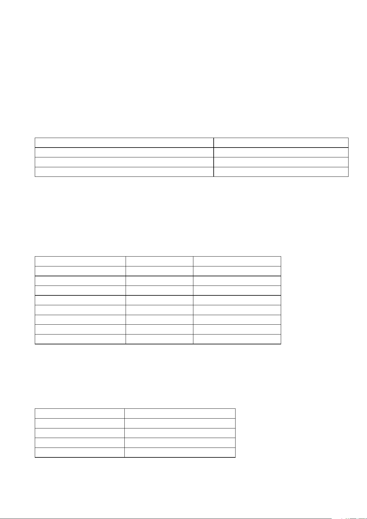
1.18 10/100 Ethernet and Fast Ethernet–Gigabit Ethernet
Cables
The choice of an Ethernet straight or crossover cable for a port on the 10/100
Ethernet card depends on the equipment to which it is being connected.
Table 20 Cable Options for a 10/100 Ethernet Line Card
Configuration Cable Type
Port is connected to a router. Straight
Port is connected to a switch. Crossover
Port is connected to a 10/100 Ethernet port in another SmartEdge router. Crossover
Note: The 10/100 Ethernet line card wiring is cross-connected like a switch or
hub; this condition is denoted with the label “X” by each port.
1.18.1 10/100 Ethernet Crossover Cable Pin Assignments
Both ends of this shielded and grounded cable are terminated in standard
RJ-45 eight-pin modular plugs.
Table 21 10/100 Ethernet Crossover Cable Pin Assignments
Signal Name Pin Notes
Rx (+)
Rx (–)
Tx (+)
––
––
Tx (–)
––
––
3
6
1
2
–
–
–
Termination network
Termination network
–
Termination network
Termination network
1.18.2 10/100 Ethernet Straight Cable Pin Assignments
Both ends of this shielded and grounded cable are terminated in standard
RJ-45 eight-pin modular plugs.
Table 22 10/100 Ethernet Straight Cable Pin Assignments
Signal Name Notes
Rx (+)
Rx (–)
Tx (+)
–
–
–
–
Termination network
18 27/153 30-CRA 119 1170/1 Uen A | 2010-04-09
Page 25

Table 22 10/100 Ethernet Straight Cable Pin Assignments
Signal Name Notes
–
Tx (–)
–
–
Termination network
–
Termination network
Termination network
1.18.3 Fast Ethernet Breakout Cable Pin Assignments
Table 23 Fast Ethernet Breakout Cable Pin Assignments
Port MRJ21 Pins RJ-45 Pins Colors
1 121314 1236
2 341516 1236
3 25263728 1236
4 27283940 1236
5
6 781920 1236
7
8 31324344 1236
9 9 10 21 22 1 2 3 6
10 11 12 23 24 1 2 3 6
11 33 34 45 46 1 2 3 6
12 35 36 47 48 1 2 3 6
561718 1236
29 30 41 42 1 2 3 6
White/Blue Blue/White White/Orange Orange/White
White/Green Green/White White/Brown Brown/White
White/Gray Gray/White Red/Blue Blue/Red
Red/Orange Orange/Red Red/Green Green/Red
Red/Brown Brown/Red Red/Gray Gray/Red
Black/Blue Blue/Black Black/Orange Orange/Black
Black/Green Green/Black Black/Brown Brown/Black
Black/Gray Gray/Black Yellow/Blue Blue/Yellow
Yellow/Orange Orange/Yellow Yellow/Green Green/Yellow
Yellow/Brown Brown/Yellow Yellow/Gray Gray/Yellow
Violet/Blue2 Blue/Violet Violet/Orange Orange/Violet
Violet/Green2 Green/Violet Violet/Brown Brown/Violet
Site Preparation
1927/153 30-CRA 119 1170/1 Uen A | 2010-04-09
Page 26

SmartEdge 600 Router Hardware Guide
20 27/153 30-CRA 119 1170/1 Uen A | 2010-04-09
Page 27
2 Installing the Hardware
Installing the Hardware
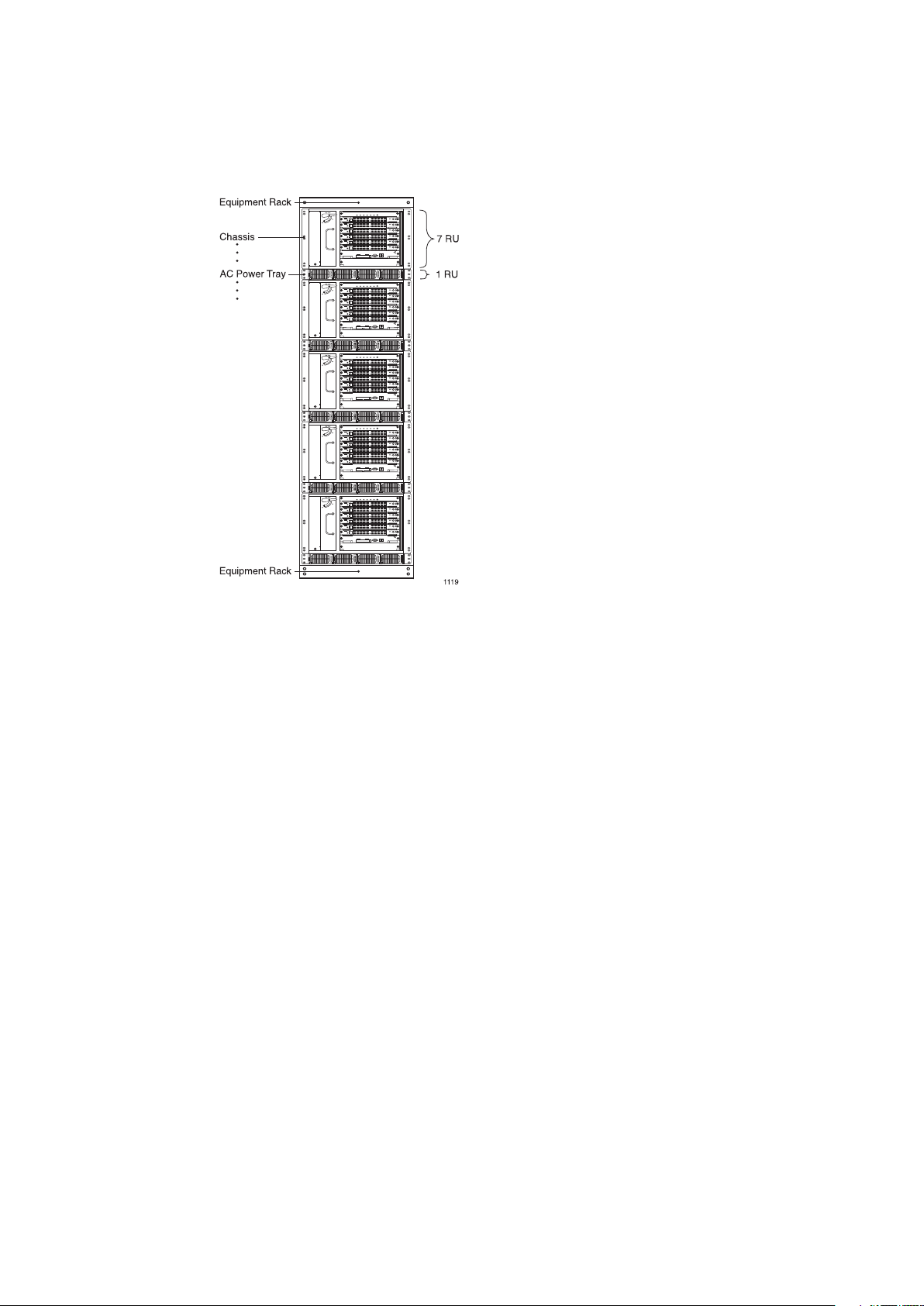
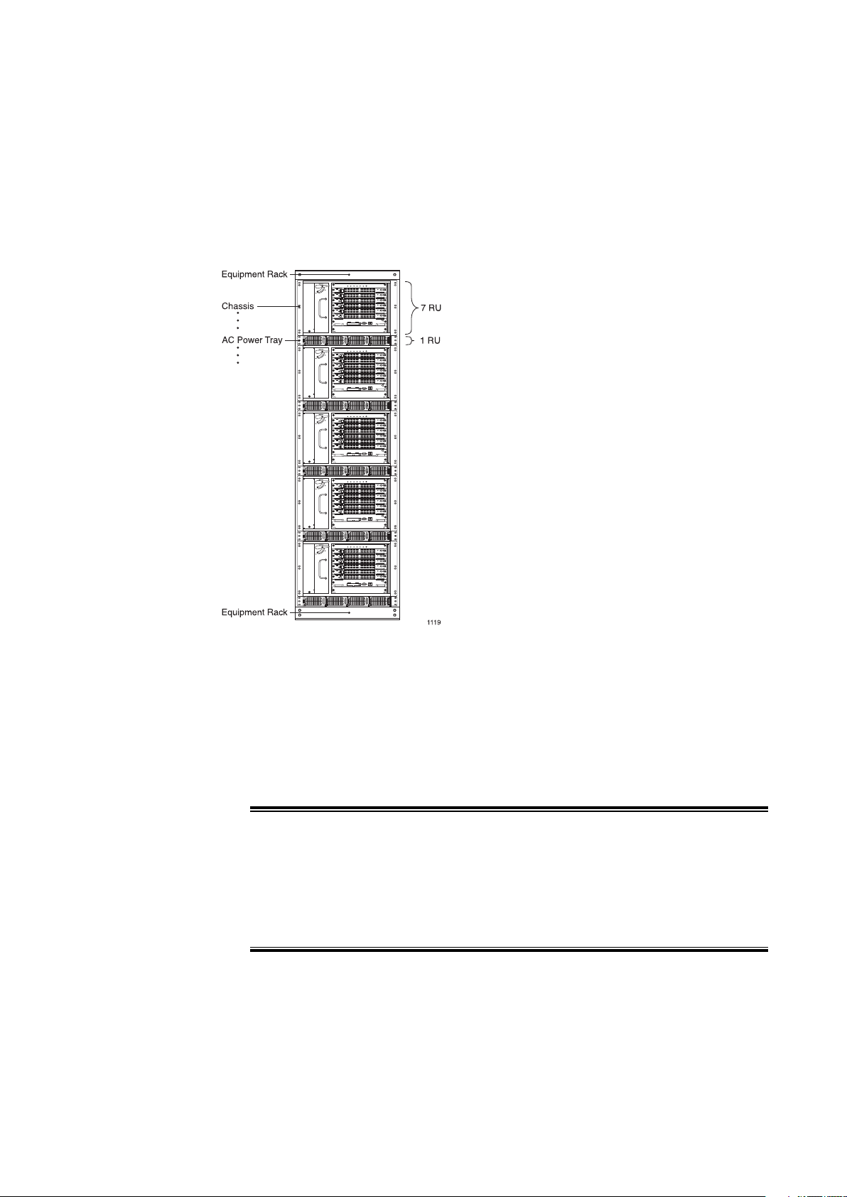
Figure 3 Fully Loaded 42 RU Rack Configuration
Decide where in the rack to position the chassis based on component stackup:
• The chassis requires seven rack units (RUs). An RU is 1.75 inches (4.5 cm).
• The optional AC power shelf requires one RU. It must be installed
immediately below the chassis.
• A standalone external fuse panel requires one RU.
Caution!
Risk of equipment damage. Never install the chassis in a rack that has not
been stabilized by being bolted to the floor and to the ceiling and always
select a mounting position that is suitable to the type of rack in which the
chassis is being installed.
2127/153 30-CRA 119 1170/1 Uen A | 2010-04-09
Page 28
SmartEdge 600 Router Hardware Guide
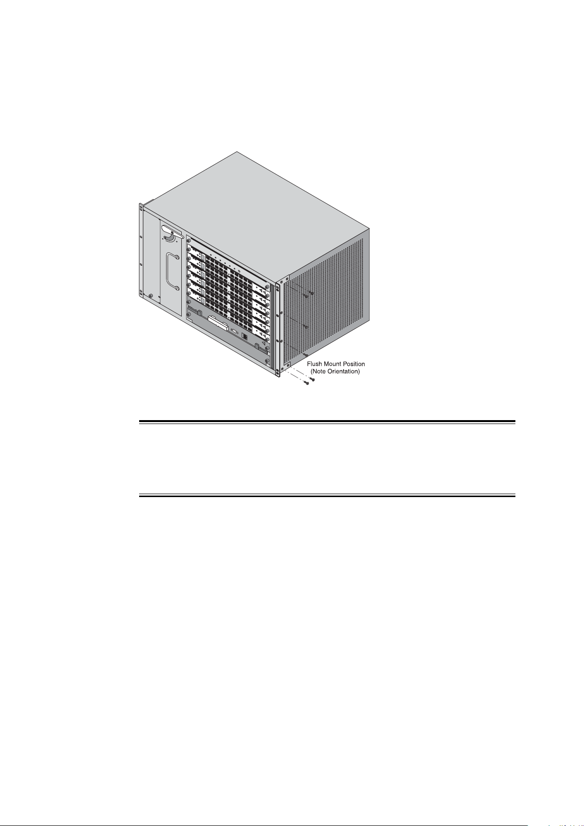
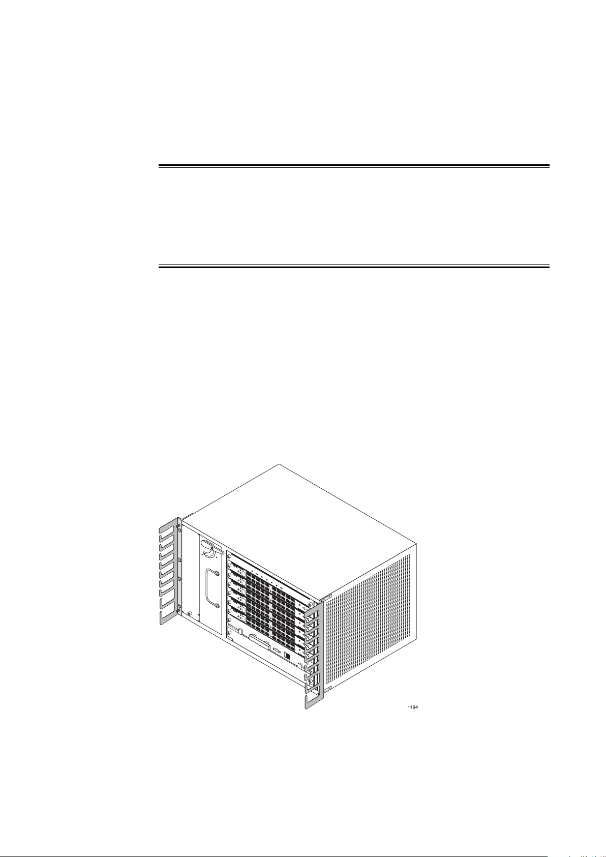
2.1 Install the Chassis Mounting Brackets
FAN TRAY
114 9
Figure 4 Installing Chassis Brackets for Flush Mount Position
Caution!
Risk of equipment damage. Always use the number and type of screws
specified in the instructions.
To install brackets:
1. Position a mounting bracket against one side of the chassis, lining up the
screw holes in the bracket with the screw holes in the side of the chassis.
2. Using a Phillips screwdriver, attach the bracket to the chassis with the
screws provided with the mounting bracket; tighten to a maximum torque of
15.0 inch-lbs (1.7 Newton-meters).
3. Repeat steps 1 and 2 to attach the second bracket to the other side of
the chassis.
22
27/153 30-CRA 119 1170/1 Uen A | 2010-04-09
Page 29
2.2 Install the Chassis
Risk of personal injury. Do not lift or move the chassis without the aid of another
trained person A fully loaded chassis can weigh as much as 94 lb (42.6 kg) and
can cause injury if one person attempts to lift or move it. Always follow the
procedures at this installation site for safely lifting heavy objects.
Install the chassis in the rack:
1. With another installation engineer, lift the chassis to the position selected
in the rack.
Installing the Hardware
Warning!
2. Line up the screw holes in the mounting brackets with the screw holes
in the rack.
3. With one engineer holding the chassis in place, use the Phillips screwdriver
to secure the shelf to the rack using fasteners of the type compatible with
the rack. Tighten the fasteners to the vendor recommended torque level.
2.3 Install the Cable Management Brackets
Figure 5 Installing the Cable Management Brackets
27/153 30-CRA 119 1170/1 Uen A | 2010-04-09
23
Page 30

SmartEdge 600 Router Hardware Guide
To install the left-side bracket, align it with the screw holes at the left side of
the rack and secure it to the rack with the two captive fasteners; tighten to a
maximum torque of 8.0 inch-lbs (0.9 Newton-meters).
For additional cable management, you can install another cable management
bracket at the right side of the chassis.
Note: When you install a ride-side cable management bracket, the air filter
access will be limited only to removal from the rear of the chassis.
2.4 Connect Power and Ground Cables
The chassis ground terminal is located at the bottom-right corner of the back
panel. The ground cables must be of a size suitable for the installation, and
must be installed in accordance with the National Electrical Code (in the
United States), or the applicable local jurisdiction (outside the United States)
installation requirements.
Connect a chassis ground cable:
1. Using a crimping tool, attach a two-hole lug to one end of the ground cable.
2. Secure the connection with a pair of lug nuts; tighten to a maximum torque
of 15.0 inch-lbs (1.7 Newton-meters).
3. Connect the other end of the cable to an appropriate ground point.
2.4.1 Connect DC Power Sources
The SmartEdge 600 chassis has two terminal blocks on the rear of the chassis
labeled BATTERY A and BATTERY B for A-side and B-side DC power cables,
which provides full power redundancy. Each terminal block has a pair of 1/4-20
studs.
The A- and B-side power cables connect to separate A-side and B-side
connectors on the external fuse panel or circuit breaker panel.
The terminal studs are labeled RETURN and -48V. Each power cable must
be of a size suitable for the installation and installed in accordance with the
National Electrical Code (in the United States) or applicable local jurisdiction
(outside the United States) installation requirements.
The following DC power source warnings and cautions apply when connecting
DC power sources:
24
27/153 30-CRA 119 1170/1 Uen A | 2010-04-09
Page 31

Installing the Hardware
Warning!
Risk of electrical shock. The DC power sources must be installed only in
restricted access areas (dedicated equipment rooms, equipment closets, or the
like) in accordance with Articles 110-17, 110-26, and 110-27 of the National
Electric Code, ANSI/NFPA 70. Connect the chassis to a –48 VDC source that
is reliably connected to earth.
Warning!
Risk of electrical shock. A readily accessible disconnect device, such as a fuse
in a fuse panel, must be provided in the fixed wiring for each DC power source.
It must be suitable for the rated voltage and current specified. The system is
fully powered on after all power connections are made, it can cause shock if a
power cable is disconnected from the chassis.
Warning!
Risk of electrical shock. Disconnect all telecommunications network lines
before disconnecting the unit from the ground point. Safe operation of this
equipment requires connection to a ground point.
Warning!
Risk of electrical shock. This equipment uses –48 VDC power, which can
cause shock if inadequate power sources are connected to it. Verify that the
power sources for the system and DC power cables meet the specifications
provided in Chapter 1.
2527/153 30-CRA 119 1170/1 Uen A | 2010-04-09
Page 32

SmartEdge 600 Router Hardware Guide
Risk of electrical shock. Always remove the fuses for both the A-side and
B-side power sources in the fuse panel before connecting the power cables to
the chassis. After the power cables are connected to the chassis and the fuse
panel, the system is fully powered on; there is no power switch.
Risk of electrical shock. This equipment must be connected to a protective
ground in accordance with the instructions provided in this guide. Improper
grounding can result in an electrical shock.
Warning!
Warning!
Caution!
Risk of equipment damage. A DC-powered system uses –48 VDC power, is
powered from a fuse panel, and can be damaged by overloaded circuits. To
reduce the risk, ensure that the fuses in the external fuse panel are suitably
rated for the installation in accordance with the National Electrical Code (in
the United States) or applicable local jurisdiction (outside the United States)
installation requirements.
Caution!
Risk of equipment damage. You can permanently damage the chassis if you
attempt to apply DC power to it and the DC power plugs are not installed in the
connectors on the rear of the chassis. To reduce the risk, ensure that the plugs
are installed as described in the following procedure.
26 27/153 30-CRA 119 1170/1 Uen A | 2010-04-09
Page 33

2.4.1.1 Connect Power Cables
Figure 6 DC Power Connections
Installing the Hardware
Connect the power cables:
1. Using a crimping tool, attach a two-hole lug to one end of each power cable.
2. For the BATTERY A connection, secure the connection of the red cable to
RETURN with a pair of lug nuts and the black cable to -48V; tighten to a
maximum torque of 15.0 inch-lbs (1.7 Newton-meters).
3. For the BATTERY B connection, secure the connection of the red cable to
RETURN with a pair of lug nuts and the black cable to -48V; tighten to a
maximum torque of 15.0 inch-lbs (1.7 Newton-meters).
4. Use the provided metal loops in the chassis to dress the cables with tie
wraps.
5.
Note: The dressing of the DC jumper cables must allow for servicing the
push-through air filter and the fan tray from the rear of the chassis.
6. Install the safety cover.
2.5 Optional AC Power Shelf
The optional AC power shelf provides slots for two AC power modules, which
allows a SmartEdge 600 router to be installed at a site for which DC power
sources are not available. AC power shelf connects to the SmartEdge 600
chassis with two pairs of DC jumper cables using connectors on the rear of the
AC power shelf.
27/153 30-CRA 119 1170/1 Uen A | 2010-04-09
27
Page 34

SmartEdge 600 Router Hardware Guide
Warning!
Risk of personal injury. Do not attempt to access any component inside the AC
power shelf; there are no user-serviceable components inside it.
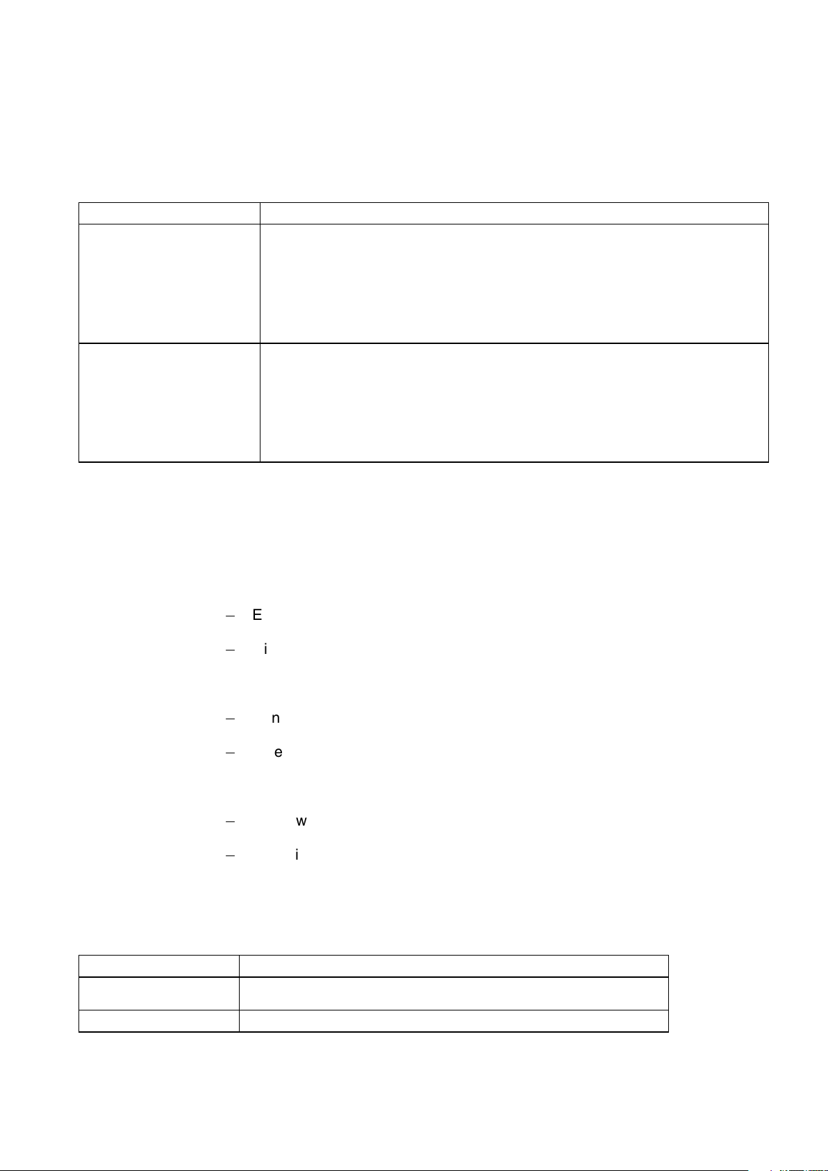
Table 24 Order Numbers
BMG907058/1 Four-slot, one rack unit (RU) AC power shelf
BMK90576/1 2725 Watt AC power module unit with AC power cord
NTM1011728/1 Spare cable kit—Includes one interconnect data cable, one set of DC jumper
cables, and two AC power cords with North American plugs.
Risk of electrical shock. Do not disconnect the power cables to the chassis
until you have first deenergized the DC power supplies, and then removed the
fuses for both the A- and B-side power sources in the fuse panel. With the
power cables connected to the chassis and the fuse panel, the system is fully
powered on, and you can incur electrical shock when you remove the cables
from the chassis connectors.
2.5.1 Install the AC Power Shelf
Warning!
28
Figure 7 Positioning an AC Power Shelf
Install the AC power shelf:
27/153 30-CRA 119 1170/1 Uen A | 2010-04-09
Page 35

1. Position the shelf directly below the chassis so the screw holes in the
shelf mounting brackets align with the screw holes in the rack just below
the chassis.
2. On a 19" wide rack, use the Phillips screwdriver to secure the shelf to the
rack using the fasteners of the type compatible with the rack. Tighten the
fasteners to the vendor recommended torque level.
2.5.1.1 Install the Ground Bracket
Installing the Hardware
Figure 8 Ground Bracket
Install the ground bracket between the shelf and the chassis:
1. On the chassis, remove the chassis ground lug at the lower-center rear of
the chassis.
2. Stack the ground bracket under the chassis ground lug and reattach it
using the existing hardware; tighten to a maximum torque of 15.0 inch-lbs
(1.7 Newton-meters).
3. On the AC power shelf, use the Phillips screwdriver to secure the bracket
to the available mounting position using the hardware provided.
2.5.1.2 Install AC Power Modules
Figure 9 AC Power Modules
27/153 30-CRA 119 1170/1 Uen A | 2010-04-09
29
Page 36

SmartEdge 600 Router Hardware Guide
Install AC power modules in the shelf:
1. Open the front ejector (fan cover) of the power module by squeezing the
latch spring and pulling open the ejector.
2. Insert a module into one of the two center slots (2 and 3) in the shelf.
Note: AC power modules operate only from the two center slots of the
3. Push the module in until the right side of the ejector engages the receptacle
slot in the shelf wall.
4. Push closed the ejector lever until the module spring latch locks on the
ejector to seat the module.
5. Insert the second module into the other center slot and repeat steps 3 and 4.
AC power shelf.
2.5.1.3 Connect the AC Power Shelf to the Chassis
Figure 10 AC Power Connections
Warning!
30
Do not connect the AC power cords to the building outlets until you have
completed the installation. If you connect the other end of the AC power cord to
a building outlet, you power on the system; there is no ON/OFF switch on the
AC power shelf.
Connect the shelf to the chassis:
27/153 30-CRA 119 1170/1 Uen A | 2010-04-09
Page 37

Installing the Hardware
1. Unpack the two 6AWG red and two black DC jumper cables.
2. Flip open the touch-safe lug landing cover on the left-side terminal block.
3. Attach the short pair of red and black DC jumper cables to the left-side
terminals—red cable to the top terminal (+) and black cable to the bottom
one (-).
4. Secure each connection with a pair of 1/4-20 lug nuts; tighten to a maximum
torque of 62.0 inch-lbs (7 Newton-meters).
5. Snap the cover shut.
6. Attach the remaining ends to the bottom (BATTERY B) terminal block of
the chassis—red cable to the top terminal (RETURN) and black to bottom
one (-48V).
7. Secure the connections with pairs of lock washers and lug nuts; tighten to a
maximum torque of 62.0 inch-lbs (7 Newton-meters).
8. Use the provided metal loops on the chassis to dress the cables with tie
wraps.
Note: Dress the DC jumper cables so the push-through air filter and fan
tray can be serviced from the rear of the chassis.
9. Repeat this procedure for the right-side self connections using the long
pair of DC jumper cables.
10. Install the safety cover.
11. Connect the control cable from J1 (right-side flat connector) on the shelf to
the chassis connector labeled AC STATUS/CTL.
12. Insert the AC power cords for each power module into connectors 2 and 3
on the shelf.
27/153 30-CRA 119 1170/1 Uen A | 2010-04-09
31
Page 38

SmartEdge 600 Router Hardware Guide
13. Power on the chassis by connecting the AC power cords to separate 220
VAC building outlets, each of which must be for a circuit rated at 20A with a
20A circuit breaker.
Note: The AC power cords ship with North American plugs installed. If
14. Check the status LEDs located on the alarm card at the front of the chassis
and the AC input power and DC output power LEDs on the front of each
installed power module.
you are connecting to another type of service, simply remove the
plugs and replace them with the appropriate plugs.
If you encounter problems installing the AC power shelf, contact your local
technical support representative.
2.6 Card Slots
Figure 11 SmartEdge 600 Card Slots
Table 25 Slot Assignments for SmartEdge 600 Cards
Card Slots Available
Controller
ATM OC-12c/STM-4c
ATM OC-3c/STM-1c (any version)
10/100 Ethernet
Fast Ethernet–Gigabit Ethernet
20-port Gigabit Ethernet 1020
Transceiver-based Gigabit Ethernet (any other version)
OC-192c/STM-64c (any XFP version)
(1)
7, 8
1to6
1to6
1to5
1to6
1to6
32 27/153 30-CRA 119 1170/1 Uen A | 2010-04-09
Page 39

Table 25 Slot Assignments for SmartEdge 600 Cards
Card Slots Available
Advanced Services Engine
SmartEdge Storage Engine
(1) The 20-port GE 1020 requires two adjacent slots.
1to6
1to6
2.7 Install Cards
Installing the Hardware
Figure 12 Installing Cards
Warning!
Risk of personal injury. Only qualified personnel must install and service the
system and its components. To avoid injury, do not attempt to access any
component inside the chassis.
3327/153 30-CRA 119 1170/1 Uen A | 2010-04-09
Page 40

SmartEdge 600 Router Hardware Guide
Risk of electrostatic discharge (ESD) damage. Always use an ESD wrist or
ankle strap when handling the card. Do not attach the wrist strap to a painted
surface. Avoid touching the card, components, or any connector pins.
Risk of severe damage to your eyes. All versions of the optical cards are Class
1 products, which use lasers to convert electrical signals to optical signals that
can damage your eyes. To reduce the risk when handling these optical cards,
keep the connectors covered until you are ready to connect the fiber-optic
cables. When you remove a cover, do not stare into the connector or directly
view the laser beam emerging from the connector.
Caution!
Caution!
Install cards:
1. Put on an ESD wrist strap, and attach it to an appropriate grounded surface.
Do not attach the wrist strap to a painted surface; an ESD convenience jack
is located on the front of the fan and alarm unit.
2. Select the slot for the card.
3. Remove the card from its antistatic bag. Save the bag for later use.
4. Align the card with the card guides at the right and left sides of the slot.
Caution!
Risk of equipment damage. If you feel any resistance, or hear the card
touching the components on the card installed in the adjacent slot at the
left, do not force the card into the slot. Ensure that the card is perpendicular
to the slot. If you feel any resistance, slightly lift the bottom edge of the
front panel until it can slide easily into the slot.
34
5. Position the ejector levers away from the front panel and then carefully slide
the card into the slot. The ejector levers rotate as the latching mechanisms
engage the walls of the slot and the connectors on the card are inserted
into the connectors on the backplane.
27/153 30-CRA 119 1170/1 Uen A | 2010-04-09
Page 41

6. Push on the ejector levers until they are parallel with the front panel; this
action fully seats the connectors with the backplane.
7. Secure the card in the chassis by tightening the screw at the top and
bottom of the front panel. Use a Phillips screwdriver to tighten each screw
to a maximum torque of 5.0 inch-lbs (0.6 Newton-meters).
8. Repeat steps 2 to 7 for each card to be installed.
2.7.1 Install Blank Cards
Risk of equipment damage. High temperature can damage router cards. Insert
a blank card in each empty slot.
Installing the Hardware
Caution!
When all cards have been installed, insert a blank card into every empty slot,
and tighten the captive screws at the top and bottom of the front panel.
2.7.2 Install Transceivers
Risk of severe damage to your eyes. Do not stare into the connector or directly
view the laser beam emerging from the connector. All versions of the optical
cards are Class 1 products, which use lasers to convert electrical signals to
optical signals that can damage your eyes. Keep the connectors covered until
you are ready to connect the fiber-optic cables.
Install Transceivers
Caution!
Figure 13 Installing a GBIC Transceiver
27/153 30-CRA 119 1170/1 Uen A | 2010-04-09
35
Page 42

SmartEdge 600 Router Hardware Guide
Figure 14 Installing an SFP Transceiver
Figure 15 Installing an XFP Transceiver
Gigabit Ethernet ports require a gigabit interface converter (GBIC), a small
form-factor pluggable (SFP), or a 10-Gbps SFP (XFP) transceiver in each port;
the port on an OC-192c/STM-64c card also requires an XFP transceiver.
Table 26 Transceiver Types for Line Cards
Line Card Transceiver
Gigabit Ethernet (4-port) GBIC SX, LX, LX70, TX
Advanced Gigabit Ethernet (4-port) GBIC SX, LX, LX70, TX
ATM OC-3c/STM-1c (4-port) GBIC IR
Enhanced ATM OC-12c/STM-4c (1-port) GBIC IR
ATM OC-3c/STM-1c (8-port) SFP SR-0, IR-1
POS OC-3c/STM-1c (8-port) SFP SR-0, SR-1, IR-1
POS OC-12c/STM-4c (4-port) SFP SR-1, IR-1
POS OC-48c/STM-16c (4-port) SFP SR-1, IR-1, LR-2
Gigabit Ethernet 3 (4-port) SFP SX, LX, TX, ZX, CWDMnnnn, DWDMnn
Gigabit Ethernet 1020 (10-port) SFP SX, LX, TX, ZX, CWDMnnnn, DWDMnn
(1)
Supported Versions
36 27/153 30-CRA 119 1170/1 Uen A | 2010-04-09
Page 43

Installing the Hardware
Table 26 Transceiver Types for Line Cards
Line Card Transceiver
Gigabit Ethernet 1020 (20-port)
Gigabit Ethernet (5-port) SFP SX, LX, TX, ZX, CWDMnnnn, DWDMnn
Gigabit Ethernet (20-port)
10 Gigabit Ethernet (1-port) XFP SR, LR, ER, ZR, DWDMnn
10 Gigabit Ethernet (4-port) XFP SR, LR, ER, ZR, DWDMnn
SONET/SDH OC-192c/STM-64c (1-port) XFP SR-1, IR-2, LR-2
(1) If the transceiver has not been qualified for use in the line card, the system displays a warning message.
(2) The 20-port GE 1020 card requires two adjacent slots.
(3) Because the TX SFP is larger than a standard SFP, you cannot insert two TX SFPs side by side on the 20-port GE
traffric card.
(2)
(3)
SFP SX, LX, TX, ZX, CWDMnnnn, DWDMnn
SFP SX, LX, TX, ZX, CWDMnnnn, DWDMnn
(1)
Supported Versions
Stop!
Risk of data loss. Install only the transceivers approved by Ericsson. You can
corrupt the system if you attempt to install transceivers have not been tested
with SmartEdge line cards. To reduce the risk, .
To install a transceiver of any type:
1. Put on an antistatic wrist strap and attach it to an appropriate grounded
surface. Do not attach the wrist strap to a painted surface; an ESD
convenience jack is located on the front of the fan tray.
Stop!
Risk of ESD damage. Always use an ESD wrist or ankle strap when
handling any transceiver. Avoid touching its connector pins.
2. Ensure that the latching mechanism is closed.
3. With the transceiver connectors aligned with the RX and TX labels on the
front panel of the line card (as shown in Figure 14 or Figure 15), slide the
transceiver into the opening for the port until the rear connector is seated
and the locking mechanism snaps into place.
The labels for the TX and RX connectors vary by vendor. An arrow, which
can be incised on the case, usually indicates the traffic direction.
4. Remove the dust cover if you are installing an optical transceiver.
27/153 30-CRA 119 1170/1 Uen A | 2010-04-09
37
Page 44

SmartEdge 600 Router Hardware Guide
GBIC transceivers are supported only on ports the first and second versions
of the Gigabit Ethernet line cards. SFP transceivers are supported only on
ports on GE3 and GE1020 line cards. XFP transceivers are supported only
on ports on 10GE line cards.
Note: Transceivers are are hot-swappable; you can replace any transceiver
without removing the Gigabit Ethernet card. However, you must shut
down the port before performing the replacement procedure.
Risk of data loss. You can corrupt the system if you attempt to install
transceivers (GBICs, SFP, or XFPs) that are not approved by Ericsson because
these items have not been tested with the SmartEdge router. To reduce the
risk, install only the transceivers approved by Ericsson.
Stop!
To remove a transceiver of any type:
1. Shut down all activities on the port with the transceiver you want to replace.
See related documentation at https://ebusiness.ericsson.net.
2. Put on an antistatic wrist strap and attach it to an appropriate grounded
surface. Do not attach the wrist strap to a painted surface; an ESD
convenience jack is located on the front of the fan tray.
Stop!
Risk of damage to fiber-optic cables. Never stop on a cable; never twist it
when connecting it to or disconnecting it from a line card.
3. Label and disconnect any cables attached to the transceiver you want to
replace.
Stop!
38
Risk of ESD damage. Transceivers contain electrostatic-sensitive devices.
To reduce the risk of ESD damage, always use an ESD wrist or ankle trap
when handling any transceiver. Avoid touching its connector pins.
4. Release the latching mechanism:
27/153 30-CRA 119 1170/1 Uen A | 2010-04-09
Page 45

Installing the Hardware
a If the transceiver has a wire handle, unlatch it, and rotate it 90
b If the transceiver has latching tabs, squeeze and hold the tabs.
5. Withdraw the transceiver from its port and insert a dust cover over the
optical connectors.
2.7.3 Install CF Cards
Figure 16 Installing an External Storage Device
to 180
.
Each controller card has an external slot on the front panel in which you can
install an optional Type I or Type II external storage device.
If you install an external storage device in the active controller card, the standby
controller card, if installed, must also have an external storage device installed;
however, the device types need not match. The XCRP4 controller card
supports Type I devices only.
To install an external storage device:
1. If you are installing the device in an XCRP4 controller card, open the door
that covers the CF Type 1 slot until it “snaps” open.
2. Hold the device so that its pin-hole side faces the slot in the controller
front panel.
3. Horizontally align the device as close to the bottom edge of the slot as
possible and perpendicular to it.
4. Slowly insert the device in the slot. If the device does not engage the
connectors with approximately 0.5 inches (1.27 cm) of the device outside
the slot, do not continue. Remove the device and repeat this step. Do not
force the device into its slot. Check for one of the following conditions:
Misaligned—Check the position and alignment as described in Step 3.
Upside down—Remove the device and rotate it 180
27/153 30-CRA 119 1170/1 Uen A | 2010-04-09
and try again.
39
Page 46

SmartEdge 600 Router Hardware Guide
Damaged—Remove the device and discard it. Do not use it in any other
equipment.
Damaged slot connectors—Replace the controller card.
5. If you are installing the device in a controller card, close the door.
2.8 Connections for Management Access
Connecting a console terminal or management workstation to the SmartEdge
600 router is often a two-stage process. Initially the console terminal is
connected to the Craft port (also referred to as the console port) to configure
the Ethernet port (also referred to as the management port).
Configuring the management port and modifying the configuration of the console
port is described in relevant documents at https://ebusiness.ericsson.net.
2.8.1 Management Workstation
Figure 17 Connections for a Management Workstation
A management workstation is connected to the SmartEdge 600 router using
the Ethernet port on the front of a controller card. This type of connection
provides access to the SmartEdge OS command-line interface (CLI) after you
have configured the port.
Two types of connections are supported:
40
• Local connection using a shielded Ethernet crossover cable
• Remote connection using a shielded Ethernet straight cable
Neither type of connection is suitable during a reload operation, because the
Ethernet port is disabled until the reload is complete.
27/153 30-CRA 119 1170/1 Uen A | 2010-04-09
Page 47

2.8.2 Local or Remote Console Terminal
Installing the Hardware
Figure 18 Connections for a Local or Remote Console
A local or remote console terminal is connected to the SmartEdge 600 router
using the Craft port on the front of a controller card. This type of connection
provides access to the operating system CLI, either directly or through a
terminal server.
A null modem is needed when connecting this cable to a modem; it is not
needed when connecting it to a PC or terminal server.
This port is always available; all system messages are directed to this port
during a power on or reload operation.
Note: When you first power on the system, the active controller card is in slot
6. Thereafter, the slot changes whenever a switchover occurs.
2.9 Connections for External Timing Cables
Figure 19 Connections for External Timing Cables
27/153 30-CRA 119 1170/1 Uen A | 2010-04-09
41
Page 48

SmartEdge 600 Router Hardware Guide
An external timing cable provides a connection from an external synchronization
source, such as a building integrated timing supply (BITS) or synchronization
supply unit (SSU), to your system. Each cable consists of two individually
shielded, twisted wire pairs: one pair for the synchronization input and another
pair for the synchronization output.
The controller cards can receive timing data only.
Two connections are possible: one from a primary source and one from a
secondary source. Either connection can provide timing for the entire chassis
(input), regardless of the configuration of the controller cards.
An adapter, available as an option, provides wire wrap pins to allow you to
attach a cable without a connector.
Note: The operating system does not support the status and control port.
2.10 Connections for Line Card Cables
All line card cables are connected to the front panels of the cards.
Table 27 Port Data for Line Cards
Line Card Type and Card Description Physical Ports
Enhanced ATM OC-12c/STM-4c IR (1-port)
ATM OC-3c/STM-1c (4-port)
ATM OC-3c/STM-1c (8-port)
10/100 Ethernet (12-port)
Fast Ethernet–Gigabit Ethernet (60-port FE, 2-port GE)
Gigabit Ethernet (4-port)
Advanced Gigabit Ethernet (4-port)
Gigabit Ethernet 3 (4-port)
Gigabit Ethernet 1020 (10-port)
Gigabit Ethernet 1020 (20-port)
Gigabit Ethernet (5-port)
Gigabit Ethernet (20-port)
10 Gigabit Ethernet (1-port)
10 Gigabit Ethernet (4-port)
OC-192c/STM-64c (1-port)
OC-48c/STM-16c (4-port)
(1)
(1) The 20-port GE1020 card requires two adjacent slots.
1
4
8
12
60, 2
4
4
4
10
20
5
20
1
4
1
4
Low-Density
Version
No
Yes
No
No
No
Yes
Yes
No
No
No
No
No
No
No
No
No
Low-Density
Port Numbers
–
1, 3
–
–
-
1, 3
1, 3
–
–
–
–
–
–
–
–
–
42 27/153 30-CRA 119 1170/1 Uen A | 2010-04-09
Page 49

2.11 Connect and Route Cables
Installing the Hardware
Figure 20 Cable Routing
Cable connections are made with standard cables.
Caution!
Risk of severe damage to your eyes. All versions of the optical cards are Class
1 products, which use lasers to convert electrical signals to optical signals that
can damage your eyes. Keep the connectors covered until you are ready to
connect the fiber-optic cables. When you remove a cover, do not stare into the
connector or directly view the laser beam emerging from the connector.
Caution!
Risk of damage to fiber-optic cables. These cables are fragile and are easily
damaged when bent. Never step on a cable. Never twist it when connecting it
to or disconnecting it from a line card.
4327/153 30-CRA 119 1170/1 Uen A | 2010-04-09
Page 50

SmartEdge 600 Router Hardware Guide
Connect and route the cables:
1. Put on an antistatic wrist strap, and attach it to an appropriate grounded
surface. Do not attach the wrist strap to a painted surface; an ESD
convenience jack is located in the lower right corner of the air intake panel
on the front of the chassis.
2. Connect and route the management access cables, depending on the
type of management access you have selected. To connect and route
the cables:
a Thread the system ends of the cables through the lowest opening in
the cable management bracket at the right side of the card slot.
b Insert each cable in the appropriate connector on the card.
c Tie-wrap the cables from each controller card to form a bundle, and
then tie each bundle to the rack.
3. Starting with the line card installed in slot 6, connect and route the line
card cables:
a Thread the system ends of the cables through an opening in the cable
management bracket at the right side of the card slot. Select an
opening that provides space for all cables to be connected to this card.
b Insert each cable in the appropriate connector on the card.
c Tie-wrap the cables to form a bundle, and then tie each bundle to the
rack.
4. Connect and route the breakout cables for the FE–GE line cards:
a Thread the MRJ21 connector end of a breakout cable through the cable
management bracket at the right side of the card slot.
b Attach the breakout cable to the right-most connector to be cabled on
an FE–GE line card. Position the connector so that the incised label
“KEY” on the connector is on the bottom side of the connector as you
face the chassis; see Figure 21.
Caution!
Risk of equipment damage. The cable connector is keyed to ensure
that you insert it with the correct orientation into the front panel
connector. However, it is possible to force an incorrectly positioned
cable connector into the connector on the front panel. To reduce the
risk of overriding the key, ensure that the incised “KEY” label is on the
left side of the connector.
44 27/153 30-CRA 119 1170/1 Uen A | 2010-04-09
Page 51

Installing the Hardware
c Tighten the captive screws without letting the front panel support the
weight of the cable.
Caution!
Risk of equipment damage. A breakout cable for the 60 10/100 ports
on the FE–GE line cards is made of AWG #24 wire and includes
individual cables for 12 ports; when connected to the FE–GE front
panel, the cable weight can cause the front panel to be separated from
the FE–GE printed circuit board. To reduce the risk, never allow the
front panel to support the weight of the cable; support the cable and
immediately route it before you connect another cable.
d Tie-wrap the breakout cable to the rack so that it supports the weight
of the cable.
e Continue to connect and route the breakout cables for the other MRJ21
connectors on the card.
f Connect and route the cables for the GE ports on the FE–GE card as
described in Step 3
Caution!
Risk of equipment damage. You can damage the GE port cables if
you thread them through the same opening in the cable management
bracket that contains the breakout cables. To reduce the risk, use a
different opening in the cable management bracket for the GE port
cables.
Figure 21 Connecting an FE–GE Breakout Cable
27/153 30-CRA 119 1170/1 Uen A | 2010-04-09
45
Page 52

SmartEdge 600 Router Hardware Guide
2.12 Power On and Off the System
Caution!
Risk of equipment damage. Ensure that the fuses in the external fuse panel
are suitably rated for the installation in accordance with the National Electrical
Code (in the United States) or applicable local jurisdiction (outside the United
States) installation requirements.
Power on a SmartEdge 600 router by inserting the fuses in the external fuse
panel. The power LEDs on the front of the chassis light, depending on the
power connections you have made, to signify that power is being supplied.
Figure 22 SmartEdge 600 Status LEDs
Table 28 SmartEdge 600 Status LEDs
Label Activity Color Description
A, B On Green The –48 VDC power source (primary or backup) is present:
• A—Primary source
• B—Backup source
Off None The –48 VDC power source
FAN On Red A failure condition exists in the fan tray.
Off None The fan tray is fully
(1) The failure can be the result of either a nonfunctional fan or malfunctioning fan controller card; the failure condition
can be detected by the power-on or ODD tests.
(primary or backup) is
absent.
functional.
(1)
During the power-on sequence for a SmartEdge 600 router, the line cards are
held in low-power mode until the operating system determines which slot has
the active controller card. After the active controller card (and the standby
controller card, if it is installed) are initialized, the operating system initializes
the configured line cards starting with the lowest-numbered slot. If a line card is
not configured, no power is allocated to it.
46
If the chassis power capacity is exceeded before all configured cards are
initialized, the remaining cards are left in low-power mode. You must manually
unconfigure one of the initialized line cards (using the no form of the card
27/153 30-CRA 119 1170/1 Uen A | 2010-04-09
Page 53

Installing the Hardware
command in global configuration mode) before the operating system can
initialize these power-denied cards. Because the power capacity check is
always performed when line cards are configured from the CLI (using the
card
command or the port command in global configuration mode), no cards are
denied power during the power-on sequence unless mismatched controller
cards are installed.
If the active and standby controller versions are different, the operating
system allocates power for both controller cards, initializes them, and issues
a controller mismatch alarm.
The operating system always reserves enough power during system
configuration so that if the system has only a single controller card installed,
it is always possible to install a standby controller card of the same type at
a later time.
To power off the system, remove all fuses in the fuse panel.
2.12.1 Power-On Diagnostics
Power-on diagnostics verify the correct operation of the controller cards,
backplane, fan tray, and each installed line card during a power-on or reload
sequence of the SmartEdge 600 router. These tests also run whenever a
controller or line card is installed in a running system. The power-on diagnostics
for each component consist of a series of tests, each of which can indicate
a component failure.
During each test, the power-on diagnostics display results and status. If an
error occurs during the testing of a card, the test lights the FAIL LED on the
failing card but does not stop the loading of the operating system. A failure on
the backplane or fan tray causes the FAN LED on the fan tray to light.
The maximum test time is 130 seconds: 60 seconds for a controller card, 10
seconds for the backplane and fan tray, and 5 seconds for each installed line
card. If the system has two controller cards, the controller tests run in parallel.
To display results from power-on diagnostics, enter one of the following
commands in any mode:
show diag pod
show diag pod
component
component detail
Table 29 Components Tested by POD
Component Component Argument Values
Backplane
Controller card
backplane
card 7
card 8
4727/153 30-CRA 119 1170/1 Uen A | 2010-04-09
Page 54

SmartEdge 600 Router Hardware Guide
Table 29 Components Tested by POD
Component Component Argument Values
Fan tray
Line card card n (slot number 1 to 6)
fan tray
The detail keyword allows you to determine which test the component has
failed.
In general, if a component fails to pass its power-on diagnostic tests, you need
to replace it or make arrangements for its replacement. Contact your technical
support representative for more information about the results of a failed test.
Power-on diagnostics are enabled by default in the operating system. If they
have been disabled, you can enable them with the diag pod command in
global configuration mode.
48
27/153 30-CRA 119 1170/1 Uen A | 2010-04-09
Page 55

Hardware Control and Troubleshooting
3 Hardware Control and Troubleshooting
The operating system command-line interface (CLI) includes commands
that display hardware configuration and status information, allow hardware
troubleshooting, and provide hardware control and recovery. You enter all
commands through the management port or the console port on the active
controller card. When the system is powered on or reloaded, the active
controller card is in slot 7.
The mode in which you enter a command is as follows:
• Enter show commands in any mode.
• Enter clear and reload commands in exec mode.
• Enter the card command and the port command for any type of port or
channel in global configuration mode.
• Enter the loopback and shutdown commands in the configuration mode
for the port or channel.
3.1 Hardware Status
The CLI commands listed in Table 30 display status information, such as
power, temperature, ports, and alarms for the fan tray and individual cards
and ports. Required characters and keywords are shown in bold; arguments
for which you must supply a value are shown in italics. You can enter show
commands in any mode.
For descriptions of the output for any CLI command, see related documentation
at https://ebusiness.ericsson.net.
Table 30 CLI Commands for Hardware Status
Task or Information Needed CLI Command Comments
Status of power, temperature for all installed
units
Status for all ports
Status of a specific port, including alarms
Status of SFP and XFP transceivers
show hardware
show hardware detail
show port
show port detail
show port counters
show port perf-monitor
show port detail slot/port
show port transceiver
4927/153 30-CRA 119 1170/1 Uen A | 2010-04-09
Page 56

SmartEdge 600 Router Hardware Guide
Table 30 CLI Commands for Hardware Status
Task or Information Needed CLI Command Comments
Status of the SmartEdge Service Engine (SSE)
card
Status of all alarms at system, slot, port, and
transceiver level
Status of alarms for specific slot, port, or
transceiver
Status of alarms for specific transceiver or
SNMP trap
Status of the ASE card
show administrators
show chassis
show chassis power
show configuration
show configuration sse
show disk sse
show disk sse counters
show hardware
show sse {group | partition}
show sse counters
show system alarm sse
show system alarm
show system alarm all
system alarm
show tech-support ase
These show commands display
a variety of information about the
SSE card. The information contains
software version information, system
uptime, task information, configuration
information, and current state of the
card.
When reporting alarms and warnings
of the transceivers, the SFP
transceivers must be compliant to
SFF-8472 and the XFP transceivers
must be compliant to INF-8077i.
The show system alarm all
command reports the status of alarms
for specific transceiver or SNMP trap
system alarm, Transceiver alarm
reporting (including corresponding
SNMP traps) is disabled by default.
Transceiver alarm reporting (including
corresponding SNMP traps) is
disabled by default.
Helps your technical support
representative resolve issues on the
ASE card. The command shows
software version information, system
uptime, task information, configuration
information, and current state of each
line card.
3.2 CLI Commands for Hardware Control
Required characters and keywords for commands are shown in bold; arguments
for which you must supply a value are shown in italic.
Table 31 CLI Commands for Hardware Configuration and Control
Task or Information Needed CLI Command Comments
Shut down, restart hardware
Shut down (disable) a port
50 27/153 30-CRA 119 1170/1 Uen A | 2010-04-09
(1)
port port-typeslot/port
shutdown
The shutdown command disables
the port, but does not clear counters;
use theclear port counters
command to clear the counters for a
specific port.
Page 57

Hardware Control and Troubleshooting
Table 31 CLI Commands for Hardware Configuration and Control
Task or Information Needed CLI Command Comments
Restart the system (reload the controller)
Restart a line card (reload its software)
Reload the SSE disk
Restart (enable) a port
Hardware data—Version, slot number, port number, physical layer interface, speed, mode, counters
Summary information
Detailed information
Configuration data—Slots, ports
Summary information for each slot
Current configuration information for all SSE
groups
Summary information for each SSE hard disk
drive
Summary information for all SSE hard disk drive
counters
Summary information for each installed line card
Summary information for each installed
transceiver
Configuration for a specific port
Summary information for each installed SSE
card
Summary information for all SSE counters
Summary information for all SSE group and
partition alarms
Shut down an SSE HD shutdown disk disk ID
Summary information for all transceiver alarms
(1) Because the SmartEdge OS software synchronizes all write operations to the file system, you can power down
the system without issuing the shutdown command.
reload
reload card slot
reload disk slot_number_disk_num
port port-typeslot/port
no shutdown
show chassis
show hardware
show port
show hardware fantraydetail
show hardware card slot slot detail
show port detailslot/port
show chassis
show configuration sse
show disk sse slot
show disk sse counters slot disk_num
show port
show port transceiver
show portslot/port detail
show sse { group [ group_name ] |
partition [ partition_name ] }
show sse counters
show system alarm sse{ group
[ group_id ] | partition [
partition_id ] }
system alarm transceiver
The reload command does not reset
the hardware.
Use the all keyword to display data
for all ports that are not installed.
When reporting alarms and warnings,
the SFP transceivers must be
compliant to SFF-8472 and the XFP
transceivers must be compliant to
INF-8077i.
5127/153 30-CRA 119 1170/1 Uen A | 2010-04-09
Page 58

SmartEdge 600 Router Hardware Guide
3.3 CLI Commands for Hardware Troubleshooting
Required characters and keywords for commands are shown in bold; arguments
for which you must supply a value are shown in italic.
Table 32 CLI Commands for Hardware Troubleshooting
Task or Information Needed CLI Command Comments
Clear counters for a port
Enable loopback on an ATM, an FE,
or a GE port
Disable loopback on an ATM, an FE,
or a GE port
clear port counters slot/port
port port-type slot/port
loopback loopback-type
port port-type slot/port
noloopback
The clear port counters command
does not disable the port; use the shutdown
command to disable the port.
No loopback type is specified for FE and GE
ports.
Table 33 Loopback Types
Loopback Type Description
–
internal
line
(1)
No loopback type is specified for Ethernet and Gigabit Ethernet ports.
Loops the transmit line to the receive line; ATM OC and POS ports.
Loops the receive line to the transmit line; ATM OC and POS ports.
(1) The internal keyword for all ports, except a port on a second-generation ATM OC card, causes all transmitted
traffic to be looped back and not sent to the remote site; instead, the remote site receives a LOS. For a port on a
second-generation ATM OC card, the port software injects an alarm indication signal-line (AIS-L), and then resumes
transmitting traffic.
3.4 Values for CLI Input Arguments
Values for input arguments that are shown in bold must be entered in the
specified format.
Table 34 Values for CLI Input Arguments
Argument Range of Values/Description Restrictions
loopback-type
port
port-type
slot
See the table of loopback types and the ports to
which they apply.
1 to 26.
• atm—ATM OC port.
• ethernet—FE or GE port (any version).
1—Slot in which the Ethernet management port
is configured.
2—Slot for all native ports.
The Ethernet management port is always port
1 in slot 1.
52 27/153 30-CRA 119 1170/1 Uen A | 2010-04-09
Page 59

Hardware Control and Troubleshooting
Table 35 Port Types
Port Type Description
atm
pos
ethernet
ATM OC-3 or ATM OC-12 port
OC-192c/STM-64c, POS OC-3c/STM-1c, POS OC-12c/STM-4c, and POS OC-48c/STM-16c
Ethernet or Gigabit Ethernet port (any version)
3.5 Output Fields for the show chassis Command
Table 36 Output Fields for the show chassis Command
Field Description
Current platform is Chassis type: SE600 chassis.
Slot slot—Slot number for this unit.
Configured type Slot is configured for one of the following card types:
• traffic-card-type—Line card is configured.
• xcrp—Controller card of any type or controller carrier card is configured.
• ase—Advanced Services Engine.
• sse—SmartEdge Storage Engine.
• none—Slot is not preconfigured.
Installed type Slot has card installed:
• carrier—I/O carrier card; always reported for slot 2.
• traffic-card-type—Line card is installed.
• xcrp—Controller card of any type or controller carrier card is installed.
• ase—Advanced Services Engine.
• sse—SmartEdge Storage Engine.
• none—Slot is empty.
• unknown—Controller card is installed but not initialized.
(1)
5327/153 30-CRA 119 1170/1 Uen A | 2010-04-09
Page 60

SmartEdge 600 Router Hardware Guide
Table 36 Output Fields for the show chassis Command
Field Description
Initialized State of card:
• No—PPAs have not been initialized for this card.
• Yes—PPAs have been initialized for this card.
(2)
Flags Status of card
• A—Active crossconnet.
• B—Standby crossconnect.
• C—All segmentation and reassembly controllers (SARCs) ready.
• D—Default line card.
• E—Egress Packet Processing ASIC (EPPA) is ready.
• G—Upgrading field programmable gate array (FPGA).
• H—Card admin state shut down.
• I—Ingress Packet Processing ASIC (IPPA) is ready.
• M—FPGA Upgrade Required.
• N—SONET EU enabled.
• O—Card admin state ODD.
• P1—ASP1 Ready.
• P2—ASP2 Ready
• R—Line card is ready.
• S—Segmented Packet Processing ASIC (SPPA) ready.
• U—Card PPAs/ASP up.
• W—Warm reboot.
• X—XCRP mismatch.
(1) A line card is configured with the card command (in global configuration mode); it might not be installed.
(2) A line card cannot be up (U flag) without being ready (R flag), but it can be ready without being up.
(3) A line card is ready (R flag) when the card has been initialized and the code for the PPAs has been downloaded; it
is up (U flag) when the PPAs on the card are registered with the requisite NetBSD process
(4) The default line card processes packets sent to it from the active controller card. For a description of the functions
of the default line card, see related documentation at https://ebusiness.ericsson.net.
(5) A line card is administratively shut down with the shutdown command (in card configuration mode).
(6) The version of the FPGA that is installed on this line card and the version that is shipped with this release of the
SmartEdge OS do not match; you must update the FPGA on this line card for it to successfully initialize. To upgrade
the FPGAs on this line card, see the Release Notes for the release that is installed on this SmartEdge router.
(7) A line card is placed in the ODD state with the on-demand diagnostic command (in card configuration mode).
(3)
:
(4)
(5)
(6)
(7)
Table 37 Line, Services, and Controller Card Types
Card Type
atm-oc3e-8-port
atm-oc3-4-port
atm-oc12e-1-port
oc3e-8-port
(1)
Description
ATM OC-3c/STM-1c card (8-port)
ATM OC-3c/STM-1c card (4-port)
Enhanced ATM OC-12c/STM-4c card (1-port)
POS OC-3c/STM-1c card (8-port)
54 27/153 30-CRA 119 1170/1 Uen A | 2010-04-09
Page 61

Hardware Control and Troubleshooting
Table 37 Line, Services, and Controller Card Types
Card Type
oc12e-4-port
oc48e-4-port
oc192-1-port
ether-12-port 10/100 Ethernet card (12-port)
fege-60-2-port Fast Ethernet–Gigabit Ethernet card (60-port FE, 2-port GE)
ge-4-port
gigaether-4-port
ge3-4-port
ge-10-port
ge-20-port
ge-5-port
ge4-20-port
10ge-1-port
10ge-4-port
ase
sse
xcrp4-base XCRP4 Controller card with a software-configurable interface to external timing equipment (BITS or
(1) The same card type is also displayed for the low-density version of a line card.
(2) For the second version of the GE card, the show hardware command (in any mode) with the detail keyword
displays gigaether-4-port-adv as the card type.
(1)
(2)
Description
POS OC-12c/STM-4c card (4-port)
POS OC-48c/STM-16c card (4-port)
OC-192c/STM-64c card (1-port)
Gigabit Ethernet card (4-port, first version)
Gigabit Ethernet card (4-port, second version)
Gigabit Ethernet 3 (GE3) card (4-port)
Gigabit Ethernet 1020 (GE1020) card (10-port)
Gigabit Ethernet 1020 (GE1020) card (20-port)
Gigabit Ethernet (5-port)
Gigabit Ethernet (20-port)
10 Gigabit Ethernet (10GE) card (1-port, 10 Gbps)
10 Gigabit Ethernet (10GE) card (4-port, 10 Gbps)
Advanced Services Engine
SmartEdge Storage Engine
SSU) and 8 GB of memory
3.6 Output Fields for the show disk Command
Table 38 Output Fields for the show disk Command
Field Description
Location Location of the storage device:
• internal—Internal-storage device (compact-flash card) typically installed in a slot
• external—External-storage device installed in an external slot
512-blocks
Used Number of blocks in use
Avail Number of blocks available
(1)
Size of the file system in 512-byte blocks:
• 362,526—192-MB internal compact-flash card, root file system
• 484,079—256-MB internal compact-flash card, root file system
• 968,158—512-MB internal compact-flash card, root file system
• 1,021,244—1-GB mass-storage device, /md file system
(2)
5527/153 30-CRA 119 1170/1 Uen A | 2010-04-09
Page 62

SmartEdge 600 Router Hardware Guide
Table 38 Output Fields for the show disk Command
Field Description
Capacity Percentage of blocks used in the file system, calculated using the number of usable blocks (Used +
Mounted on Device on which the file system is mounted:
(1) The size of the root file system includes the sizes of the /flash file system and the p0 and p1 partitions on the
internal-storage device.
(2) The size of the /md file system does not include the partition for SmartEdge OS core dumps on the external storage
device; the partition for core dumps is approximately 500 MB.
(3) The number of usable 512-byte blocks (the sum of the Used and Avail fields) on a storage device is approximately
95% of the number of 512-byte blocks.
(4) The capacity of an external storage device can decrease slightly over time if sectors are marked as unusable
(cannot be read or written).
(3) (4)
Avail)
• /—Internal compact-flash card
• /md—Mass-storage device in the external slot
3.7 Output Fields for the show hardware Command
This command displays information only for those units that are installed in
the chassis.
Table 39 Output Fields for the show hardware Command
Field Description
Fan(s) Status • Failed—At least one fan is not working.
• Normal—All fans are working.
Power Supply A1 Status
Power Supply A2 Status
Power Supply B1 Status
Power Supply B2 Status
Active Alarms Alarm conditions for this unit:
Slot • slot—Slot number for this unit.
Type Unit:
Mfg Date dd/mm/yyyy—Date unit was manufactured.
• No Power—Power has failed, is disconnected, or is not installed.
• Normal—Power is being supplied by this power supply.
• NONE—No alarm conditions exist.
• condition—Alarm condition is in effect.
For a complete list of conditions that can cause an alarm, see the Troubleshoot with System
Power and Alarm LEDs section.
• N/A—No slot number for this unit.
• backplane—Backplane.
• traffic-card-type—Line card is configured.
• fan tray—Fan tray is installed.
• unknown—Card is inserted but not initialized.
(1)
56 27/153 30-CRA 119 1170/1 Uen A | 2010-04-09
Page 63

Hardware Control and Troubleshooting
Table 39 Output Fields for the show hardware Command
Field Description
Voltage • N/A—Voltage is not applicable for this unit.
• NOT OK—Voltage for this card is outside its operating range.
• OK—Voltage for this card is within its operating range.
Temperature • Cold—Temperature is colder than normal.
• Extreme—Temperature is much hotter than normal.
• Hot—Temperature is hotter than normal.
• N/A—Temperature does not apply to this unit.
• Normal—Temperature is within normal operating range for this unit.
(1) A line card is configured with the card command (in global configuration mode); it might not be installed.
Table 40 Product Code for SmartEdge 600 Chassis
Product Code Chassis Model
H1 SmartEdge 600 chassis.
This command displays information only for those units that are installed in
the chassis, and in most cases, displays only the fields that are applicable to
the type of card.
Table 41 Output Fields for the show hardware Command with the detail Keyword
Field Description
Active Alarms
Card Status For line cards only:
Chass Entitlement Type of chassis for which this card is intended:
Chassis Type SE600—SmartEdge 600 chassis.
DimFpga rev DimFpga file rev Dim FPGA revision and file revision; N/A or not displayed if not applicable for this card.
EEPROM id/ver nnnn/n—Version of the unit EEPROM.
EPPA memory nnn MB—Size of ingress and egress PPA memory.
(1)
Alarm conditions for this unit:
• NONE—No alarm conditions exist.
• condition—Alarm condition is in effect.
For a complete list of conditions that can cause an alarm, see the Troubleshoot with System
Power and Alarm LEDs section.
• FPGA mismatch—Card needs an FPGA upgrade.
• FPGA upgrade—FPGA upgrade has been started.
• HW detected—Card is detected and being initialized.
• HW failure—Card has experienced a failure.
• HW initialized—Card is initialized and ready.
• All—Card is entitled in every chassis.
• List of chassis, separated by slashes (/)—Listed chassis only.
5727/153 30-CRA 119 1170/1 Uen A | 2010-04-09
Page 64

SmartEdge 600 Router Hardware Guide
Table 41 Output Fields for the show hardware Command with the detail Keyword
Field Description
Fan Tray Status • Present—Fan tray is installed.
• Not Present—Fan tray is not installed or not working.
Fan(s) Status • Failed—At least one fan is not working.
• Normal—All fans are working.
FlipFpga rev FLIP FPGA revision and file revision; N/A or not displayed if not applicable for this line card.
ForteFpga rev Forte FPGA revision and file revision; applicable to XCRP only. This FPGA controls power on/reset
Hardware Rev n—Hardware revision level for this unit; single digit.
HubFpga rev
HubFpga file rev
IPPA memory nnn MB—Size of ingress and egress PPA memory.
ITU ch International Telecommunications Union (ITU) channel number (corresponds to the wavelength
LEDs State of Fail, Active, Standby, and Sync LEDs:
for all devices.
Hub FPGA revision and file revision; N/A or not displayed if not applicable for this card.
displayed in the Wavelength field); not displayed if not applicable for the transceiver installed
in this port.
• Blink—ODD test is in progress.
• On—LED is lit.
• Off—LED is not lit.
Sync LED is for controller cards only.
LimFpga rev LIM FPGA revision and file revision; N/A or not displayed if not applicable for this line card.
MAC Address nn:nn:nn:nn:nn:nn—Medium access control (MAC) address of the system (stored in the
MaxFpga rev Max FPGA revision and file revision; applicable to XCRP controller card only. This FPGA controls
Memory Memory for which this controller card is entitled:
Mfg Date dd/mm/yyyy—Date this unit was manufactured.
MinnowCPLD Ver Minnow CPLD revision; applicable to the SmartEdge 100 chassis slot 1 only.
ODD Status Status of the on-demand diagnostics (ODD) tests:
OpusFpga rev Opus FPGA revision and file revision; applicable to XCRP only. This FPGA manages peripherals
EEPROM); displayed using the backplane keyword only.
access to the CPU bus.
• Max—All memory on the controller card is enabled.
• nnnn MB—Size in MB of enabled memory.
• Aborted—The session was terminated by the user or by the standby controller card being
removed.
• Incomplete—At least one of the requested tests could not be run.
• In-progress—Session is currently in progress.
• Not available—No session of the ODD has been run for this unit.
• Passed—All tests have passed.
• n Failure(s)—One or more tests have failed.
such as the front panel LEDs and the CRAFT ports.
58 27/153 30-CRA 119 1170/1 Uen A | 2010-04-09
Page 65

Hardware Control and Troubleshooting
Table 41 Output Fields for the show hardware Command with the detail Keyword
Field Description
POD Status Status of the power-on diagnostics (POD) tests:
• Success—Unit passed all POD tests.
• Failure—Unit failed one or more POD tests.
Port n—Port number if hardware data is port specific; not displayed if not applicable for this card.
Ports Entitled List of ports that are entitled on this line card:
• n1, n2, n3,...—Entitled ports.
• All—All physical ports on the line card are entitled.
Power Supply A1 Status
Power Supply A2 Status
Power Supply B1 Status
Power Supply B2 Status
RedbackApproved State of transceiver testing for this SFP optical transceiver in SmartEdge routers:
RxPwrMin[dbm]
RxPwrMax[dbm]
S3Fpga rev S3 FPGA revision and file revision; applicable to XCRP only. This FPGA manages the control
SAR Image Type ATM mode currently loaded on the applicable ATM OC line cards:
SAR Image Version n.n.n.n—Version of the image.
SARC memory nnn MB—Size of segmentation and reassembly controller (SARC) memory; applicable to ATM
SARC status Status of the segmentation and reassembly controller (SARC):
(2)
Status of the power supply modules:
• No Power—Power has failed, is disconnected, or is not installed.
• Normal—Power is being supplied by this power supply.
• No—Not tested.
• Yes—Tested.
-nn.nn—Receiver sensitivity (minimum) and overload level (maximum) for the version of the
SFP transceiver installed in this port.
and phase alignment of the Stratum-3 PLL.
(3)
• atm priority—ATM priority mode.
• ip-priority—IP priority mode.
• vc-fair—Virtual circuit (VC) fairness mode.
• hsvc-fair—Hierarchical shaping virtual circuit (HSVC) fairness mode.
line cards only.
• OK—SARC is ready.
• Not Ready—SARC is not ready.
• Unknown—Unable to read SARC status.
SCC id ID for the system communication controller (SCC) ASIC on a controller card; the SCC controls and
Serial No nnnnnnnnnnnnnn—Unique identifier for this unit; 14 alphanumeric characters.
communicates with the line cards.
5927/153 30-CRA 119 1170/1 Uen A | 2010-04-09
Page 66

SmartEdge 600 Router Hardware Guide
Table 41 Output Fields for the show hardware Command with the detail Keyword
Field Description
SFP / Media type
SFP Serial No nnnnnnnnnn—Unique identifier for this transceiver; 10 alphanumeric characters.
Slot • slot—Slot number for this unit.
SlipFpga file rev SLIP FPGA revision; applicable to the SmartEdge 100 I/O carrier card functions only (slot 1).
SFP Serial No Small Formfactor Pluggable serial number
SpiFpga file rev System Packet Interface File revision.
SpiFpga rev System Packet Interface Fpga.
SXC id ID of the SONET cross-connect (SXC) ASIC on a controller card; the SXC cross-connects traffic
SysFpga rev System FPGA revision and file revision; N/A or not displayed if not applicable for this line card.
Temperature Temperature condition and actual temperature reading in degrees Celsius:
TxPwrMin[dbm]
TxPwrMax[dbm]
(2)
SFP Transceivers—Ethernet line cards:
• FX / MM—Short reach transceiver, multimode fiber.
• LX10 / SM—Long reach transceiver, single-mode fiber.
• SX / MM—Short reach transceiver, multimode fiber.
• LX / SM—Long reach transceiver, single-mode fiber.
• ZX / SM—Extended long reach transceiver, single-mode fiber.
• T / Cat5—Copper-based transceiver.
• CWDM / SM—Coarse wavelength-division multiplexing (CWDM) transceiver, single-mode fiber.
• DWDM / SM—Dense wavelength-division multiplexing (DWDM) transceiver, single-mode fiber.
SFP transceivers—SONET/SDH OC-n (OC-48c/STM-16c, OC-12c/STM-4c, and OC-3c/STM-1c)
cards:
• SR / SM—Short reach transceiver, single-mode fiber.
• SR / MM—Short reach transceiver, multimode fiber.
• IR / SM—Intermediate reach transceiver, single-mode fiber.
• LR / SM—Long reach transceiver, single-mode fiber.
• N/A—No slot number for this unit.
between some line cards.
• Cold—Temperature is colder than normal.
• Extreme—Temperature is much hotter than normal.
• Hot—Temperature is hotter than normal.
• N/A—Temperature does not apply to this unit.
• Normal—Temperature is within normal operating range for this unit.
Table 42 lists descriptions of each temperature condition.
Table 43 lists temperature ranges for card types.
-nn.nn—Transmitter optical output power (minimum and maximum) for the version of the SFP
transceiver installed in this port.
60 27/153 30-CRA 119 1170/1 Uen A | 2010-04-09
Page 67

Hardware Control and Troubleshooting
Table 41 Output Fields for the show hardware Command with the detail Keyword
Field Description
Type Unit:
• backplane—Backplane.
• card type—Card is installed.
• fan tray—Fan tray is installed.
Voltage Readings for voltage sources 1.5V, 1.8V, 2.6V, and 3.3V along with the percentage over or under
Wavelength
XFP / Media type 10-Gbps SFP (XFP) transceivers—10-GE and SONET/SDH OC-192 line cards:
(2)
the nominal value.
Center wavelength for the version of the SFP optical transceiver installed in this port:
• 0.00 [nm]—Wavelength is not reported by this transceiver.
nnnn.nn [nm]—Wavelength for this transceiver version.
•
See Transceivers for SmartEdge and SM Family Line Cards for wavelength data
for each type of transceiver and its versions.
• SR / SM—Short reach transceiver, single-mode fiber.
• SR / MM—Short reach transceiver, multimode fiber.
• IR / SM—Intermediate reach transceiver, single-mode fiber.
• LR / SM—Long reach transceiver, single-mode fiber.
• ER / SM—Extended long reach transceiver, single-mode fiber.
• ZR / SM—Extreme reach transceiver, single-mode fiber.
• DWDM / SM—Dense wavelength-division multiplexing (DWDM) transceiver, single-mode fiber.
(4)
(1) Alarm severities conform to the definitions provided in Generic Requirements, GR-474-CORE, Issue 1, December
1997, Network Maintenance: Alarm and Control for Network Elements.
(2) Measured or reported values meet or exceed the transceiver specifications that are documented in Transceivers
for SmartEdge and SM Family Line Cards
(3) The 8-port ATM OC-3c/STM-1c (atm-oc3e-8-port) line card only supports the “vc-fair" and "hsvc-fair" atm modes.
(4) Use part number XFP-OC192-LR2 when ordering the XFP transceivers with 10GE ZR functionality.
(5) In Releases 6.1.4 and 6.1.5, DWDM XFP transceivers support only ITU channels 35,36,37,53,and 54.
Table 42 Definitions of Temperature Conditions
Condition Description
COLD Expected when the system first powers up in a cool or well air-conditioned environment.
NORMAL Normal operating temperature.
HOT The card is running above normal operating temperature. The lifespan of the card will
EXTREME The card is running well above normal operating temperature. The lifespan of the card
N/A Temperature does not apply to this unit, or this unit does not have a built-in temperature
likely be reduced if this condition persists. The ambient temperature of the room could
be too hot, or the chassis air filter or fans might need cleaning or replacing.
When the card temperature is greater than TEMP_HOT for longer than 5 minutes,
the system generates a minor alarm; if the condition persists longer than one hour, it
generates a major alarm.
will be reduced if this condition persists. The ambient temperature of the room is likely
too hot, or the chassis air filter or fans might need cleaning or replacing.
When the card temperature reaches TEMP_EXTREME, the system generates a major
alarm.
sensor.
(5)
6127/153 30-CRA 119 1170/1 Uen A | 2010-04-09
Page 68

SmartEdge 600 Router Hardware Guide
Table 43 Temperature Ranges for Card Types
Card Type Temperature Ranges
atm-oc3e-8-port
oc3e-8-port
oc12e-4-port
oc48e-4-port
atm-oc3-4-port
atm-oc12e-1-port
ether-12-port
ge-4-port
gigaether-4-port
oc192-1-port
fege-60-2-port
ge-10-port
ge-20-port
ge3-4-port
ge-5-port
10ge-1-port
ge4-20-port
10ge-4-port
ase
sse
xc4
COLD ≤ 20
NORMAL = 20 - 71
HOT = 72 - 93
EXTREME ≥ 94
COLD ≤ 20
NORMAL = 21 - 70
HOT = 71- 80
EXTREME ≥ 81
COLD ≤ 20
NORMAL = 21 - 84
HOT = 85 - 94
EXTREME ≥ 95
COLD ≤ 20
NORMAL = 21 - 85
HOT = 86 - 103
EXTREME ≥ 104
COLD ≤ 20
NORMAL = 21 - 70
HOT = 71- 76
EXTREME ≥ 77
COLD ≤ 20
NORMAL = 21 - 75
HOT = 76- 80
EXTREME ≥ 81
COLD ≤ 20
NORMAL = 21 - 90
HOT = 91- 100
EXTREME ≥ 100
C
C
C
C
C
C
C
C
C
C
C
C
C
C
C
C
C
C
C
C
C
C
C
C
C
C
C
C
62
The temperature range for each condition; the system displays the actual
temperature reading in degrees Celsius with the show hardware command
(in any mode) with the detail keyword.
27/153 30-CRA 119 1170/1 Uen A | 2010-04-09
Page 69

Hardware Control and Troubleshooting
3.8 Output Fields for the show port Command
Table 44 Output Fields for the show port Command
Field Value/Description
Slot/Port slot/port—Slot and port numbers for this port.
Type
State Port status (combination of the Admin state and Line state fields):
port-type
• Down—Port has been configured to be Up, but is not working.
• Down - not entitled—Port is on the low-density version of the line card and is not available.
• No card—Port has been configured, but the card is not installed.
• Unconfigured—Port is not configured and down.
• Up—Port is working (active).
Table 45 Port Types
Port Type Description
atm
pos
ethernet Ethernet or GE port (any version)
transceiver SFP or XFP transceivers port
ATM OC-3c/STM-1c or ATM OC-12c/STM-4c
OC-192c/STM-64c, POS OC-3c/STM-1c, POS OC-12c/STM-4c, or POS
OC-48c/STM-16c
Not all fields apply to all types of ports; in most cases this command displays
only the fields that are applicable to the type of port. The “Type” and “Slot/Port”
field names are not displayed in the output.
Table 46 Output Fields for the show port Command with the detail Keyword
Field Value/Description
Header
Type
Slot/Port slot/port—Slot and port numbers for this port.
State Port status (combination of the and fields) for a line card:
Port Parameters (in alphabetical order)
port-type or channel-type.
• Down—Port has been configured to be up, but is not working.
• Down—not entitled—Port is on the low-density version of the line card and is not available.
• No card—Port has been configured, but the card is not installed.
• Unconfigured—Port is not configured and down.
• Up—Port is working (active).
6327/153 30-CRA 119 1170/1 Uen A | 2010-04-09
Page 70

SmartEdge 600 Router Hardware Guide
Table 46 Output Fields for the show port Command with the detail Keyword
Field Value/Description
Active Alarms • getting LOS—Alarm is present.
• getting ATM LCD—Alarm is present.
• N/A—Not applicable to this type of port.
• NONE—No alarms are present.
For a complete list of conditions that can cause an alarm, see the Troubleshoot with System
Power and Alarm LEDs section.
Admin state State of the port as a result of an operator command:
• Down—Port is not working.
• Unconfigured—Port is not configured and down.
• Up—Port is working (active).
APS Group Name Automatic Protection Switching group name.
ATM MTU size nnnnn bytes—Size of the hardware maximum transmission unit (MTU) (not configurable).
ATM Payload Scramble Condition of scrambling for ATM port (on or off).
Auto negotiation
Two-part string for the setting and state fields. Possible values for the setting field are:
• enabled
• disabled
Possible values for the state field are:
• negotiating—Ethernet drivers are in the process of auto-negotiating with the remote peer
• success—Auto-negotiation was successful
• fail—Auto-negotiation failed
• force—Auto-negotiation failed and the port is in forced mode
• unknown—This is an error state
The possible combinations of the setting and state fields are:
• disabled-unknown
• disabled-negotiating
• disabled-success
• disabled-force
• enabled-unknown
• enabled-negotiating
• enabled-success
• enabled-fail
Bandwidth nnnnnn kbps—Speed of SONET/SDH port.
nnn.nn Mbps—Effective speed of ATM port.
Cable Length nnn—Configured length and type (short or long, depending on configured length).
CCOD Mode
State of CCOD mode port listening:
on—Port listening mode is enabled.
off—Port listening mode is disabled.
64 27/153 30-CRA 119 1170/1 Uen A | 2010-04-09
Page 71

Hardware Control and Troubleshooting
Table 46 Output Fields for the show port Command with the detail Keyword
Field Value/Description
Clock Source
(1)
Crc Configured value of the cyclic redundancy check for a SONET/SDH port (16 or 32).
Dampening Count n—Number of instances this link-dampened port went down and came up within the limits set by
Description Configured description.
Diag Monitor • No—SFP cannot monitor its faults nor report power readings
DSU Bandwidth nn.nn Mbps—Bandwidth of configured data service unit (DSU).
DSU Mode digital-link—Configured vendor of DSU.
DSU Scramble DSU scramble condition (on or off).
Duplex Mode • full—Port condition, Ethernet or Gigabit Ethernet (any version).
Encapsulation The encapsulation for this port:
FEAC code received Far end alarm condition (of the remote system):
Flow control Condition of flow control for Gigabit Ethernet port, any version, (on or off).
Framing Configured framing for the port:
State of source of the transmit clock:
global-reference—system clock on the active controller card.
local—local clock located on the line card (onboard clock).
(3)
(2)
loop—receive clock derived from the incoming signl on the port.
card-reference—clock source that has been specified for the line cards.
link-dampening command. This count is reset only when the port is removed from the
the
configuration with the no form of the port command (in ATM OC or port configuration mode).
• Yes—SFP can monitor its faults and report power readings
• half—Port condition,10/100 Ethernet only.
• 802.1q
• atm
• cisco-hdlc
• ethernet
• frame-relay
• ppp
• Service affecting (SA) equipment failed.
• Nonservice affecting (NSA) equipment failed.
• Common equipment failed.
• N/A or NONE—No alarm condition received.
• c-bit
• g751
• m23
• ESF
•SF
• sdh (an option of ATM OC, POS, and WAN-PHY ports)
• sonet (an option of ATM OC, POS, and WAN-PHY ports)
6527/153 30-CRA 119 1170/1 Uen A | 2010-04-09
Page 72

SmartEdge 600 Router Hardware Guide
Table 46 Output Fields for the show port Command with the detail Keyword
Field Value/Description
Idle Character Configured idle character (flags or marks).
Keepalive State of keepalive timer:
• Not Set—Keepalive timer is not configured.
• Set (n sec)—Keepalive timer is set for n seconds.
Line SD BER 10E-5 to 10E-9—Signal degrade bit error rate for SONET/SDH port.
Line SF BER 10E-3 to 10E-5—Signal fail bit error rate for SONET/SDH port.
Line state Physical state of the line:
• Down—Port has been configured to be up, but is not working.
• Down— not entitled—Port is on the low-density version of the line card and is not available.
• No card—Port has been configured, but the card is not installed.
• Unconfigured—Port is not configured and down.
• Up—Port is working (active).
Link Dampening For ATM, Ethernet, and POS ports only. Status of link dampening:
• enabled—Link dampening is enabled.
• disabled—Link dampening is disabled.
Link up delay nnnnn msec—Configured or default value (in milliseconds) for the delay time for down-to-up
Link down delay nnnnn msec—Configured or default value (in milliseconds) for the delay time for up-to-down
Link Distance For Gigabit Ethernet ports with single-mode fiber (SMF) transceivers (LX or LX70) only. Distance
Loopback Type of loopback:
MAC address nn:nn:nn:nn:nn:nn—Medium access control address for this port.
transitions.
transitions.
supported by the installed transceiver:
• n—Distance supported by the transceiver.
• N/A—No transceiver installed or transceiver does not report the distance supported.
• internal—Loops transmit to receive to test the port.
• line—Loops receive to transmit to test the connection.
• none, off—Loopback is not enabled.
66 27/153 30-CRA 119 1170/1 Uen A | 2010-04-09
Page 73

Hardware Control and Troubleshooting
Table 46 Output Fields for the show port Command with the detail Keyword
Field Value/Description
Media type
Mini-RJ21 Connector Ports n1-n2—Range of port numbers for this connector on an FE-GE line card.
MTU size nnnn Bytes—Configured size of the MTU for the port.
NAS Port Type • Configured network access server (NAS) port type for an ATM OC, Ethernet, Gigabit
Over Subscription Rate Configured value for over subscription:
(4) (5) (6)
Physical interface:
• 100Base-TX—10/100 Ethernet or Ethernet management port (at either 10 or 100 Mbps).
• 1000Base-LX—Long reach SFP or Gigabit interface converter (GBIC) transceiver.
• 1000Base-LX70—Extended reach GBIC transceiver.
• 1000Base-SX—Short reach SFP or GBIC transceiver.
• 1000Base-T—Copper-based SFP, or GBIC transceiver or GE port on an FE-GE line card.
• 1000Base-SR—Short reach SFP transceiver.
• 1000Base-IR—Intermediate reach SFP transceiver.
• 1000Base-LR—Long reach SFP transceiver.
• 1000Base-CWDM—Coarse wavelength-division multiplexing (CWDM) SFP transceiver.
• 1000Base-DWDM—Dense wavelength-division multiplexing (DWDM) SFP transceiver.
• 10GE-SR (Displays 10000Base-SR)—Short reach XFP transceiver (10GE or OC-192c/STM-64c
port).
• 10GE-SW (Displays 10000Base-SW).
• 10GE-SR+10GE-SW (Displays 10000Base-SR for LAN-PHY) or 10000Base-SW for WAN-PHY.)
• 10GE-IR—Intermediate reach XFP transceiver (OC-192c/STM-64c port).
• 10GE-LR (Displays 10000Base-LR.)—Long reach XFP transceiver (10GE or OC-192c/STM-64c
port).
• 10GE-LW (Displays 10000Base-LW).
• 10GE-LR+10GE-LW (Displays 10000Base-LR for LAN-PHY) or 10000Base-LW for WAN-PHY.)
• 10GE-ER (Displays 10000Base-ER.)—Extended reach XFP transceiver (10GE port).
• 10GE-EW (Displays 10000Base-EW).
• 10GE-ER+10GE-EW (Displays 10000Base-ER for LAN-PHY) or 10000Base-EW for WAN-PHY.)
• 10GE-ZR (Displays 10000Base-ZR for LAN-PHY) or 10000Base-ZW for WAN-PHY.)—Extreme
reach XFP transceiver (10GE or OC-192c/STM-64c port). CLEI code is SOOTAHSNAA.
• 10GE-DWDM (Displays 10000Base-DWDM for WAN-PHY.)—Dense-wavelength-division-multi
plexing (DWDM) XFP transceiver. CLEI code is IPU3AERDAA, IPU3AESDAA, IP9IAC3HAA,
or IP9IAC4HAA.
• No GBIC—GBIC transceiver is not installed in this GE port.
• No transceiver—XFP transceiver is not installed in this 10GE or OC-192c/STM-64c port.
• Sonet OCn —SONET/SDH OC-
• unknown—Unknown type of transceiver is installed in this Gigabit Ethernet port.
Ethernet, or POS port only. For a list of NAS port types, see related documentation at
https://ebusiness.ericsson.net.
• blank—Not configured or not applicable to this port.
• nnnn%
• Unlimited
n (OC-3c/STM-1c, OC-12c/STM-4c, or OC-48c/STM-16c) port.
6727/153 30-CRA 119 1170/1 Uen A | 2010-04-09
Page 74

SmartEdge 600 Router Hardware Guide
Table 46 Output Fields for the show port Command with the detail Keyword
Field Value/Description
QoS Rate Maximum
Path Alarms • N/A—Not applicable to this type of port.
Path Trace Length The maximum size that the TX path trace message can be set to.
Physical Layer • lan-phy
PPPoE PADO Delay State of PADO delay:
Rx path-trace Received path trace data.
Report Only Alarms State of alarm reporting for an ATM OC port:
Scramble Status of X^43 + 1 payload scrambling for a POS port (on or off).
Speed • nnn Mbps—Speed of the 10/100 Ethernet port.
Support Lossless Large MTU Status of this FE port on an FE-GE line card with regard to guaranteed lossless flow control for
Temperature SFP Transceiver temperature
Tx C2 byte Rx C2 byte Value of the C2 byte:
Tx Fault Rx Fault
(7)
QoS port-rate limiting value:
• 50 to 149 Mbps.
• Payload line-rate (150 Mbps).
• NONE—No alarms are present.
For a complete list of conditions that can cause an alarm, see the Troubleshoot with System
Power and Alarm LEDs section.
• wan-phy
• Not set—PADO delay is not configured.
• Set (n sec)—PADO delay is configured for n seconds.
• Path alarms (report only): Payload label mismatch (PLM)
• Path alarms (report only): Path unequipped (UNEQ)
Alarm is reported, but the port is not shut down.
• nn Gbps—Speed of the Gigabit Ethernet port (any version).
• auto—Speed of the 10/100 Ethernet port has been determined by sensing the line.
jumbo frames:
• Disabled—Port supports this feature but is not enabled for it.
• Enabled—Port is enabled for this feature.
• Not Configurable—Port does not support this feature.
• Shutdown—Port is a member of a port group that is enabled for this feature and has been shut
down because it does not support it.
• ATM OC ports—0x13.
• POS ports—0x16 or 0xcf.
Fault status for the transmit or receive side of the SFP transceiver
installed in this port:
• LowPwrWarning—Measured power has dropped below the level needed by the transceiver to
maintain connectivity without errors.
• NoFault—No power fault has occurred.
• PwrFault—Measured power is outside the range displayed in the PwrMin and PwrMax fields by
the show hardware command (in any mode) with the detail keyword.
(8)
68 27/153 30-CRA 119 1170/1 Uen A | 2010-04-09
Page 75

Hardware Control and Troubleshooting
Table 46 Output Fields for the show port Command with the detail Keyword
Field Value/Description
Tx National bit Rx National bit Value of the national bit (bit 12 of set 1) in the E3 frame:
• Enabled
• Disabled
Tx path-trace Transmitted path trace data.
Tx Pwr measured [dbm]
measured [dbm]
Rx Pwr measured [dbm]
Undampened line state • Up—Port is working (active).
Vcc Measured SFP Transceiver Vcc
Wavelength
Yellow Alarm Detection Yellow alarm detection condition (on or off).
Yellow Alarm Generation Yellow alarm generation condition (on or off).
(9)
(9)
Rx Pwr
(1) Changes to the clock source setting will not cause LOF on the 8-port ATM OC-3c/STM-1c.
(2) This is the default card clock source on the 8-port ATM OC-3c/STM-1c card.
(3) This is the default card clock source on previous ATM cards, except for the 8-port OC-3c/STM-1c card.
(4) Small form-factor pluggable (SFP) transceivers are supported only on the Gigabit Ethernet 3 (GE3) line card, the
Gigabit Ethernet 1020 (GE1020) line cards, and the 8-port ATM OC-3c/STM-1c (atm-oc3e-8-port) line card.
(5) Gigabit interface converter (GBIC) transceivers are supported only on first and second versions of the Gigabit
Ethernet line cards.
(6) 10-Gbps SFP (OC192 XFP) transceivers are supported only on the 10 Gigabit Ethernet (10GE) line card.
(7) Only supported in hsvc-fair mode on the 8-port ATM OC-3c/STM-1c (atm-oc3e-8-port) line card. When executed in
vc-fair mode, an error message occurs if executed with any value other than 150 Mbps.
(8) When Payload line-rate (150 Mbps) is selected, the actual line-rate received is 149.76 Mbps.
(9) Measured or reported values meet or exceed the transceiver specifications that are documented in
for SmartEdge and SM Family Line Cards.
Current receiver sensitivity and transmitter output power for the SFP transceiver installed in this port.
• Down—Port has been configured to be up, but is not working.
Center wavelength for the version of the SFP optical transceiver installed in this port:
0.00 [nm]—Wavelength is not reported by this transceiver.
•
• nnnn.nn [nm], ITU ch nn—Wavelength and International Telecommunications Union (ITU)
channel number (if applicable) for this transceiver version.
For wavelength data for each type of transceiver and its versions, see
SmartEdge and SM Family Line Cards for the SmartEdge OS.
Transceivers for
Transceivers
3.9 Output Fields for the show port transceiver Command
Not all fields apply to all types of ports; in most cases this command displays
only the fields that are applicable to the type of port. The “Type” and “Slot/Port”
field names are not displayed in the output.
27/153 30-CRA 119 1170/1 Uen A | 2010-04-09
69
Page 76

SmartEdge 600 Router Hardware Guide
Table 47 Output Fields for the show port Command with the transceiver Keyword - for SFP
or XFP Transceiver Port Data
State Description
SFP / Media type
XFP / Media type 10-Gbps SFP (XFP) transceivers—OC-192 and 10-Gig Ethernet line cards:
SFP Transceivers—Ethernet line cards:
• FX / MM—Short reach transceiver, multimode fiber.
• LX10 / SM—Long reach transceiver, single-mode fiber.
• SX / MM—Short reach transceiver, multimode fiber.
• LX / SM—Long reach transceiver, single-mode fiber.
• ZX / SM—Extended long reach transceiver, single-mode fiber.
• T / Cat5—Copper-based transceiver.
• CWDM / SM—Coarse wavelength-division multiplexing (CWDM) transceiver, single-mode fiber.
• DWDM / SM—Dense wavelength-division multiplexing (DWDM) transceiver, single-mode fiber.
SFP transceivers—SONET OC-n (OC-3c/STM-1c, OC-12c/STM-4c, and OC-48c/STM-16c) cards:
• SR / SM—Short reach transceiver, single-mode fiber.
• SR / MM—Short reach transceiver, multimode fiber.
• IR / SM—Intermediate reach transceiver, single-mode fiber.
• LR / SM—Long reach transceiver, single-mode fiber.
• SR / SM—Short reach transceiver, single-mode fiber.
• SR / MM—Short reach transceiver, multimode fiber.
• IR / SM—Intermediate reach transceiver, single-mode fiber.
• LR / SM—Long reach transceiver, single-mode fiber.
• ER / SM—Extended long reach transceiver, single-mode fiber.
• ZR / SM—Extreme reach transceiver, single-mode fiber.
• DWDM / SM—Dense wavelength-division multiplexing (DWDM) transceiver, single-mode fiber.
Redback Approved State of transceiver testing for transceiver in SmartEdge routers:
• No—Not tested.
• Yes—Tested.
Diagnostic monitoring Whether the installed transceiver supports diagnostic monitoring compliant to SFF-8472 for SFPs
Serial number nnnnnnnnnnnnnn—Unique identifier for this transceiver.
Wavelength Center wavelength for the version of the optical transceiver installed in this port:
Tx Pwr [dbm]
Rx Pwr [dbm] Receiver sensitivity (measured, minimum, and maximum limits) for the version of the transceiver
Temperature [oC] Temperature (measured, minimum, and maximum limits) in degrees Centigrade.
(3)
or INF-8077i for XFPs.
• 0.00 [nm]—Wavelength is not reported by this transceiver.
• nnnn.nn [nm]—Wavelength for this transceiver version.
Transmitter optical output power (measured, minimum, and maximum limits) for the version of
the transceiver installed in this port.
installed in this port.
(1)
(2)
70 27/153 30-CRA 119 1170/1 Uen A | 2010-04-09
Page 77

Hardware Control and Troubleshooting
Table 47 Output Fields for the show port Command with the transceiver Keyword - for SFP or
XFP Transceiver Port Data
State Description
Laser bias current Magnitude of the laser bias power setting current (measured, minimum and maximum limits),
Vcc [V] Magnitude of the supply voltage to the transceiver (measured, minimum, and maximum limits), in
(4)
AUX1
AUX2
Active alarms Transceiver alarm conditions for specified port/slot:
(for XFP transceivers only) Auxiliary measurement 1 for XFP transceivers—defined in Byte 222 Page 01h in INF-8077i.
(4)
(for XFP transceivers only) Auxiliary measurement 2 for XFP transceivers—defined in Byte 222 Page 01h in INF-8077i.
in milliamperes (mA).
The laser bias provides direct modulation of laser diodes and allows the user to monitor the
“health” of the laser.
Volts (V).
• NONE—No alarm conditions exist
• Condition—Alarm condition is in effect.
(1) Use part number XFP-OC192-LR2 when ordering the XFP transceivers with 10GE ZR functionality.
(2) In Releases 6.1.4 and 6.1.5, DWDM XFP transceivers support only ITU channels 35,36,37,53,and 54.
(3) See theTroubleshoot with System Power and Alarm LEDs section for the lists of alarms and warnings supported by
the SFP and XFP transceivers.
(4) See the “XFP Transceivers Measurements and Threshold Values” table for a list of auxiliary input types monitored
by each auxiliary A/D channel of the XFP transceivers.
Table 48 XFP Transceivers Measurements and Threshold Values
Field Range
Auxiliary monitoring not implemented 0000b
APD bias voltage (16-bit value is Voltage in units of 10 mV) 0001b
Reserved 0010b
TEC current (mA) (16-bit value is Current in units of 100 uA) 0011b
Laser temperature (same encoding as module temperature) 0100b
Laser wavelength 0101b
+5V Supply voltage 0110b
+3.3V Supply voltage 0111b
+1.8V Supply voltage 1000b
-5.2V Supply voltage (absolute value encoded as primary voltage monitor) 1001b
+5V Supply current (16-bit Value is Current in 100 uA) 1010b
+3.3V Supply current (16-bit Value is Current in 100 uA) 1101b
+1.8V Supply current (16-bit Value is Current in 100 uA) 1110b
-5.2V Supply current (16-bit Value is Current in 100 uA) 1111b
Table 49 XFP Auxiliary Measurements Displayed by the show port Command with the detail
Keyword
Field Range
Auxiliary monitoring not implemented 0000b
7127/153 30-CRA 119 1170/1 Uen A | 2010-04-09
Page 78

SmartEdge 600 Router Hardware Guide
Table 49 XFP Auxiliary Measurements Displayed by the show port Command with the detail
Keyword
Field Range
APD bias voltage (16-bit value is Voltage in units of 10 mV) 0001b
Reserved 0010b
TEC current (mA) (16-bit value is Current in units of 100 uA) 0011b
Laser temperature (same encoding as module temperature) 0100b
Laser wavelength 0101b
+5V Supply voltage 0110b
+3.3V Supply voltage 0111b
+1.8V Supply voltage 1000b
-5.2V Supply voltage (absolute value encoded as primary voltage monitor) 1001b
+5V Supply current (16-bit Value is Current in 100 uA) 1010b
+3.3V Supply current (16-bit Value is Current in 100 uA) 1101b
+1.8V Supply current (16-bit Value is Current in 100 uA) 1110b
-5.2V Supply current (16-bit Value is Current in 100 uA) 1111b
3.10 Troubleshoot with System and Card LEDs
To ensure that the system LEDs are working, press the alarm cutoff (ACO)
button for more than three seconds to light all working LEDs on the fan tray.
The LEDs remain lit as long as the ACO button is pressed.
3.11 Troubleshoot with System Power and Alarm LEDs
In most cases, the overall status of a SmartEdge 600 system is indicated by
the two sets of LEDs located on the front of the fan and alarm unit. If you are
experiencing hardware problems, check the LEDs to determine the possible
cause and solution. Table 3-20 lists the problems that are indicated by the
system power and alarm LEDs.
Table 50 Common Terms
Term Description
controller card Refers to any version of the Cross-Connect Route Processor (XCRP) Controller card (XCRP4),
Gigabit Ethernet Applies to any Ethernet Line Card that supports a port speed of 1 Gbps or greater; unless explicitly
Table 51 Definitions of Terms
unless otherwise noted.
stated, the speed of any Gigabit Ethernet port is 1 Gbps.
Term Definition
ADM Add-drop multiplexer
72 27/153 30-CRA 119 1170/1 Uen A | 2010-04-09
Page 79

Table 51 Definitions of Terms
Term Definition
AU-n Administrative unit, level n
BER Bit error rate
BIP Bit Interleaved Parity
BTC Bridging Transmission Convergence
circuit pack Any traffic or controller card
DCC Data communications channel
FEAC Far end alarm condition
PLCP Physical Layer Convergence Protocol
TU-n Tributary unit, level n
VC-n Virtual container, level n
Hardware Control and Troubleshooting
Caution!
Risk of equipment damage. Ensure that the fuses in the external fuse panel
are suitably rated for the installation in accordance with the National Electrical
Code (in the United States) or applicable local jurisdiction (outside the United
States) installation requirements.
Table 52 Problems Indicated by Power and Alarm LEDs
Term Definition
FAN (red) is on. One or more fans are not operating.
Replace the fan and alarm unit.
PWR A or PWR B (green) is off. No power is present at the A-side or B-side power input; perform the following checks or actions:
• Remove and check the fuse for the A-side or B-side DC power source at the external fuse
panel. Replace the fuse, if necessary.
• Remove the fuse for the A-side or B-side power source at the external fuse panel; then check the
connections for the A-side or B-side power source at the external fuse panel. Correct any loose
connections, and replace the fuse.
• Remove the fuses for both power sources at the external fuse panel; then remove the cover that
shields the power filters and check the connections for the power cables at the A- or B-side power
filter. Correct any loose connections, replace the cover, and then replace the fuses.
MAJOR (red) is on. One or more Line Cards are not operable (in low-power mode), resulting from a mismatched pair of
controller cards (the standby controller card is not the same version as the active controller card).
Remove the standby controller card; if available, install a standby controller card of the same
version as the active controller card.
7327/153 30-CRA 119 1170/1 Uen A | 2010-04-09
Page 80

SmartEdge 600 Router Hardware Guide
3.11.1 Chassis Alarms
Table 53 Chassis Alarms
Description Severity Probable Cause Service Affecting
Chassis power capacity exceeded Major MisMatchedControllerCard Yes
Chassis power failure—Side A1 Minor PowerProblem No
Chassis power failure—Side A2 Minor PowerProblem No
Chassis power failure—Side B1 Minor PowerProblem No
Chassis power failure—Side B2 Minor PowerProblem No
Fan tray communication failure Major CoolingFanFailure Yes
Fan tray controller failure Major ReplaceableUnitProblem Yes
Fan tray controller overheat Major ReplaceableUnitProblem Yes
Fan tray failure detected Minor ReplaceableUnitProblem No
Fan tray filter replacement Major ReplaceableUnitProblem Yes
Fan tray fuse failure Major ReplaceableUnitProblem Yes
Fan tray missing Major ReplaceableUnitMissing Yes
Fan tray reset occurred Warning Reinitialized Yes
Fan unit failure Minor CoolingFanFailure No
Local alarm cutoff activated Minor OperationNotification No
Mesh diagnostic failure Major ReplaceableUnitFailure Yes
Multiple fan failure Major ReplaceableUnitProblem Yes
Remote alarm cutoff activated Minor OperationNotification No
3.11.2 Line Card Alarms
Table 54 Line Card Alarms
Description Severity Probable Cause Service Affecting
BTC interface error detected Major ReplaceableUnitProblem Yes
BTC not ready Major ReplaceableUnitProblem Yes
Circuit pack backplane degrade Minor BackplaneFailure No
Circuit pack backplane failure Major BackplaneFailure Yes
Circuit pack card code mismatch Minor ReplaceableUnitTypeMismatch No
Circuit pack failure Critical ReplaceableUnitProblem Yes
Circuit pack mismatch Critical ReplaceableUnitTypeMismatch Yes
Circuit pack missing Critical ReplaceableUnitMissing Yes
Circuit pack overheating Major LineCardProblem Yes
Circuit pack power-on diagnostic failed Major ReplaceableUnitProblem Yes
Circuit pack reset completed Warning OperationNotification Yes
Diagnostic fail Major ReplaceableUnitProblem Yes
74 27/153 30-CRA 119 1170/1 Uen A | 2010-04-09
Page 81

Hardware Control and Troubleshooting
Table 54 Line Card Alarms
Description Severity Probable Cause Service Affecting
Loss of backplane clock Major ReplaceableUnitProblem Yes
Software download completed Warning OperationNotification Yes
Software download failed Warning OperationFailure Yes
Synchronization failure Critical TimingProblem Yes
Voltage failure detected Major ReplaceableUnitProblem Yes
3.11.3 Controller Card Alarms
Table 55 Controller Card Alarms
Description Severity Probable Cause Service Affecting
Backup fail: peer dead
Controller auto switch completed
Controller code mismatch Major ReplaceableUnitTypeMismatch Yes
Controller exerciser switch failed
Controller fail Critical ReplaceableUnitProblem Yes
Controller forced switch requested
Controller manual switch requested
Controller missing
Controller overheating Major ReplaceableUnitProblem Yes
Controller power-on diagnostic failed Major ReplaceableUnitProblem Yes
Controller switch completed
Controller switch failed
Controller temperature critical Major ReplaceableUnitProblem Yes
Controller temperature hot Minor ReplaceableUnitProblem Yes
Controller type mismatch Major ReplaceableUnitTypeMismatch Yes
Diagnostic test fail Major ReplaceableUnitProblem Yes
Local backplane inventory fail Major ReplaceableUnitProblem Yes
Local fan tray inventory fail Major ReplaceableUnitProblem Yes
Local inventory fail Major ReplaceableUnitProblem Yes
Nonvolatile memory fail Major CorruptData Yes
Peer controller card type incompatible
Peer inventory fail
Peer shared format mismatch
Peer Sonet/Sdh mode incompatible
(1)
(1)
(1)
(1)
(1)
(1)
(1)
(1)
(1)
(1)
(1)
(1)
Major ReplaceableUnitProblem Yes
Major OperationNotification Yes
Major OperationFailure Yes
Major OperationNotification Yes
Major OperationNotification Yes
Critical ReplaceableUnitMissing Yes
Major OperationNotification Yes
Major OperationFailure Yes
Major ReplaceableUnitProblem Yes
Major ReplaceableUnitProblem Yes
Major ReplaceableUnitProblem Yes
Major ReplaceableUnitProblem Yes
7527/153 30-CRA 119 1170/1 Uen A | 2010-04-09
Page 82

SmartEdge 600 Router Hardware Guide
Table 55 Controller Card Alarms
Description Severity Probable Cause Service Affecting
Real-time clock failure Major RealTimeClockFailure Yes
Redundancy link fail Major OperationFail Yes
(1) This alarm is suppressed if the system has a single controller card and has been configured using the system
alarm command (in global configuration mode) with the >redundancy suppress construct.
3.11.4 SSE Card Alarms
Table 56 SSE Card Alarms
Description Severity Probable Cause Service Affecting
NFS server service down Major reinitialized Yes
Disk type mismatch Warning replaceableUnitTypeMismatch No
CPU Crash Critical processorProblem Yes
3.11.5 SSE Disk Alarms
Table 57 SSE Disk Alarms
Description Severity Probable Cause Service Affecting
Hard disk health degraded Minor replaceableUnitProblem No
Hard disk failed Major diskFailure Yes
Hard disk missing Major replaceableUnitMissing Yes
Hard disk not supported Major replaceableUnitTypeMismatch Yes
Hard disk out of service Minor diskFailure No
Hard disk voltage failure Major diskFailure Yes
Hard disk overheating: extremely hot Major diskFailure Yes
Hard disk overheating: temperature hot Minor diskFailure No
Hard disk reading test failur Major diskFailure Yes
Hard disk power-on diagnostic failed Major diskFailure Yes
3.11.6 SSE Group Alarms
Table 58 SSE Group Alarms
Description Severity Probable Cause Service Affecting
SSE group manual switch in progress Major operationNotification Yes
SSE group auto switch in progress Major configurationOrCustomisationError Yes
SSE group switch completed Warning configurationOrCustomisationError No
SSE group switch failed Major operationNotification Yes
76 27/153 30-CRA 119 1170/1 Uen A | 2010-04-09
Page 83

Hardware Control and Troubleshooting
Table 58 SSE Group Alarms
Description Severity Probable Cause Service Affecting
SSE group auto switch waiting to restore Minor configurationOrCustomisationError No
SSE group not operational Major databaseInconsistency Yes
SSE group block device failed Major operationFailure Yes
3.11.7 SSE Group Partition Alarms
Table 59 SSE Group Partition Alarms
Description Severity Probable Cause Service Affecting
SSE group partition not operational Major databaseInconsistency Yes
SSE group partition sync in progress Minor configurationOrCustomisationError No
SSE group partition data sync failed Major operationFailure Yes
SSE group partition full Major operationNotification Yes
SSE group partition low space Minor operationNotification No
SSE group partition not operational at standby Major databaseInconsistency Yes
3.11.8 Optical Port Alarms
The tables in this section apply to all Asynchronous Transfer Mode (ATM) OC
and Packet over SONET/SDH (POS) cards.
If a major or critical alarm occurs on a POS or an ATM port and that port is
a member of an Automatic Protection Switching (APS) group, either as a
protected or a working port, the alarm is downgraded to a minor alarm because
the service is protected by the redundant port.
For configuration and management information for APS ports and groups, see
related documentation at https://ebusiness.ericsson.net. The severity levels in
the table are the default levels, not the degraded levels.
Table 60 Optical Port Alarms—Physical Layer
Description Severity Probable Cause Service Affecting
Port facility loopback enabled Minor OperationNotification No
Port terminal loopback enabled Minor OperationNotification No
Receive laser failure Critical DemodulationFailure Yes
Table 61 Optical Port Alarms—Section/Regenerator Section Layer
Description Severity Probable Cause Service Affecting
Loss of frame Critical LossOfFrame Yes
Loss of signal Critical LossOfSignal Yes
7727/153 30-CRA 119 1170/1 Uen A | 2010-04-09
Page 84

SmartEdge 600 Router Hardware Guide
Table 62 Optical Port Alarms—Line/Multiplex Section Layer
Description Severity Probable Cause Service Affecting
Line alarm indication signal (AIS-L) Minor AIS No
Line remote failure indication (RFI-L) Minor FarEndReceiverFailure No
Line signal degrade (BER) Major DegradedSignal Yes
Line signal failure (BER) Major ExcessiveBER Yes
Lockout protection requested Major OperationNotification Yes
Lockout working requested Major OperationNotification Yes
Loss of clock Major LossOfTimingSource Yes
Port auto switch completed Major OperationNotification Yes
Port channel mismatch Major ApsChannelMatchFailure Yes
Port diagnostic failed Major ReplaceableUnitProblem Yes
Port far-end protection line failure Major ApsChannelProcessingFailure Yes
Port fault oscillations detected Critical DegradedSignal Yes
Port forced switch requested Major OperationNotification Yes
Port manual switch request Major OperationNotification Yes
Port mode mismatch Major ApsModeMismatch Yes
Port payload loopback enabled Minor OperationNotification No
Port protection switch byte failure Major ApsByteFailure Yes
Port switch completed Major OperationNotification Yes
Port switch failed Major OperationFailure Yes
Port switch lockout requested Major OperationNotification Yes
Port switch protection path failure Major OperationFailure Yes
Port switch waiting to restore Minor OperationNotification No
Table 63 SFP Transceiver Alarms
Description Severity Probable Cause Service Affecting
Transceiver receive power–high Major Replaceable Unit Problem Yes
Transceiver receive power–low Major Replaceable Unit Problem Yes
Transceiver TX power–high Major Replaceable Unit Problem Yes
Transceiver TX power–low Major Replaceable Unit Problem Yes
Transceiver temperature–high Major Replaceable Unit Problem Yes
Transceiver temperature–low Major Replaceable Unit Problem Yes
Transceiver bias current–high Major Replaceable Unit Problem Yes
Transceiver bias current–low Major Replaceable Unit Problem Yes
Transceiver receive power–high warning Minor Replaceable Unit Problem No
Transceiver receive power–low warning Minor Replaceable Unit Problem No
Transceiver TX power–high warning Minor Replaceable Unit Problem No
78 27/153 30-CRA 119 1170/1 Uen A | 2010-04-09
Page 85

Hardware Control and Troubleshooting
Table 63 SFP Transceiver Alarms
Description Severity Probable Cause Service Affecting
Transceiver TX power–low warning Minor Replaceable Unit Problem No
Transceiver temperature–high warning Minor Replaceable Unit Problem No
Transceiver temperature–low warning Minor Replaceable Unit Problem No
Transceiver bias current–high warning Minor Replaceable Unit Problem No
Transceiver bias current–low warning Minor Replaceable Unit Problem No
Transceiver voltage–high Major Replaceable Unit Problem Yes
Transceiver voltage–low Major Replaceable Unit Problem Yes
Transceiver voltage–high warning Minor Replaceable Unit Problem No
Transceiver voltage–low warning Minor Replaceable Unit Problem No
Table 64 XFP Transceiver Alarms
Description Severity Probable Cause Service Affecting
Transceiver receive power–high Major Replaceable Unit Problem Yes
Transceiver receive power–low Major Replaceable Unit Problem Yes
Transceiver TX power–high Major Replaceable Unit Problem Yes
Transceiver TX power–low Major Replaceable Unit Problem Yes
Transceiver temperature–high Major Replaceable Unit Problem Yes
Transceiver temperature–low Major Replaceable Unit Problem Yes
Transceiver bias current–high Major Replaceable Unit Problem Yes
Transceiver bias current–low Major Replaceable Unit Problem Yes
Transceiver receive power–high warning Minor Replaceable Unit Problem No
Transceiver receive power–low warning Minor Replaceable Unit Problem No
Transceiver TX power–high warning Minor Replaceable Unit Problem No
Transceiver TX power–low warning Minor Replaceable Unit Problem No
Transceiver temperature–high warning Minor Replaceable Unit Problem No
Transceiver temperature–low warning Minor Replaceable Unit Problem No
Transceiver bias current–high warning Minor Replaceable Unit Problem No
Transceiver bias current–low warning Minor Replaceable Unit Problem No
Transceiver AUX1–high Major Replaceable Unit Problem Yes
Transceiver AUX1–low Major Replaceable Unit Problem Yes
Transceiver AUX2–high Major Replaceable Unit Problem Yes
Transceiver AUX2–low Major Replaceable Unit Problem Yes
Transceiver AUX1–high warning Minor Replaceable Unit Problem No
Transceiver AUX1–low warning Minor Replaceable Unit Problem No
Transceiver AUX2–high warning Minor Replaceable Unit Problem No
Transceiver AUX2–low warning Minor Replaceable Unit Problem No
7927/153 30-CRA 119 1170/1 Uen A | 2010-04-09
Page 86

SmartEdge 600 Router Hardware Guide
Table 64 XFP Transceiver Alarms
Description Severity Probable Cause Service Affecting
Transceiver L-VCC5–high Major Replaceable Unit Problem Yes
Transceiver L-VCC5–low Major Replaceable Unit Problem Yes
Transceiver L-VCC3–high Major Replaceable Unit Problem Yes
Transceiver L-VCC3–low Major Replaceable Unit Problem Yes
Transceiver L-VCC2–high Major Replaceable Unit Problem Yes
Transceiver L-VCC2–low Major Replaceable Unit Problem Yes
Transceiver L-VCC5–high warning Minor Replaceable Unit Problem No
Transceiver L-VCC5–low warning Minor Replaceable Unit Problem No
Transceiver L-VCC3–high warning Minor Replaceable Unit Problem No
Transceiver L-VCC3–low warning Minor Replaceable Unit Problem No
Transceiver L-VCC2–high warning Minor Replaceable Unit Problem No
Transceiver L-VCC2–low warning Minor Replaceable Unit Problem No
3.11.9 Ethernet Port Alarms
Table 65 Ethernet Port Alarms
Description Severity Probable Cause Service Affecting
Excessive collisions detected Major LinkFailure Yes
Excessive speed 100M detected Major ConfigurationMismatch Yes
Link down Major LinkFailure Yes
Over subscription detected Major ConfigurationMismatch Yes
Port diagnostic failed Major ReplaceableUnitProblem Yes
Port terminal loopback enabled Minor OperatorNotification No
Under subscription detected Minor ConfigurationMismatch No
3.11.10 Gigabit Ethernet Port Alarms
Table 66 Gigabit Ethernet Port Alarms
Description Severity Probable Cause Service Affecting
Link down Major LinkFailure Yes
Link flooded Major LinkFailure Yes
Port diagnostic failed Major ReplaceableUnitProblem Yes
Port terminal loopback enabled Minor OperatorNotification No
Receive loss of signal (LOS) Critical LossOfSignal Yes
80 27/153 30-CRA 119 1170/1 Uen A | 2010-04-09
Page 87

Hardware Control and Troubleshooting
3.12 Troubleshoot with Card Status LEDs
The equipment and facility LEDs on each card display the status of individual
cards and their ports. See Card Descriptions for definitions of equipment and
facility LEDs.
If you are experiencing hardware problems, check the LEDs to determine the
possible problem and solution.
Table 67 Problems Indicated by Card Status LEDs
Problem Solution
FAIL (red) is on. The card has failed. Replace the card.
ACTIVE (green) is off. Perform the following checks or actions:
Check the STDBY LED:
• If the STDBY LED is on, this is a normal condition.
• If the STDBY LED is off, check the FAIL LED.
Check the FAIL LED:
• If the FAIL LED is on, replace the card.
• If the FAIL LED is off.m check the FAIL LED.
LOS (yellow) is on. The port is experiencing a loss of signal. Check the cable connections and correct them
SYNC (green) is off. This condition is normal if no external timing cable is installed. Otherwise, all external
EXTERNAL TIMING LOS PRI (yellow) is on. The signal is not present or an external timing source has not been configured.
EXTERNAL TIMING LOS SEC (yellow) is on. The signal is not present or an external timing source has not been configured.
if necessary.
timing signals have failed; the system is running with the onboard controller clock. Check
the cable connections and correct them if necessary.
Check the cable connection; to check the configuration, see related documentation at
https://ebusiness.ericsson.net.
Check the cable connection; to check the configuration, see related documentation at
https://ebusiness.ericsson.net.
Note: Ethernet and GE cards do not have STDBY LEDs.
3.13 Troubleshoot with On-Demand Diagnostics
You initiate an on-demand diagnostic (ODD) session (one or more tests) from
the SmartEdge OS command-line interface (CLI). These tests diagnose the
standby controller card and line cards. You can also run tests on more than
one card simultaneously. The following guidelines apply to the on-demand
testing of traffic and controller cards:
• ODD testing requires version 2.0.2.9 or later of the system bootrom. To view
the currently installed version, enter the show version command in any
mode. To upgrade the bootrom, enter the upgrade bootrom command in
exec mode. For more information about these commands, see related
documentation at https://ebusiness.ericsson.net.
• To test a line card, you must put it in the ODD state; see Initiate ODD
Session for instructions.
27/153 30-CRA 119 1170/1 Uen A | 2010-04-09
81
Page 88

SmartEdge 600 Router Hardware Guide
• The cards that can be tested depend on the release of the software. In the
current release, you can test the following cards:
0
Controller cards (any version), when they are functioning as standby
controllers
0
ATM OC cards
0
10/100 Ethernet and Fast Ethernet–Gigabit Ethernet (FE–GE) cards
0
Transceiver-based Gigabit Ethernet cards (all versions)
0
POS OC cards
0
Advanced Services Engine
0
Note: You cannot run ODD tests on the active controller card.
• Low-density versions of line cards are also supported, but only the enabled
ports are tested.
Four levels of tests are supported; not all cards support all levels of tests.
Table 68 ODD Tests
Level Components Tests
1
2
3
4
All Duplicates the tests of the power-on diagnostics; runs in 5 to 10 seconds.
Standby controller card, line cards only Includes level 1 tests; tests all onboard active components in the line interface
Line cards only Includes level 2 tests; tests and verifies the card data paths for the entire card
Line cards only Includes level 3 tests; tests the entire card using external loopbacks; must be
module (LIM) of the board, including memory, registers, PPA DIMMs and
SRAM, PPA and other onboard processors; runs in 5 to 10 minutes.
with internal loopbacks; runs in 10 to 15 minutes.
run on site with external loopback cables installed; runs in 10 to 15 minutes.
A session log stores the latest results for each card in main memory and also on
the internal-storage device for low-level software; a history file stores the results
for each session for the last 100 sessions on that internal-storage device.
You can display partial test results while the tests are in progress; a notification
message is displayed when the session is completed. To view the results, use
the show diag command with the on-demand keyword in any mode. You
can display the latest results for a card from the log or the results for one or
more sessions from the history file.
82
If you are connected to the system using the Ethernet management port, you
must enter the terminal monitor command (in exec mode) before you
start the test session so that the system displays the completion message.
For more information about the terminal monitor command, see related
documentation at https://ebusiness.ericsson.net.
27/153 30-CRA 119 1170/1 Uen A | 2010-04-09
Page 89

Hardware Control and Troubleshooting
3.13.1 Initiate ODD Session
Table 69 Parameters for an ODD Session
Parameter Description
card card-type slot
standby
level level
loop loop-num
Table 70 Card Types and Slots for the card Command
Type of Line Card and Description card-type Keyword slot Argument Range
ATM OC-3c/STM-1c (8-port)
ATM OC-3c/STM-1c IR (4-port)
Enhanced ATM OC-12c/STM-4c IR (1-port)
POS OC-3c/STM-1c (8-port, any SFP version)
POS OC-12c/STM-4c (4-port, any SFP version)
POS OC-48c/STM-16c (4-port, any SFP version)
OC-192c/STM-64c (1-port, any XFP version)
10/100 Ethernet (12-port)
Fast Ethernet–Gigabit Ethernet (60-port FE, 2-port-GE)
Gigabit Ethernet (4-port, first and second versions)
Gigabit Ethernet 3 (4-port)
Gigabit Ethernet 1020 (10-port)
Gigabit Ethernet 1020 (20-port)
Gigabit Ethernet (5-port)
Gigabit Ethernet (20-port)
10 Gigabit Ethernet (1-port)
10 Gigabit Ethernet (4-port)
Advanced Services Engine
SmartEdge Storage Engine
(2)
(1) Use part number SFP-OC3-SM-IR when ordering the SFP transceivers with POS OC-3 SR-1 or POS OC-3
IR-1 functionality.
(2) The 20-port GE1020 card requires two adjacent slots.
(1)
Line card in the specified slot to be tested; see the “Card Types and Slots for
the card Command” table for argument values.
Tests the standby controller card.
Level at which the test is to be initiated. The levels are 1 to 4.
Number of times to repeat the diagnostic test.
atm-oc3e-8-port
atm-oc3-4-port
atm-oc12e-1-port
oc3e-8-port
oc12e-4-port
oc48e-4-port
oc192-1-port
ether-12-port
fege-60-2-port
gigaether-4-port
ge3-4-port
ge-10-port
ge-20-port
ge-5-port
ge4-20-port
10ge-1-port
10ge-4-port
ase
sse
1to6and9to14
1to6and9to14
1to6and9to14
1to6and9to14
1to6and9to14
1to6and9to14
1to6and9to14
1to6and9to14
1to6and9to14
1to6and9to14
1to6and9to14
1to6and9to14
1to6and9to14
1to6and9to14
1to6and9to14
1to6and9to14
1to6and9to14
1to6and9to14
1to6and9to14
To initiate an ODD session:
1. If you are testing a line card, change its state to ODD; otherwise, proceed
to step 2.
2. To prepare a line card for an ODD session, perform the tasks listed in Table
71; Table 70 lists values for the
27/153 30-CRA 119 1170/1 Uen A | 2010-04-09
card-type and slot arguments.
83
Page 90

SmartEdge 600 Router Hardware Guide
Table 71 Prepare a Line Card for an ODD Session
Task Command Notes
Access global configuration mode.
Specify the card to be tested and access card
configuration mode.
Save the state of the ports and circuits on the card
and put it in the out-of-service state.
Put the card in the ODD state.
Commit the previous commands to the database and
return to exec mode.
configure
card
shutdown
on-demand-diagnostic
end
Enter this command in exec mode.
Specify the card type and slot number.
If there are cross-connected circuits configured
on any of the ports on an ATM or Ethernet card,
this command disables the cross-connections
and saves their state.
You must enter this command to place the card
in the ODD state.
3. To test one or more components, enter one of the commands listed in
Table 72; all commands are entered in exec mode. Table 69lists the values
for the
level-num
slot2, and
slotn
and
loop-num arguments. The arguments
are chassis slot numbers for the line cards to be tested.
slot,
slot1,
Table 72 Test Components
Task Command
Test a line card.
Test the standby controller card.
diag on-demand card slot level level loop loop-num
diag on-demand standby level level loop loop-num
Table 73 lists the alarm conditions, alarm status, FAIL LED status, status of
other LEDs, ODD history, log, and status for a card after an ODD session during
which the card failed one or more tests; and the affect on these indicators
by the
clear diag command (in exec mode), a reload of the system, the
replacement, reload, or change of state of the card, or an ODD session that
the card passed successfully.
Table 73 ODD and LED Conditions for a Card
State of
Indicator After Clear Log
Alarm conditions On On Cleared Cleared On Cleared
Alarm status On On Cleared Cleared On Cleared
FAIL LED On On Cleared Cleared On Cleared
LED status Unchanged Unchanged N/A
ODD history Unchanged Cleared Unchanged Unchanged Unchanged History file is updated
ODD log Cleared Unchanged Unchanged Unchanged Unchanged Log is updated
ODD status Failed Failed Not available Not available Failed No failures were detected
(1) You can display alarm, LED, and ODD states using the show hardware command with the detail keyword (in
any mode).
(2) You can clear the ODD log or history using the clear diag command (in exec mode).
(3) Replacing a card or reloading the system causes the power-on diagnostics to run; the LED status reflects the
results of the power-on diagnostic tests. You cannot reload a card if it is in the ODD state.
(1)
of
(2)
Clear
History
Replace
(3)
Card
(3)
Reload
System
(3)
N/A
Reload Card or Change
State—ODD to OSS Successful ODD Session
(3)
N/A
See Table 68
84 27/153 30-CRA 119 1170/1 Uen A | 2010-04-09
Page 91

Hardware Control and Troubleshooting
To view the results, see Results from an ODD Session.
3.13.2 Return Line Card to the In-Service State
After testing a line card, you must return it to the in-service state. To return the
line card to the in-service state from the ODD state, you must enter the no form
of the on-demand diagnostic and shutdown commands.
Table 74 Return a Line Card to the In-Service State
Task Command Notes
Access global configuration mode.
Specify the card that was tested and access card
configuration mode.
Remove the card from the ODD state and put it in the
out-of-service state.
Return the card to the in-service state; restore any
cross-connections.
Commit the previous commands to the database and
return to exec mode.
configure
card
no on-demand-diagnostic
noshutdown
end
Enter this command in exec mode.
Specify the card type and slot number.
This command restores any
cross-connections to their state at the
time of the shutdown.
Note: If you intend to reload the card, using the reload card in exec mode,
you must first remove the card from the ODD state.
3.13.3 Results from an ODD Session
Table 75 LED States During and After an ODD Session
Card State State of LEDs
Out of service (shutdown command) FAIL, ACTIVE, and STDBY LEDs are off.
ODD (on-demand-diagnostic command) FAIL, ACTIVE, and STDBY LEDs are off.
Session in progress FAIL, ACTIVE, and STDBY LEDs blink.
End of session with one or more failures FAIL LED is on; ACTIVE, and STDBY LEDs are turned off until card is returned
End of terminated session FAIL, ACTIVE, and STDBY LEDs are turned off until the card is returned to the
End of successful session FAIL, ACTIVE, and STDBY LEDs are turned off until the card is returned to the
To display the results from one or more ODD sessions, perform one of the
tasks listed in Table 76; all commands are entered in any mode.
Table 76 Display Results from ODD Sessions
Task Command
Display results for all components from the last initiated
session.
Display results for a line card.
to the in-service state.
in-service state.
in-service state.
show diag on-demand
show diag on-demand card slot
8527/153 30-CRA 119 1170/1 Uen A | 2010-04-09
Page 92

SmartEdge 600 Router Hardware Guide
Table 76 Display Results from ODD Sessions
Task Command
Display results for the standby controller card.
Display results for the last n sessions. The latest session
is displayed first. Up to 100 sessions can be listed.
show diag on-demand standby
show diag on-demand history n
Table 77 Status Descriptions for an ODD Session
Session Status Description
Aborted Session was terminated by the user or by the standby controller card being
Incomplete At least one of the requested tests could not be run.
In-Progress Session is currently in progress.
n Failures Session was completed with a number of test failures.
Passed All tests passed.
removed.
Table 78 Status Descriptions for a Test
Test Status Description
Aborted Test was started but terminated by the standby controller card being removed.
Failed Test ran and failed.
Not Run Test has not yet run (initial state).
Passed Test ran successfully.
Running Test is currently in progress.
Skipped Test could not be run; for example, the part revision is earlier than the required
minimum version or no file found.
In general, if a unit fails to pass a test, you should replace it or make
arrangements for its replacement. Contact your local technical support
representative for more information about the results of a failed test.
If the version of the Sys FPGA on a line card is not 0x7 or later, the voltage
check, temperature check, and bus tests cannot be run; they are skipped, and
the session status is reported as “Incomplete”. To resolve the problem, enter
show hardware command (in any mode) with the card and detail
the
keywords to display the FPGA version in the SysFpga field. To upgrade this
FPGA to the latest version, contact your local technical representative or the
Ericsson TAC.
3.13.4 Clear Results from ODD Sessions
To clear the results from one or more ODD sessions, perform one of the tasks
listed in Table 79; enter all commands in exec mode.
86
27/153 30-CRA 119 1170/1 Uen A | 2010-04-09
Page 93

Table 79 Clear Results from ODD Sessions
Task Command
Clear the results from the last initiated session.
Clear the latest results for all components tested.
Clear the latest results for a line card.
Clear the latest results for the standby controller card.
clear diag on-demand
clear diag on-demandall
clear diag on-demandcard slot
clear diag on-demandstandby
3.13.5 ODD Examples
The following example shows how to initiate a session on the standby controller
card and display results:
[local]Redback#diag on-demand standby level 2 loop 4
[local]Redback#show diag on-demand standby
Hardware Control and Troubleshooting
The following example shows how to initiate a session on the Ethernet card in
slot 3, display results, and return the card to the in-service state:
!Place the card in ODD state
[local]Redback#configure
[local]Redback(config)#card ether-12-port 3
[local]Redback(config-card)#shutdown
[local]Redback(config-card)#on-demand-diagnostic
[local]Redback(config-card)#end
!Run an ODD session
[local]Redback#diag on-demand card 3 level 3 loop 5
!Display results
[local]Redback#show diag on-demand card 3
!Return the card to the in-service state
[local]Redback#configure
[local]Redback(config)#card ether-12-port 3
[local]Redback(config-card)#no on-demand-diagnostic
[local]Redback(config-card)#no shutdown
[local]Redback(config-card)#end
3.14 Obtaining Assistance
If you cannot determine the nature of the problem by using the information
in this chapter, contact your local technical support representative. To help
diagnose the problem when you communicate with your representative,
ensure that you include the following information in your problem report (if
communicating by fax or e-mail):
• Your name and telephone number
• Name of responsible person (if not yourself), e-mail address, and telephone
number
27/153 30-CRA 119 1170/1 Uen A | 2010-04-09
87
Page 94

SmartEdge 600 Router Hardware Guide
• Your system serial number (from the output of the show hardware
command in any mode)
• Brief description of the problem
• List of identifiable symptoms
88
27/153 30-CRA 119 1170/1 Uen A | 2010-04-09
Page 95

4 Servicing Hardware
After you replace a system card or change its physical configuration, you must
enter commands from the command-line interface (CLI) to restore the card
to normal operations.
The design of the SmartEdge 600 router permits you to install and replace all
cards without powering off the system.
Caution!
Risk of equipment malfunction. If you install or replace a card in a running
system and the system is not fully operational, you can cause the system to
malfunction.
Servicing Hardware
Make sure the system is fully operational before proceeding with installation
or replacement procedures:
• In a system with dual controller cards, ensure that the standby controller
is fully synchronized with the active controller card. Use the show
redundancy command (in any mode) to display the status of the standby
controller.
• In a system with a single controller card, ensure that you have the CLI
prompt on the console.
• If the system is not currently in an operational state, you need to power off
the system. To power off the system, remove all fuses in the fuse panel.
• The SmartEdge 600 router has an EEPROM that supplies the medium
access control (MAC) address for the chassis. If it should ever be necessary
to replace the EEPROM, consult your local technical representative.
• If the controller cards are not the same type with same main memory
configuration, the system might need to shut down one or more line
cards to free up enough available power for the standby controller card.
The operating system always reserves enough power during system
configuration so that if the system has only a single controller card installed,
a standby controller card of the same type can be installed at a later time.
• If the controller cards are mismatched, the system issues an alarm for
mismatched controllers, allocates power for the second controller card, and
recalculates available power. If the available power is not sufficient to power
all the installed line cards, the operating system begins putting installed line
cards into low-power mode, starting with the highest-numbered slot, until
enough power is available to initialize the standby controller card.
27/153 30-CRA 119 1170/1 Uen A | 2010-04-09
89
Page 96

SmartEdge 600 Router Hardware Guide
• If the software release on the controller card that you are installing is
different from the release on the active controller, the active controller
overwrites the release on the second controller card after you complete
the installation procedure.
Risk of electrostatic discharge (ESD) damage. Always use an ESD wrist or
ankle strap when handling the card. Do not attach the wrist strap to a painted
surface. Avoid touching the card, components, or any connector pins.
Stop!
Figure 23 Removing a Card from the SmartEdge 600 Chassis
Figure 24 Replacing a Card in the SmartEdge 600 Chassis
Caution!
Risk of equipment damage. Never attempt to repair parts or cards yourself;
always replace any defective card with a card supplied by your technical
representative.
Table 80 Tools Needed for Installation and Replacement Procedures
Tool Purpose
#1 Phillips screwdriver Remove and install the fan tray, cards. The screwdriver needs a 4.5-inch (11.5-cm) shaft
Trompeter tool Remove and install DS-3 or E3 cables.
to reach the screws that secure the fan tray in the chassis.
118 1
90 27/153 30-CRA 119 1170/1 Uen A | 2010-04-09
Page 97

4.1 Adding a Second Controller Card
The second controller card must be the same type and have the same memory
size as the current controller card; you can check the Common Language
Equipment Identifier (CLEI) codes to ensure that they are identical.
Caution!
Risk of data loss. Always ensure that the controller cards are identical before
you install a second controller card.
To add a second controller card:
Servicing Hardware
1. Put on an antistatic wrist strap, and attach it to an appropriate grounded
surface. Do not attach the wrist strap to a painted surface; an ESD
convenience jack is located on the front of the fan tray.
2. Loosen the captive screws and remove the blank card that is installed in
slot 7 or 8.
3. Install the card.
4. If the first controller card includes a CF card, install a CF card in the
controller card you have just installed. To install the CF card, see Install
CF Cards.
5. Verify the operational status: the FAIL LED must not be lit.
6. Generally, duplicate the cable connections of the active controller card on
the standby controller card and route the cables accordingly.
After you have installed the card, the system ensures that both controller
cards are running the same release of the system software, and downloads
the release on the active controller card to the new standby controller card,
if necessary.
4.2 Replacing a Controller Card
If the system configuration includes a single controller card, you will disrupt
traffic when you remove the card.
If you are replacing one of a pair of controller cards, the replacement controller
card must be the same type and have the same memory size as the current
controller card; you can check the CLEI codes to ensure that they are identical.
27/153 30-CRA 119 1170/1 Uen A | 2010-04-09
91
Page 98

SmartEdge 600 Router Hardware Guide
Risk of data loss. Verify that the card being removed is not the active controller
(that is, the STDBY LED is lit). Controller cards are hot swappable, but if the
system configuration includes redundant controller cards, you can disrupt traffic
if you remove the active controller card.
To replace a controller card:
1. For dual controller cards, ensure that the system is fully operational: the
standby controller must be fully synchronized with the active controller
card. Use the
standby controller.
Stop!
show redundancy command to display the status of the
2. For duel controller cards, upgrade the active controller to run the latest
release of the system software.
3. For a controller card with a CF card installed, dismount the device by
entering the following command in exec mode:
unmount /md
Removing the controller card with its CF card without first entering the
unmount /md command can permanently damage the device and cause
the kernel to crash.
Stop!
Risk of data loss. Do not enter the unmount /md command while the
CF ACTIVE LED is blinking. You can lose data that is being transferred
to the CF card if you enter the unmount /md command before the data
transfer operation is complete. When the operation is complete, the LED
is turned off.
4. Put on an antistatic wrist strap, and attach it to an appropriate grounded
surface. Do not attach the wrist strap to a painted surface; an ESD
convenience jack is located on the front of the fan tray.
92
5. Label and disconnect any cables from the front of the controller card being
removed.
6. Remove the current card.
7. Install the card.
27/153 30-CRA 119 1170/1 Uen A | 2010-04-09
Page 99

8. If a CF card was installed in the previous controller card, remove the device
from its slot and install it in the new controller card; perform the procedure
in Install CF Cards.
9. Verify the operational status: the FAIL LED must not be lit.
10. Reconnect the cables you previously disconnected.
If you have replaced one of a pair of controller cards, the system ensures that
both controller cards are running the same release of the system software and
downloads the release on the active controller to the new standby controller,
if necessary.
4.2.1 Removing a CF Card
Servicing Hardware
Figure 25 Ejector for CF Card in XCRP4 Controller Card
Removing the CF card without first entering the unmount /md command can
permanently damage the CF card and cause the kernel to crash. To reduce the
risk, always enter the unmount /md command before removing a CF card.
For more information about the unmount command, see the command list
located at h
ttps://ebusiness.ericsson.net.
Stop!
Risk of data loss. Do not enter the unmount /md command while the CF
ACTIVE LED is blinking. You can lose data that is being transferred to the
CF card if you enter the unmount /md command before the data transfer
operation is complete. When the operation is complete, the LED is turned off.
To remove a CF card:
1. Enter the following command in exec mode: unmount /md
2. If you are removing the CF card in an XCRP4 Controller card:
a Open the door that covers the CF Type 1 slot until it “snaps” open.
This action begins unmounting the file system on the CF card. The CF
Active LED blinks during the unmounting process.
27/153 30-CRA 119 1170/1 Uen A | 2010-04-09
93
Page 100

SmartEdge 600 Router Hardware Guide
b Wait until the CF Active LED stops blinking. It is now safe to remove
the CF card.
Note: If the system cannot successfully unmount the file system on
3. Press the ejection button that is inside the CF slot twice (first to cause
the button to protrude from within its recess and second to disengage the
CF card from its connectors.
4. Grasp the CF card and pull gently and slowly until the CF card is
disengaged from the internal pins.
5. Close the door.
the CF card, the CF Active LED stops blinking and is unlit. You
must enter the
unmount command (in exec mode) to unmount
the file system on the card.
6. Installing a CF Card
Figure 26 Installing a CF Card
Each controller card has an external slot on the front panel in which you can
install an optional Type I CF card. The XCRP4 Controller card supports Type I
CF card only.
If a CF card is installed in the active controller card, the standby controller card,
if installed, must also have a CF card installed.
To install a CF card, see Install CF Cards.
4.3 Replacing a Transceiver
Transceivers are hot-swappable; you can replace any transceiver without
removing the Gigabit Ethernet card. However, you must shut down the port
before performing the replacement procedure.
94
27/153 30-CRA 119 1170/1 Uen A | 2010-04-09
 Loading...