

Ericsson S-825 Series Installation Manual

ericssonz
LBI-39023
Installation Manual
S-825 CONTROL UNIT
& RANGR® RADIO UNIT
MOTORCYCLE INSTALLATION

2
TABLE OF CONTENTS
Page
GENERAL INFORMATION..........................................................3
TOOLS REQUIRED...................................................................3
USER SUPPLIED EQUIPMENT:...............................................5
EQUIPMENT SUPPLIED:.......................................................... 5
INSTALLATION...........................................................................5
EQUIPMENT.................................................................................6
CONTROL UNIT MOUNTING.....................................................7
TWO-WAY RADIO MOUNTING.................................................9
POWER CONSIDERATIONS .................................................... 9
MOUNTING THE RADIO..........................................................9
CABLE INSTALLATION.............................................................. 15
POWER/CONTROL CABLE......................................................16
VEHICLE SYSTEM CABLE...................................................... 18
MICROPHONE BRACKET........................................................ 20
SPEAKER MOUNTING............................................................. 21
CONTROL UNIT CONNECTIONS............................................21
ANTENNA INSTALLATION........................................................ 22
TOP COVER POSITION............................................................ 22
REAR MOUNT OPTION............................................................22
FINAL CHECKS AND CONNECTIONS.......................................24
HEADSET OPTION INSTALLATION..........................................26
Copyright © November 1994, Ericsson Inc.
35
PARTS LIST
INSTALLATION HARDWARE KIT
S-825 CONTROL UNIT
Select, Conventional 19D901146G3
Deluxe, Conventional 19D901146G4
EDACS Trunked 19D901146G5
EDACS Trunked 19D901146G6
Antenna Ground Strap
19A149758G1
19A115799P2
Solderless Terminal
19A115799P4
Solderless terminal
WEATHERPROOF CASE ASSEMBLY
19D438453G3
19B235039P1
Cam
19B235038P1
Catch
19A149531G1
Support
19A134583P6
Seal, Rubber
19B209539P4
Rim Lock: sim to Chicago Lock Co. Cat # 4260-1
19A149454P1
Hinge: sim to Bronson Cat. # B-SS-3474-SS-R
N194P1506B6
Screw, thread forming: No. 8-18 X 3/8. (Used to secure
ground plane)
N400AP6
Washer, flat steel narrow plate, No. 4.
5490407P36
Rubber grommet, Inner diameter 1/2 inch.
19B235151P1
Cover, plate.
N97P13008
Machine screw, pan head: No. 6-32 X 1/2.
4035664P13
Nut, self-locking: No. 6-32.
19A116552P4
Cable clip.
N30AP16010
Machine screw, indented hex head: No. 10-32 X 5/8.
N406P39
Washer, lock, No. 10.
N400P9
Washer, flat.
N402P8B6
Flat washer, steel: No. 8.
19D438722P1
Ground plane.
19J706152P3
Strap: sim to Panduit Corp. SST-1.
344A3989G1
Shock mount assembly.
19B802204P2
Dampener, cellular urethane, 8 1/4 X 8
3/8 X 0.062 inch; sim to Poron 4701-01-20-062-1604.
(Used with bottom mounting plate.)
19A116838P1
Adhesive coating
19D903778P1
Bottom mounting plate.
349A9531P1
Strap.
SAA70303/02
Protective cap.

3
GENERAL INFORMATION
The procedures in this manual cover the motorcycle installation of an
S-825 Series Control Unit, a RANGR two-way radio, and associated items.
The instructions in this manual are typical installation instructions, and are
not intended to cover all makes and models of motorcycles available.
To simplify installation and minimize difficulties, it is suggested that the
installer read the entire manual pertaining to this application before
starting the installation.
NOTICE
Ericsson Inc. does not assume liability for possible
degradation of the radio performance or motorcycle
performance due to installers mounting procedure. Radio
installation shall be in the horizontal plane.
TOOLS REQUIRED
A few specific tools are required to complete the motorcycle installation.
These are:
• Soldering iron,
• Wire crimpers (ST2602),
• (9/64") drill for backup plate mounting screws,
• TORX driver,
• Adjustable wrench or 5/16" and 7/16" box wrench,
• Hex drivers: #10, #25, and #30,
• 1/2-20 bolts,
• Flat blade screwdriver, and
• Hex wrench set for motorcycle fairing.
TORX is a registered Trademark of CAMCAR Division of Textron, Inc.
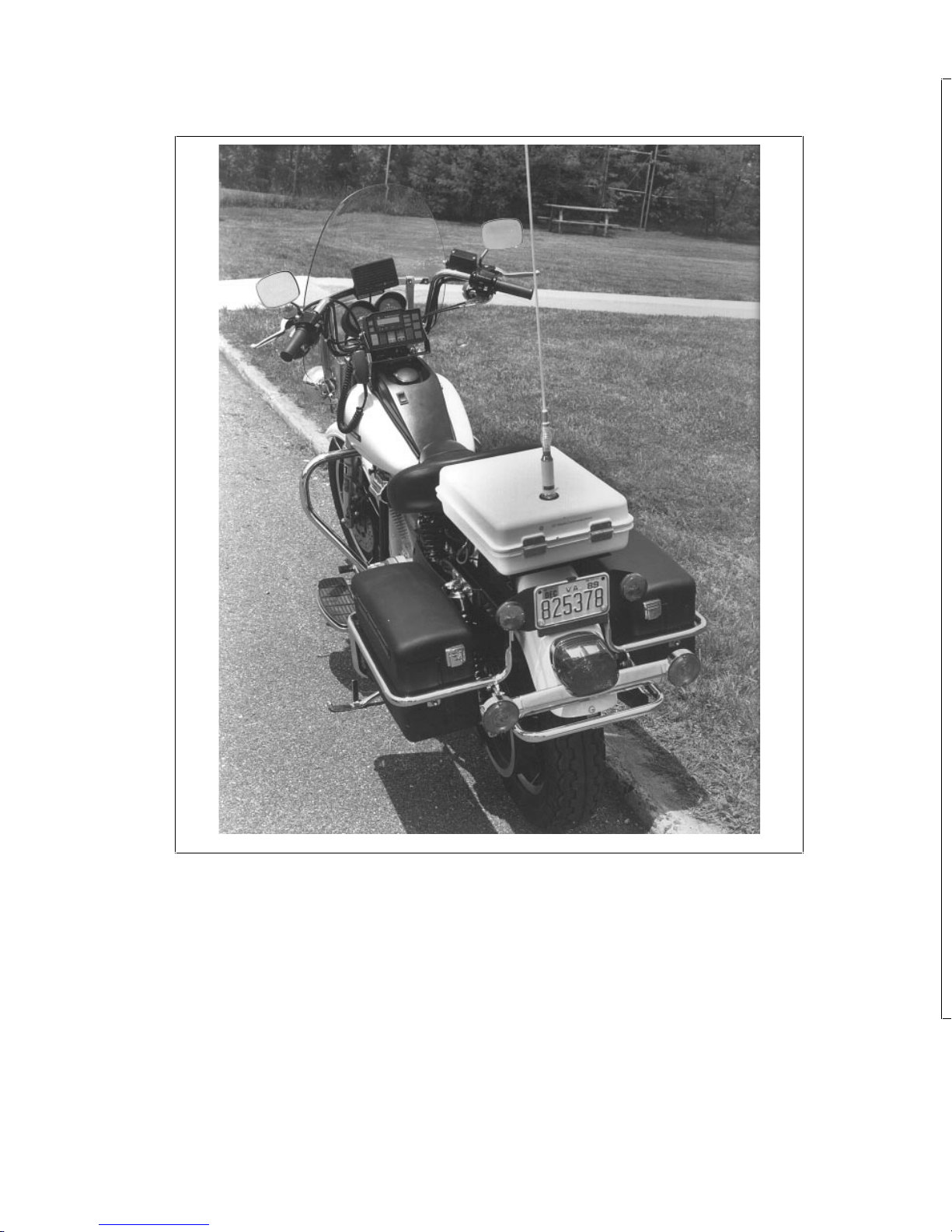
4
Figure 1. Typical S-825 Series Motorcycle Installation
33
Figure 23. Antenna Cutting Chart, 136-174 MHz

5
USER SUPPLIED EQUIPMENT:
• Motorcycle Mounting Bracket
• RTV
EQUIPMENT SUPPLIED:
• Weatherproof Box -19D438453G3
• Weatherproof case base mounting bracket - 19D438723P2
• Top Mounting Plate, 19D903777P1
• Bottom Mounting Plate, 19D903778P1
• RANGR Top Cover, 188D5003P1
• Rubber pad, 19B802204P1
• Installation Parts packet
• Rear Mount Antenna Support Bracket (Optional) - 19D904965
INSTALLATION
The standard Installation consists of the following:
• Mounting the S-825 control unit,
• Mounting the weatherproof base plate to the motorcycle bracket,
• Installing the outboard antenna bracket,
• Mounting the weatherproof case to the base plate,
• Running the power/control, vehicle system, and option cables,
• Installing the RANGR two-way radio in the weatherproof case,
and
• Installing the antenna on the weatherproof case or
• Installing the antenna on the L bracket.
All mounting hardware consists of stainless steel screws, locknuts, nuts,
and lockwashers for added reliability.
Optional equipment covered in this installation include the headset and
headset handlebar switch, noise canceling microphone, microphone
hang-up bracket and the antenna.

6
A typical S-825 Series Control Unit installation using a Harley-Davidson
motorcycle Model FXRP is shown in Figure 1.
EQUIPMENT
Standard equipment available for the S-825 Series installation includes the
following items:
• One of the following S-825 Series Control Units -
Select, Conventional 19D901146G3
Deluxe, Conventional 19D901146G4
EDACS Trunked 19D901146G5
EDACS Trunked w/ Scan 19D901146G6
• A 10-Foot Power/Control Cable 19D901739G5 (Option S8CC1L)
• EDACS System Cable 19D901864G2 (Option S8CC1X)
• Vehicle System Cable 19B219537G5 (Option S8CC1K)
• A low power RANGR two-way radio (refer to the Power vs.
Current chart in the Two Way Radio Mounting section of this
manual before installing).
• Weatherproof Fuse kit 19A149701G1 (Option S8PD1B)
• Weatherproof Case Assembly 19D438453G3 (Option S8RB1A)
• Weatherproof Case Mounting Plate Kit 19A149703G1 (Option
S8MA1D)
• Standard Microphone 19B801499P5 with Mounting Bracket
OR
• Noise Canceling Microphone 19B851815P2 (Option S8MC1G)
• Microphone Bracket with stronger spring 19A149690G1
(S8MN1G)
VENDOR DROP-SHIP OPTIONS
• Low Band, High Band, UHF, or 800 MHz Antenna.
31
Figure 21. Control Unit Accessories, Interconnection Diagram (con’t)

7
• Headset with Microphone, Handlebar Switch, and Belt-Mount
Amplifier.
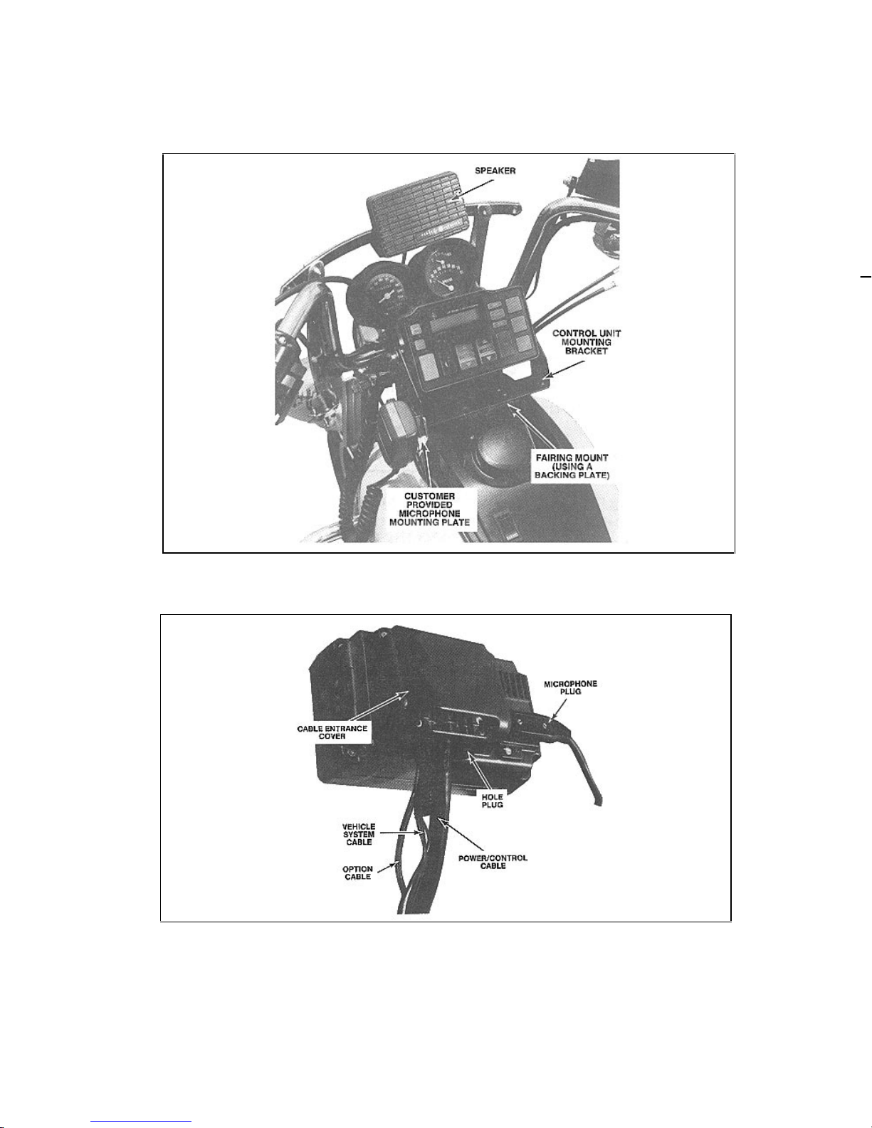
CONTROL UNIT MOUNTING
Mount the control unit within convenient reach of the operator, and where
it will not interfere with the safe operation of the motorcycle. A typical
control unit, microphone, and speaker mounting is shown in Figure 2.
Due to the large number of different motorcycle makes and models, i t is up
to the installer to decide how to mount the control unit, radio, and optional
equipment. Guidelines are provided for planning the installation.
The use of customer-designed "U" brackets, "L" brackets, mounting plates,
backing plates, or optional mounting kits from the motorcycle
manufacturer, if available, are suggested for mounting the control unit,
microphone, adaptor plate, weatherproof case, and radio. Existing bolts in
the frame and handlebar assembly may be utilized to mount the brackets
and mounting plates to the motorcycle.
Bracket material should be 1/8-inch steel minimum. When designing and
mounting the brackets, the following guidelines should be considered:
• The installation must NOT interfere with steering or operation of
the motorcycle.
• Mounting locations must NOT interfere with the driver or with
Instrument visibility.
• The installation should provide easy access to the radio operating
controls.
Be careful to avoid damaging some vital part of the
motorcycle if it becomes nessary to drill mounting holes.
Also, always check to see how far t he mounting screws
will extend below the mounting surface before installing
CAUTION
After installing the control unit, do not make any cable connections until
all cables have been run and secured, and the speaker and any option
connections have been made to the vehicle system plug. Speaker and
option connections are shown on the Interconnection Diagrams listed in
the Table of Contents. A typical control unit installation is shown in Figure
3.
8
After all cables are installed, refer to the Control Unit Interconnection
Diagrams in back of this manual for final connections to the control unit,
and for instructions to install the cable entrance cover kit.
Figure 2 Typical Control Unit and Speaker Mounting
Figure 3 - Typical Control Unit Installation
29
Figure 20. Control Unit and Radio Interconnection Diagram (con’t)

9
TWO-WAY RADIO MOUNTING
The installation of the two-way radio consists of:
• Mounting the base mounting plate to the motorcycle,
• Installing the radio mounting bracket in the weatherproof case,
• Installing the radio on the mounting bracket, and
• Connecting the power/control cable, cable ground lead, and
antenna lead once they have been installed.
• Modifying the RANGR radio for motorcycle installation, if
required.
POWER CONSIDERATIONS
The motorcycle may be equipped with additional lights, light flashers,
sirens, PA systems, etc. Therefore, consideration must be given to the
system current drain. It is recommended that the radios be set for the
applicable power output and current drain shown in Table 1 for all
RANGR motorcycle applications.
Do NOT use a high-powered radio in the motorcycle
application. To do so will result in damage to the
motorcycle alt ernat or, battery, and all circuits.
WARNING
MOUNTING THE RADIO
To install the radio in the weatherproof case:
Assembling the Weatherproof Box
1. Unpack the weatherproof motorcycle box, remove the key from the bag
attached to the bottom and open the box.
2. Remove the hardware kit (plastic bag), the bottom radio
mounting plate (19D903778P1) from the box by removing the
four 10-32 X 5/8” screws. The bottom mounting plate is the
smaller of the two. This will be installed in subsequent steps.
10
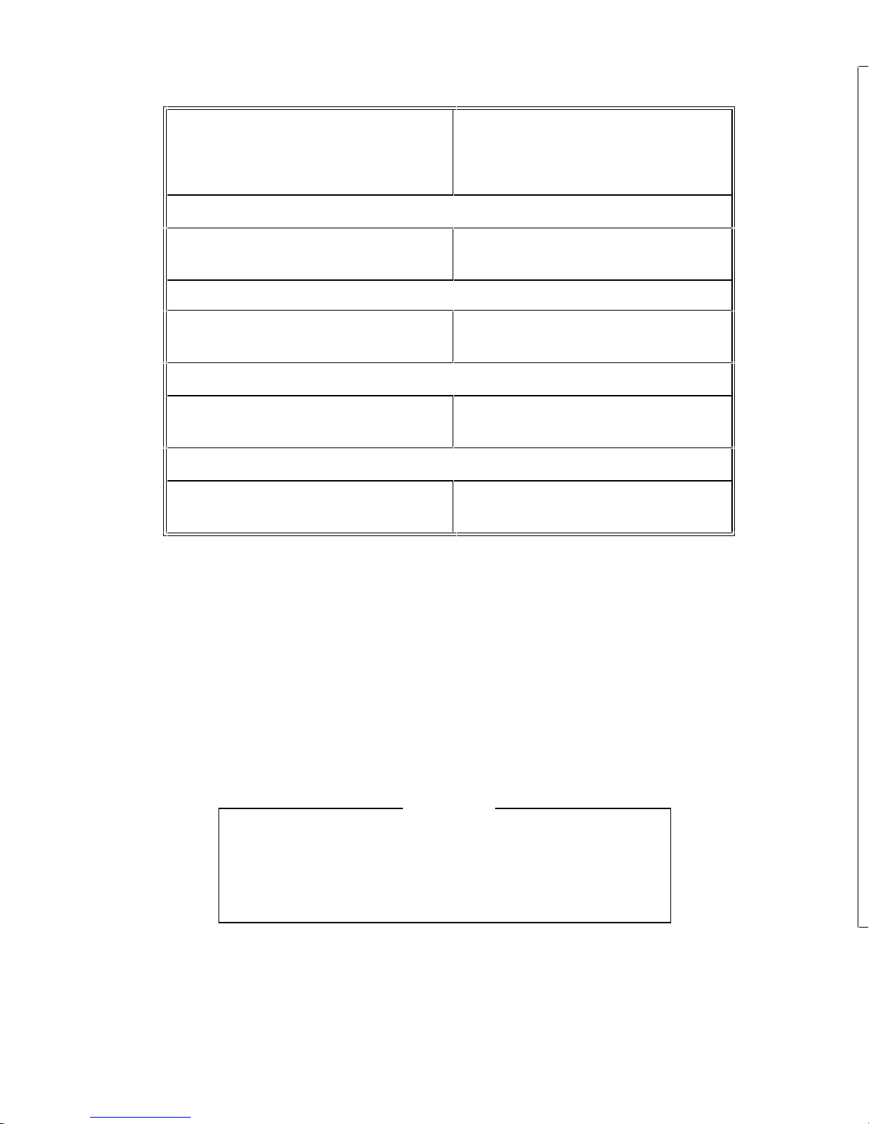
Table 1. Power vs. Current Setting
STANDARD RANGR RADIO
RATED POWER & CURRENT
Maximum & Typical
RANGR MOTORCYCLE
RADIO ADJUSTED POWER &
CURRENT Maximum & Typical
29-50 MHz
60 watts @ 13 Amps Maximum
(10.4 Amps Typical)
30 watts @ 9.5 Amps Maximum
(7.6 Amps Typical)
136-174 MHz
40 watts @13 Amps Maximum
(10 Amps Typical)
25 watts @10.5 Amps Maximum
(8 Amps Typical)
403-512 MHz
35/30 watts @13 Amps Maximum
(11 Amps Typical)l
25 watts @ 11 Amps Maximum
(9.4 Amps Typical)
806-870 MHz
35 watts @ 15 Amps Maximum
(10.4 Amps Typical)
25 watts @ 13 Amps Maximum
(9.1 Amps Typical)
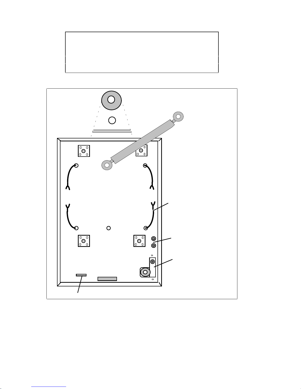
3. Insert the large rubber grommet into the metal cable cutout and slide
the cable cutout w/ grommet into the slot on the bottom of the
weatherproof box. Secure with the two 1/4 X 20 machine screws a nd
locking nuts provided. See Figure 4.
4. Insert the two smaller grommets into the two holes adjacent to the
cable cutout.
5. Remove the backing from the plastic wire holder. Locate a position on
the opposite side of the case from the cable cutout approximately 3/4inch from and parallel with the front and 2.5 inches from the outside
edge. Press the holder into position.
When installing the ground straps, be sure they are
dressed in such a way that they will not get pinched
between the mounting plate and the weatherproof box
when the shock absorbers are fully compressed.
NOTE
6. Install the four 4-inch radio ground straps (provided) with the
weatherproof case mounting screw through the ring terminal. The flat
side of the ring terminal should be face down.
27
Figure 19. Power Control Cable Outline Diagram
11
SERVICE TIP
After installation, force full compression of the shock
absorbers and observe the ground straps. If necessary
redress the ground straps to a position that allows full
compression without pinching. (Clearance is reduced
from 5/8” to approximately 1/4”.)
BRAIDED GROUND
RADIO
GROUND
CABLE
WIRE GUIDE
REAR MOUNT
ANTENNA OPTION
STRAP. ( USED IN TOP
POWER LEAD
ENTRANCE
CONTROL
ENTRANCE
MOUNT APPLICATIONS
ONLY)
Figure 4. Weatherproof Box Assembly
 Loading...