

RX8000 Series Receivers
Software Version 4.3.2
REFERENCE GUIDE
EN/LZT 790 0005 R1A

RX8000 Series Receivers
ENGLISH (UK) - READ THIS FIRST!
If you do not understand the contents of this manual. DO NOT OPERATE
THIS EQUIPMENT. Also, translation into any EC official language of this
manual can be made available, at your cost.
ITALIANO - LEGGERE QUESTO AVVISO PER PRIMO!
Se non si capisce il contenuto del presente manuale. NON UTILIZZARE
L’APPARECCHIATURA.. È anche disponibile la versione italiana di questo
manuale, ma il costo è a carico dell’utente.
SVENSKA - LÄS DETTA FÖRST!
Om Ni inte förstår informationen i denna handbok. ARBETA DÅ INTE MED
DENNA UTRUSTNING. En översättning till detta språk av denna handbok
kan också anskaffas, på Er bekostnad.
PORTUGUÊS - LEIA O TEXTO ABAIXO ANTES DE MAIS NADA!
Se não compreende o texto deste manual. NÃO UTILIZE O
EQUIPAMENTO. O utilizador poderá também obter uma tradução do
manual para o português à própria custa.
FRANÇAIS - AVANT TOUT, LISEZ CE QUI SUIT!
Si vous ne comprenez pas les instructions contenues dans ce manuel. NE
FAITES PAS FONCTIONNER CET APPAREIL. En outre, nous pouvons
vous proposer, à vos frais, une version française de ce manuel.
DEUTSCH - LESEN SIE ZUERST DIESEN HINWEIS!
Sollte Ihnen der Inhalf dieses Handbuches nicht klar verständlich sein,
dann. BEDIENEN SIE DIESE GERÄTE NICHT! Eine Übersetzung des
Handbuches in diese Sprache ist gegen Berechnung lieferbar.
ESPAÑOL - LEA ESTE AVISO PRIMERO!
Si no entiende el contenido de este manual. NO OPERE ESTE EQUIPO.
Podemos asimismo suministrarle una traducción de este manual al (idioma)
previo pago de una cantidad adicional que deberá abonar usted mismo.
NEDERLANDS - LEES DIT EERST!
Als u de inhoud van deze handleiding niet begrijpt. STEL DEZE
APPARATUUR DAN NIET IN WERKING. U kunt tevens, op eigen kosten,
Jos et ymmärrä käsikirjan sisältöä. ÄLÄ KÄYTÄ LAITETTA. Käsikirja
Udstyret må ikke betjenes. MEDMINDRE DE TIL FULDE FORSTÅR
INDHOLDET AF DENNE HÅNDBOG. Vi kan også for Deres regning levere
Αν δεν καταλάβετε το περιεχόμενο αυτού του βοηθήματος/εγχειριδίου. ΜΗΝ
ΛΕΙΤΟΥΡΓΗΣΕΤΕ ΑΥΤΟΝ ΤΟΝ ΕΞΟΠΛΙΣΜΟ. Επίσης, αυτό το εγχειρίδιο
είναι διαθέσιμο σε μετάφραση σε αυτή τη γλώσσα και μπορείτε να το
een vertaling van deze handleiding krijgen.
SUOMI - LUE ENNEN KÄYTTÖÄ!
voidaan myös suomentaa asiakkaan kustannuksella.
DANSK - LÆS DETTE FØRST!
en dansk oversættelse af denne håndbog.
ΕΛΛΗΝΙΚΑ - ΔΙΑΒΑΣΤΕ ΠΡΩΤΑ ΑΥΤΟ!
αγοράσετε.
Copyright
© Copyright Ericsson AB 2011. All rights reserved.
Disclaimer
No part of this document may be reproduced in any form without the written permission of the
copyright owner.
The contents of this document are subject to revision without notice due to continued progress in
methodology, design and manufacturing. Ericsson shall have no liability for any error or damage of
any kind resulting from the use of this document.
ii
EN/LZT 790 0005 R1A 2011-03-30

Contents
Contents
Chapter 1: Introduction
This chapter identifies the equipment versions covered by this manual, describes
the purpose of the equipment and provides a summary of features, controls and
indicators.
Chapter 2: Installing the Equipment
This chapter provides a guide to the installation requirements, gives detailed
procedures for the installation and configuration of the equipment including
important safety information and provides details of connectors.
Chapter 3: Front Panel Control
This chapter details the power up/down procedures and describes the Front Panel
LCD menus used for setting-up, configuring and operating the equipment.
Chapter 4: Remote Control
This chapter describes the different ways in which the equipment may be configured
and operated remotely.
Chapter 5: Web Browser Control
This chapter describes the Web Browser graphical user interface used for detailed
configuration and operation of the equipment.
Chapter 6: Options
This chapter describes the available hardware and software options for the
equipment.
Chapter 7: Preventive Maintenance and Fault-finding
This chapter provides details of routine maintenance and servicing, including
warranty and maintenance information, and details fault-finding information for other
types of problem which may be encountered.
Annex A: Glossary
Annex B: Technical Specification
Annex C: Language Abbreviations
EN/LZT 790 0005 R1A 2011-03-30
iii

Preliminary Pages
Introduction
This Reference Guide provides instructions and information for the installation and
operation of the RX8000 Receiver range.
This Reference Guide should be kept in a safe place for reference for the life of the
equipment. It is not intended that this Reference Guide will be amended by the issue
of individual pages. Any revision will be by a complete re-issue. Further copies of
this Reference Guide can be ordered from the address shown on page vii .If passing
the equipment to a third party, also pass the relevant documentation.
Revision History
Issues of this Reference Guide are listed below:
Issue Date Software Version Comments
1
2
A
April
2009
Jan
2011
March
2011
1.3.0
4.3.2
4.3.2
Initial release for RX8000 Receiver Range
(Supersedes E10261) Inclusion of RX8200
(Sv 2.0.0) Information
Template restyled to Ericsson corporate style.
New features and option cards added,
including DVB-S2, IP Input, 8VSB and G703.
Allocation of Ericsson Document Identity and
re-brand completion.
Associated Documents
The following manuals/guides are also associated with this equipment:
Ericsson Document
Identity
2/1424-EN/LZT 790 0008 ST.US.E10262 RX8320 User Guide
1/1424-EN/LZT 790 0008 ST.US.E10274 RX8310/15/30 User Guide
Original Document
Number
Title
iv
1424-EN/LZT 790 0009 ST.US.E10287 RX8200 User Guide
Trademarks
All best endeavors have been made to acknowledge registered trademarks and
trademarks used throughout this Reference Guide. Any notified omissions will be
rectified in the next issue of this Reference Guide. Some trademarks may be
registered in some jurisdictions but not in others.
EN/LZT 790 0005 R1A 2011-03-30

Preliminary Pages
v
Registered trademarks and trademarks used are acknowledged below and marked
with their respective symbols. However, they are not marked within the text of this
Reference Guide.
Registered Trademarks
Ethernet
Dolby
®
Registered trademark of Xerox Corporation.
®
/AC-3® Registered trademarks of Dolby Laboratories Licensing
Corporation.
Dolby
®
Digital Registered trademark of Dolby Laboratories Licensing
Corporation.
Macrovision
This product incorporates copyright protection technology that is protected by U.S.
patents and other intellectual property rights. Use of this copyright protection
technology must be authorized by Macrovision Corporation, and is intended for
home and other limited viewing uses only unless authorized by Macrovision.
Reverse engineering or disassembly is prohibited.
Warnings, Cautions and Notes
Heed Warnings
All warnings on the product and in the operating instructions should be adhered to.
The manufacturer can not be held responsible for injuries or damage where
warnings and cautions have been ignored or taken lightly.
Read Instructions
All the safety and operating instructions should be read before this product is
operated.
Follow Instructions
All operating and use instructions should be followed.
Retain Instructions
The safety and operating instructions should be retained for future reference.
EN/LZT 790 0005 R1A 2011-03-30

Preliminary Pages
Warning!
Warnings give information which, if strictly observed, will prevent personal injury or
death, or damage to property or the environment. They are highlighted for
emphasis, as in this example, and are placed immediately preceding the point at
which the reader requires them.
Caution!
Cautions give information which, if strictly followed, will prevent damage to
equipment or other goods. They are highlighted for emphasis, as in this example,
and are placed immediately preceding the point at which the reader requires them.
Note: Notes provide supplementary information. They are highlighted for
emphasis, as in this example, and are placed immediately after the relevant
text.
EMC Compliance
This equipment is certified to the EMC requirements detailed in Annex B, Technical
Specification. To maintain this certification, only use the leads supplied or if in doubt
contact Customer Services.
Contact Information
Support Services
Our primary objective is to provide first class customer care that is tailored to your
specific business and operational requirements. All levels are supported by one or
more service performance reviews to ensure the perfect partnership between
Ericsson and your business.
Warranty
All Ericsson products and systems are designed and built to the highest standards
and are covered under a comprehensive 12 month warranty.
Levels of Continuing Ericsson Service Support
vi
For standalone equipment, then Ericsson BASIC Essential support is the value for
money choice for you. BASIC provides you with year-by-year Service long after the
warranty has expired.
EN/LZT 790 0005 R1A 2011-03-30

Preliminary Pages
m
For systems support you can choose either Gold Business Critical support or
Silver Business Advantage. These packages are designed to save you costs and
protect your income through enlisting the help of Ericsson support specialists.
Call Ericsson Customer Services for more details.
Customer Services
Europe, Middle East
and Africa
Americas Tel: +888 671 1268
China Tel: +86 10 8476 8676
Australia and New
Zealand
Internet Address
Tel: +44 (0) 23 8048 4455
Fax: +44 (0) 23 8048 4467
Email: tvsupportemea@ericsson.com
Tel: +678 812 6255
Fax: +678 812 6262
Email: tvsupportamericas@ericsson.co
Email: tvsupport@ericsson.com
Fax: +86 10 8476 7741
Tel: +852 2590 2388
Fax: +852 2590 9550
Email: tvsupportapac@ericsson.com
Tel: +612 (0) 9111 4027
Fax: +612 (0) 9111 4949
Email: tvsupportanz@ericsson.com
www.ericsson.com
US and Canada
International
Compression
Software Support Centre
Beijing
Beijing
Hong Kong
Hong Kong
Technical Training
Ericsson provides a wide range of training courses on the operation and
maintenance of our products and on their supporting technologies. Ericsson can
provide both regularly scheduled courses and training tailored to individual needs.
Courses can be run either at your premises or at one of our dedicated training
facilities.
International Tel: +44 (0) 23 8048 4229
Fax: +44 (0) 23 8048 4161
Email: tvglobaltraining@ericsson.com
Customer Services and Technical Training Postal Address
Ericsson
Unit 2
Strategic Park
Comines Way
Hedge End
Southampton
Hampshire
SO30 4DA
United Kingdom
EN/LZT 790 0005 R1A 2011-03-30
vii

Preliminary Pages
Return of Equipment
If you need to return equipment for repair please contact your local Ericsson
Customer Services Department. Please refer to the Customer Services contact
information on page vii.
You will then be directed to return the faulty equipment to a repair centre with
the appropriate facilities for that equipment. A tracking number will be issued that
should be used if you need to enquire about the progress of the repair. The
equipment should be properly packed and the tracking number should be clearly
marked on the outside of the packaging
.
Technical Publications
If you need to contact Ericsson Technical Publications regarding this publication,
e-mail: tvtechpubs@ericsson.com.
viii
EN/LZT 790 0005 R1A 2011-03-30

1 Introduction
Chapter 1
Contents
1.1 Introduction ...........................................................................................1-3
1.1.1 Who Should Use this Reference Guide................................................ 1-3
1.1.2 What Equipment is Covered by this Reference Guide .........................1-3
1.2 Summary of Features .........................................................................1-10
1.2.1 RX8200 Advanced Modular Receiver ................................................1-10
1.2.1.1 RX82XX (and RX83XX) Standard Base Features.............................. 1-10
1.2.1.2 RX8200 Factory Fit Optional Hardware Features...............................1-11
1.2.1.3 RX8200 Optional Software Features.................................................. 1-11
1.2.2 RX8310 Distribution Receiver ............................................................1-12
1.2.2.1 RX8310 Standard Base Features....................................................... 1-12
1.2.2.2 RX8310 Factory Fit Optional Hardware Features...............................1-12
1.2.2.3 RX8310 Optional Software Features.................................................. 1-12
1.2.3 RX8315 Distribution Receiver ............................................................1-13
1.2.3.1 RX8315 Standard Base Features....................................................... 1-13
1.2.3.2 RX8315 Factory Fit Optional Hardware Features...............................1-13
1.2.3.3 RX8315 Optional Software Features.................................................. 1-13
1.2.4 RX8320 ATSC Broadcast Receiver.................................................... 1-14
1.2.4.1 RX8320 Standard Base Features....................................................... 1-14
1.2.4.2 RX8320 Factory Fit Optional Hardware Features...............................1-15
1.2.4.3 RX8320 Optional Software Features.................................................. 1-15
1.2.5 RX8330 Distribution Receiver ............................................................1-15
1.2.5.1 RX8330 Standard Base Features....................................................... 1-15
1.2.5.2 RX8330 Factory Fit Optional Hardware Features...............................1-16
1.2.5.3 RX8330 Optional Software Features.................................................. 1-16
1.3 The Satellite Receiver ........................................................................ 1-17
1.3.1 Typical Satellite System .....................................................................1-17
1.3.2 Input Connections............................................................................... 1-17
1.3.3 What the Satellite Receiver Does....................................................... 1-18
1.4 The Telco Receiver/Decoder .............................................................. 1-19
1.4.1 Typical Decoder System..................................................................... 1-19
1.4.2 What the Decoder Does .....................................................................1-19
1.5 Construction ....................................................................................... 1-20
1.6 Front Panel ......................................................................................... 1-20
1.7 Rear Panels ........................................................................................1-22
EN/LZT 790 0005 R1A
1-1

Chapter 1
List of Figures
Figure 1.1
Typical Satellite Compression System............................................... 1-17
Figure 1.2 What the Satellite Receiver Does....................................................... 1-18
Figure 1.3 Typical Compression System............................................................. 1-19
Figure 1.4 Role of the Decoder ........................................................................... 1-20
Figure 1.5 Front Panel Controls (RX8200).......................................................... 1-21
Figure 1.6 Rear Panels (RX8200, RX8310, RX8315, RX8320 and RX8330) ..... 1-22
List of Tables
Table 1.1
Equipment Model Descriptions............................................................. 1-3
Table 1.2 RX8200 Hardware Options .................................................................. 1-4
Table 1.3 RX8200 Software Options.................................................................... 1-5
Table 1.4 RX8310 Hardware Options .................................................................. 1-6
Table 1.5 RX8310 Software Options.................................................................... 1-6
Table 1.6 RX8315 Hardware Options .................................................................. 1-7
Table 1.7 RX8315 Software Options.................................................................... 1-7
Table 1.8 RX8320 Hardware Options .................................................................. 1-8
Table 1.9 RX8320 Software Options.................................................................... 1-8
Table 1.10 RX8330 Hardware Options .................................................................. 1-9
Table 1.11 RX8330 Software Options.................................................................... 1-9
Table 1.12 Front Panel Controls .......................................................................... 1-21
Table 1.13 Rear Panels ....................................................................................... 1-23
1-2
EN/LZT 790 0005 R1A
Chapter 1
1.1 Introduction
1.1.1 Who Should Use this Reference Guide
This Reference Guide is written for operators / users of the RX8000 Series
Receivers. It describes the units’ functions and operation. The Reference Guide is
written to assist in the installation and day-to-day care and operation of the unit.
Maintenance information requiring the covers to be removed is not included.
Warning!
Do not remove the covers of this equipment. Hazardous voltages are present within
this equipment and may be exposed if the covers are removed. Only Ericsson
trained and approved service engineers are permitted to service this equipment.
Caution!
Unauthorized maintenance or the use of non-approved replacements may affect the
equipment specification and invalidate any warranties.
1.1.2 What Equipment is Covered by this Reference Guide
Table 1.1 Equipment Model Descriptions
Model
Number
RX8200 RX8200/BAS
RX8252 RX8252/BAS
RX8310 RX8310/BAS
RX8315 RX8315/BAS
Marketing
Code
RX8200/BAS/2
Price Object
Number
FAZ 101 0113/1
FAZ 101 0113/2
FAZ1010113/62 KDU137769/1 Program Transcoder. DVB-S2, Common
FAZ1010108/18 KDU137620/1 Distribution Receiver. DVB-S2, Director
FAZ 101 0108/19
Supply Object
Description
Number
KDU 137 639/1
KDU 137 639/2
KDU137599/1 Distribution Receiver. DVB-S2, Common
Advanced Modular Receiver.
MPEG-2/MPEG-4 HD/SD, AC Power Supply.
MPEG-2/MPEG-4 4:2:2, AC Power Supply.
Interface, AC Power Supply.
CA, AC Power Supply.
Interface CA, Director CA, AC Power
Supply.
RX8320 RX8320/BAS
RX8330 RX8330/BAS
EN/LZT 790 0005 R1A
FAZ 101 0108/20
FAZ 101 0108/1 KDU 137 337/1 Distribution Receiver. DVB-S2, Common
KDU137619/1 ATSC Broadcast Receiver. 8-VSB, MPEG-
2 Decode, AC-3, AC Power Supply.
Interface CA, Director CA, SDI Output,
Power Supply.
AC
1-3

Chapter 1
This Reference Guide covers the functions of software version 4.3.2 and later.
To verify the installed version either:
• Access the front panel System Menu (Menu 1.2.1). The front panel menus are
described in Chapter 3, Front Panel Control.
• Access the Web Browser screens and select the About button. The Web
Browser screens are described in Chapter 5, Web Browser Control.
The various hardware and software options are listed below:
Table 1.2 RX8200 Hardware Options
Marketing Code Price Object
Number
RX8200/HWO/DVBS2 FAZ 101 0113/5 ROA 128 3757 DVB-S2 Input Card
RX8200/HWO/IP/GIGE FAZ 101 0113/12 ROA 128 3761 Gigabyte 100/1000BaseT Ethernet
RX8200/HWO/G703 FAZ 101 0113/8 ROA 128 3763 G.703 ATM Input Card
RX8200/HWO/MP2/422 FAZ 101 0113/15 ROA 128 3765
RX8200/HWO/IP/OUT FAZ 101 0113/14 ROA 128 3756
RX8200/HWO/SD FAZ 101 0113/18 ROA 128 3758
RX8200/HWO/HD/3G FAZ 101 0113/10 ROA 128 3768
RX8200/HWO/RS232 FAZ 101 0113/17 ROA 128 4207 Remote Data Card
RX8200/HWO/BSKYB FAZ 101 0113/4 ROA 128 4203 NDS BSKYB CA Card
RX8200/HWO/BAL/AUD FAZ 101 0113/3 ROA 128 3760
Supply Object
Number
Description
MPEG-2 4:2:2 Decode Card with
only SD Decode Enabled
Dual Gigabit IP Transport Stream
Output Card
SD Video Input and ASI Output
Card with 2x CVBS, 2x
Connectors for ASI/SDI
HD and SD Video Input and ASI
Output Card
Balanced Analogue and Digital
Audio Output Providing 2 Stereo
Pairs of Audio
RX8200/HWO/DVBS2/2 FAZ 101 0113/6 ROA 128 3762
RX8200/HWO/HQDCONV FAZ 101 0113/60 ROA 128 4419 High-Quality Down-Conversion
RX8XXX/CABLE/XLR FAZ 101 0108/24 RPM 901 364
RX8XXX/CABLE/SCRTRM FAZ 101 0108/23 RPM 901 365
1-4
EN/LZT 790 0005 R1A
2nd Gen DVB-S & DVB-S2
Satellite Input Option
XLR Terminal Audio Break-out
Cable
Screw Terminal Audio Break-out
Cable

Chapter 1
Table 1.3 RX8200 Software Options
Marketing Code Price Object
Number
Supply Object
Number
Description
RX8200/SWO/DVBS2/QPSK FAZ 101 0113/32 FAT 102 0151 DVB-S2 QPSK License key
RX8200/SWO/DVBS2/8PSK FAZ 101 0113/30 FAT 102 0152 DVB-S2 8PSK License key
RX8200/SWO/DVBS2/LSYM
FAZ 101 0113/31
FAT 102 0153
DVB-S2 Low Symbol Rate License
Key
RX8200/SWO/MPEG2/SD FAZ 101 0113/45 FAT 102 0169 MPEG-2 SD Decoding
RX8200/SWO/MPEG2/HD FAZ 101 0113/44 FAT 102 0170 MPEG-2 HD & SD Decoding
RX8200/SWO/MP2/MP4/SD FAZ 101 0113/40 FAT 102 0171 MPEG-2 & MPEG-4 SD Decode
RX8200/SWO/MP2/MP4/SD/HD FAZ 101 0113/41 FAT 102 0156
MPEG-2 & MPEG-4 HD and SD
Decode
RX8200/SWO/SING/SERVFILT FAZ 101 0113/53 FAT 102 0181 Single Service Filtering
RX8200/SWO/MULT/SERVFILT FAZ 101 0113/47 FAT 102 0182 Multi-Service Filtering
RX8200/SWO/TTV FAZ 101 0113/58 FAT 102 0168
Signal Protection Scrambling
License
RX8200/SWO/IP/DATA FAZ 101 0113/35 FAT 102 0183 High Speed Data Output
RX8200/SWO/PW FAZ 101 0113/51 FAT 102 0154
Password Protection for Web
Browser
RX8200/SWO/DIR5 FAZ 101 0113/27 FAT 102 0155 Director Single-Service CA
RX8200/SWO/DIR5/MSD FAZ 101 0113/28 FAT 102 0166
Director Multi-Service
Descrambling
RX8200/SWO/MSD FAZ 101 0113/46 FAT 102 0165
Common Interface Multi Service
Descrambling
RX8200/SWO/AC3 FAZ 101 0113/22 FAT 102 0158
Dolby Digital
®
Decoding / Down-
mixing
RX8200/SWO/AAC FAZ 101 0113/21 FAT 102 0179 AAC Decode
RX8200/SWO/NULL FAZ 101 0113/48 FAT 102 0161 Null Packet TS License
RX8200/SWO/RAS FAZ 101 0113/52 FAT 102 0164 RAS CA
RX8200/SWO/CI FAZ 101 0113/25 FAT 102 0162
Common Interface CA SingleService Decryption
RX8200/SWO/BISS FAZ 101 0113/23 FAT 102 0163 BISS Mode 1 & E CA
RX8200/SWO/BISS/MSD FAZ 101 0113/24 FAT 102 0167 BISS Multi-Service Descrambling
RX8200/SWO/IP/PROMPEG FAZ 101 0113/37 FAT 102 0159 SMPTE 2022 Pro-MPEG FEC
RX8200/HWO/HD/3G FAZ 101 0113/10 ROA 128 3769
EN/LZT 790 0005 R1A
HD OUTPUT CARD+1xCVBS,
1xRGB, 3x3G Connectors
1-5

Chapter 1
Marketing Code Price Object
Number
RX8200/SWO/HDSDI/3G FAZ 101 0113/34 FAT 102 0176
RX8200/SWO/MP2/422/SD FAZ 101 0113/59 FAT 102 0387 MPEG-2 SD 4:2:2 Decoding
RX8200/SWO/MP2/HD/422 FAZ 101 0113/39 FAT 102 0172 MPEG-2 HD and SD 4:2:2 Decode
RX8200/SWO/MP4/422/SD FAZ 101 0113/43 FAT 102 0178 MPEG-4 SD 4:2:2 Decoding
RX8200/SWO/MP4/422/HD FAZ 101 0113/42 FAT 102 0177 MPEG-4 HD 4:2:2 Decoding
RX8200/SWO/DCONV FAZ 101 0113/26 FAT 102 0157
RX8200/SWO/UPCONV FAZ 101 0113/54 FAT 102 0174
RX8200/SWO/XCONV FAZ 101 0113/55 FAT 102 0175 Cross-conversion
RX8200/SWO/FSYNC FAZ 101 0113/33 FAT 102 0160 Frame Sync
RX8200/SWO/4AUD FAZ 101 0113/20 FAT 102 0180 4 x Audio Capacity
RX8200/SWO/LDELAY FAZ 101 0113/38
Supply Object
Number
FAT 102 0173
Description
MPEG-4 HD 4:2:2 1080p 50/60
Decoding
Simultaneous Down-conversion of
HD to SD
Up-conversion from SD to HD (to
1080i or 720p)
Low Latency Decode
Table 1.4 RX8310 Hardware Options
Marketing Code Price Object
Number
RX83XX/HWO/IP/OUT FAZ 101 0108/22 ROA 128 3646
RX8XXX/CABLE/XLR FAZ 101 0108/24 RPM 901 364
RX8XXX/CABLE/SCRTRM FAZ 101 0108/23 RPM 901 365
Supply Object
Number
Description
Dual Gigabit IP Transport Stream
Output Card
XLR Terminal Audio Break-out
Cable
Screw Terminal Audio Break-out
Cable
Table 1.5 RX8310 Software Options
Marketing Code Price Object
Number
RX83XX/SWO/DVBS2/QPSK FAZ 101 0108/6 FAT 102 0098 DVB-S2 QPSK License Key
RX83XX/SWO/DVBS2/8PSK FAZ 101 0108/4 FAT 102 0102 DVB-S2 8PSK License Key
RX83XX/SWO/DVBS2/LSYM FAZ 101 0108/5 FAT 102 0103
RX83XX/SWO/MPEG2/SD FAZ 101 0108/10 FAT 102 0105 MPEG-2 SD Decoding
Supply Object
Number
Description
DVB-S2 Low Symbol Rate License
Key
RX83XX/SWO/MPEG2/HD FAZ 101 0108/9 FAT 102 0106 MPEG-2 HD & SD Decoding
RX83XX/SWO/AC3 FAZ 101 0108/28 FAT 102 0107
1-6
EN/LZT 790 0005 R1A
Dolby Digital® Decoding / Downmixing

Chapter 1
Marketing Code Price Object
Number
RX83XX/SWO/PW FAZ 101 0108/29 FAT 102 0110
RX83XX/SWO/AAC FAZ 101 0108/2 FAT 102 0370 AAC Decode
RX83XX/SWO/SING/SERVFILT FAZ 101 0108/15 FAT 102 0138 Single Service Filtering
RX83XX/SWO/MULT/SERVFILT FAZ 101 0108/14 FAT 102 0137 Multi-Service Filtering
RX83XX/SWO/IP/DATA FAZ 101 0108/7 FAT 102 0113 High Speed Data Output
RX83XX/SWO/MP2/MP4/SD FAZ 101 0108/12 FAT 102 0111 MPEG-2/4 SD 4:2:0 Decoding
RX83XX/SWO/MP2/MP4/SD/HD FAZ 101 0108/11 FAT 102 0112 MPEG-2/4 HD 4:2:0 Decoding
RX83XX/SWO/NULL FAZ 101 0108/17 FAT 102 0114 Null Packet TS License
RX83XX/SWO/DIR5/MSD FAZ 101 0108/3 FAT 102 0104
Supply Object
Number
Description
Password Protection for Web
Browser
Director Multi-Service
Descrambling
Table 1.6 RX8315 Hardware Options
Marketing Code Price Object
Number
Supply Object
Number
Description
RX83XX/HWO/IP/OUT FAZ 101 0108/22 ROA 128 3646
RX8XXX/CABLE/XLR FAZ 101 0108/24 RPM 901 364
RX8XXX/CABLE/SCRTRM FAZ 101 0108/23 RPM 901 365
Dual Gigabit IP Transport Stream
Output Card
XLR Terminal Audio Break-out
Cable
Screw Terminal Audio Break-out
Cable
Table 1.7 RX8315 Software Options
Marketing Code Price Object
Number
RX83XX/SWO/DVBS2/QPSK FAZ 101 0108/6 FAT 102 0098 DVB-S2 QPSK License Key
RX83XX/SWO/DVBS2/8PSK FAZ 101 0108/4 FAT 102 0102 DVB-S2 8PSK License Key
RX83XX/SWO/DVBS2/LSYM FAZ 101 0108/5 FAT 102 0103
RX83XX/SWO/MPEG2/SD FAZ 101 0108/10 FAT 102 0105 MPEG-2 SD Decoding
RX83XX/SWO/MPEG2/HD FAZ 1010108/9 FAT 102 0106 MPEG-2 HD & SD Decoding
RX83XX/SWO/AC3 FAZ 101 0108/28 FAT 102 0107
Supply Object
Number
Description
DVB-S2 Low Symbol Rate License
Key
Dolby Digital® Decoding / Downmixing
RX83XXSWO/PW FAZ 101 0108/29 FAT 102 0110
RX83XX/SWO/AAC FAZ 101 0108/2 FAT 102 0370 AAC Decode
EN/LZT 790 0005 R1A
Password Protection for Web
Browser
1-7

Chapter 1
Marketing Code Price Object
Number
RX83XX/SWO/SING/SERVFILT FAZ 101 0108/15 FAT 102 0138 Single Service Filtering
RX83XX/SWO/MULT/SERVFILT FAZ 101 0108/14 FAT 102 0137 Multi-Service Filtering
RX83XX/SWO/IP/DATA FAZ 101 0108/7 FAT 102 0113 High Speed Data Output
RX83XX/SWO/MP2/MP4/SD FAZ 101 0108/12 FAT 102 0111 MPEG-2/4 SD 4:2:0 Decoding
RX83XX/SWO/MP2/MP4/SD/HD FAZ 101 0108/11 FAT 102 0112 MPEG-2/4 HD 4:2:0 Decoding
RX83XX/SWO/NULL FAZ 101 0108/17 FAT 102 0114 Null Packet TS License
RX83XX/SWO/MSD FAZ 101 0108/3 FAT 102 0125
Supply Object
Number
Description
Common Interface Multi-Service
Descrambling
Table 1.8 RX8320 Hardware Options
Marketing Code Price Object
Number
RX8XXX/CABLE/XLR FAZ 101 0108/24 RPM 901 364
RX8XXX/CABLE/SCRTRM FAZ 101 0108/23 RPM 901 365
Supply Object
Number
Description
XLR Terminal Audio Break-out
Cable
Screw Terminal Audio Break-out
Cable
Table 1.9 RX8320 Software Options
Marketing Code Price Object
Number
RX83XX/SWO/AC3 FAZ 101 0108/28 FAT 102 0107
RX83XX/SWO/PW FAZ 101 0108/29 FAT 102 0110
RX83XX/SWO/AAC FAZ 101 0108/2 FAT 102 0370 AAC Decode
RX83XX/SWO/SING/SERVFILT FAZ 101 0108/15 FAT 102 0138 Single-Service Filtering
RX83XX/SWO/MULT/SERVFILT FAZ 101 0108/14 FAT 102 0137 Multi-Service Filtering
RX83XX/SWO/IP/DATA FAZ 101 0108/7 FAT 102 0113 High Speed Data Output
RX83XX/SWO/MP2/MP4/SD FAZ 101 0108/12 FAT 102 0111
RX83XX/SWO/MP2/MP4/SD/HD FAZ 101 0108/11 FAT 102 0112
RX83XX/SWO/MPEG4/SD FAZ 101 0108/10 FAT 102 0105 MPEG-4 SD 4:2:0 Decoding
Supply Object
Number
Description
®
Dolby Digital
mixing
Password Protection for Web
Browser
MPEG-2, MPEG-4 4:2:0 SD
Decoding
MPEG-2, MPEG-4, 4:2:0 SD
Decoding and HD Downconversion
Decoding / Down-
RX83XX/SWO/MPEG4/HD FAZ 101 0108/9 FAT 102 0106 MPEG-4 HD 4:2:0 Decoding
1-8
EN/LZT 790 0005 R1A

Chapter 1
Marketing Code Price Object
Number
RX83XX/SWO/NULL FAZ 101 0108/17 FAT 102 0114 Null Packet TS License
RX8320/SWO/IP/OUT FAZ 101 0108/25 FAT 102 0134
RX8320/UPG/IP/OUT FAZ 101 0108/26 FAT 102 0135 IP Transport Stream Output
Supply Object
Number
Description
IP Transport Stream Out License
Key
Table 1.10 RX8330 Hardware Options
Marketing Code Price Object
Number
RX83XX/HWO/RSECAM FAZ 101 0108/33
RX83XX/HWO/IP/OUT FAZ 101 0108/22 ROA 128 3646
RX8XXX/CABLE/XLR FAZ 101 0108/24 RPM 901 364
RX8XXX/CABLE/SCRTRM FAZ 101 0108/23 RPM 901 365
Supply Object
Number
ROA 128 4418
Description
Russian SECAM Output Card
Dual Gigabit IP Transport Stream
Output Card
XLR Terminal Audio Break-out
Cable
Screw Terminal Audio Break-out
Cable
Table 1.11 RX8330 Software Options
Marketing Code Price Object
Number
RX83XX/SWO/DVBS2/QPSK FAZ 101 0108/6 FAT 102 0098 DVB-S2 QPSK License Key
RX83XX/SWO/DVBS2/8PSK FAZ 101 0108/4 FAT 102 0102 DVB-S2 8PSK License Key
RX83XX/SWO/DVBS2/LSYM FAZ 101 0108/5 FAT 102 0103 DVB-S2 Low Symbol Rate License
RX83XX/SWO/MPEG2/SD FAZ 101 0108/10 FAT 102 0105 MPEG-2 SD Decoding
RX83XX/SWO/MPEG2/HD FAZ 101 0108/9 FAT 102 0106 MPEG-2 HD & SD Decoding
RX83XX/SWO/AC3 FAZ 101 0108/28 FAT 102 0107
RX83XX/SWO/PW FAZ 101 0108/29 FAT 102 0110
RX83XX/SWO/AAC FAZ 101 0108/2 FAT 102 0370 AAC Decode
RX83XX/SWO/BISS FAZ 101 0108/30 FAT 102 0132 BISS Modes 1 and E
RX83XX/SWO/BISS/MSD FAZ 101 0108/16 FAT 102 0133
Supply Object
Number
Description
Dolby Digital® Decoding / Downmixing
Password Protection for Web
Browser
BISS Modes 1 and E Multi-Service
Decryption
RX83XX/SWO/SING/SERVFILT FAZ 101 0108/15 FAT 102 0138 Single Service Filtering
RX83XX/SWO/MULT/SERVFILT FAZ 101 0108/14 FAT 102 0137 Multi-Service Filtering
RX83XX/SWO/IP/DATA FAZ 101 0108/7 FAT 102 0113 High Speed Data Output
EN/LZT 790 0005 R1A
1-9

Chapter 1
Marketing Code Price Object
Number
RX83XX/SWO/MP2/MP4/SD FAZ 101 0108/12 FAT 102 0111 MPEG-2/4 SD 4:2:0 Decoding
RX83XX/SWO/MP2/MP4/SD/HD FAZ 101 0108/11 FAT 102 0112 MPEG-2/4 HD 4:2:0 Decoding
RX83XX/SWO/NULL FAZ 101 0108/17 FAT 102 0114 Null Packet TS License
RX83XX/SWO/MSD FAZ 101 0108/13 FAT 102 0125
RX83XX/SWO/DIR5/MSD FAZ 101 0108/3
Supply Object
Number
FAT 102 0104
Description
Common Interface Multi-Service
Descrambling
Director Multi-Service
Descrambling
1.2 Summary of Features
The RX8000 Series Receivers are single-service Decoders designed for the
distribution of video services throughout a large network. They provide an advanced
feature set combining maximum transmission efficiency with uncomplicated remote
management. They provide all the essential functionality and connectivity options
required to satisfy the requirements of cable, satellite and telco broadcast
operations.
The RX8000 Series Receivers achieve up to three times the amount of content
through a satellite transponder verses traditional satellite distribution solutions when
used in combination with Ericsson’s PREKOR™ dynamic pre-correction, Ericsson’s
MPEG-4 AVC compression encoders, and the additional 30% increase in channel
capacity of DVB-S2 modulation.
1.2.1 RX8200 Advanced Modular Receiver
The RX8200’s advanced modular design enables many configuration possibilities
allowing it to cover a broad range of applications. It can be tailored to the user’s
precise needs, resulting in a unit with only those features that are necessary without
the additional expense of superfluous functionality or connectivity.
The RX8200 can be tailored to standard definition or high definition uses with
MPEG-2 or MPEG-4 decode technology in both 4:2:0 and 4:2:2 modes while
connectivity into the receiver is achieved with DVB-S2 satellite, IP and ASI options.
The high powered processing capabilities of the RX8200 enable the unit to be
simply and easily upgraded in the field with additional software options to increment
the functionality at any point after initial installation.
1.2.1.1 RX82XX (and RX83XX) Standard Base Features
1-10
• 2-line x 40-character back-lit dot-matrix LCD user interface with pushbuttons for
Up, Down, Left, Right, Edit, and Save for front panel control.
• 2 x 10/100 Mbps Ethernet remote control ports for Web browser Interface and
SNMP monitoring.
EN/LZT 790 0005 R1A

Chapter 1
• Status LED indicates input feed lock and general alarm conditions.
• Alarm handling via single configurable alarm relay and a date and time stamped
alarm log.
• 1 x ASI input with 75 Ω connector.
• 2 x ASI Transport Stream outputs with 75 Ω connectors.
• Simple local and remote unit software upgrade in the field.
• Service (program) selection by Service Name or Service ID from a list of all the
available Services carried in the currently received input feed.
• 40 x preset service and component selections can be stored and recalled.
• Unit configurations can be saved and recalled.
• Unit SNMP MIB can be downloaded from the unit.
1.2.1.2 RX8200 Factory Fit Optional Hardware Features
• 4 x L-band DVB-S/S2 satellite inputs.
• MPEG transport stream over IP input using dual 100/1000Base T connectors
and Pro-MPEG FEC.
• 2 x Gigabit IP data / feed output on dual redundant RJ-45 output connectors.
• Frame synchronisation input.
• SD video outputs (dual composite or dual ASI/SDI switchable).
• HD/SD video outputs (composite, RGB/YPrPb, or Triple ASI/SDI/HD-SDI
switchable).
• Balanced audio output.
• RS232 remote control / data.
1.2.1.3 RX8200 Optional Software Features
• DVB-S2 QPSK demodulation.
• DVB-S2 8PSK demodulation.
• DVB-S2 low symbol rate demodulation.
• Web browser password protection for Web Browser.
• MPEG-2 SD decoding.
• MPEG-2 HD decoding and MPEG-2 HD down-conversion.
• MPEG-4 AVC SD decoding.
• MPEG-4 AVC SD decoding and MPEG-4 AVC HD down-conversion.
EN/LZT 790 0005 R1A
1-11

Chapter 1
• Dolby Digital ® decoding / downmixing.
• Director 5 control and de-scrambling.
1.2.2 RX8310 Distribution Receiver
The RX8310 combines a DVB-S2 demodulator with Ericsson’s Director secure
content delivery and over-air receiver control solution as a standard feature.
The RX8310 provides the option to decrypt multiple services, allowing decryption of
a complete multiplex of channels with a single unit. Single-service decoding options
for MPEG-2 and MPEG-4 AVC 4:2:0 SD video, and HD service down-conversion
means the RX8310 can provide a simple and cost-effective route to hand-off video
into an analog network or for service monitoring.
1.2.2.1 RX8310 Standard Base Features
• All the features listed in RX82XX (and RX83XX) Standard Base Features
Section 1.2.1.1.
• 4 x input DVB-S QPSK satellite demodulator.
• Transport stream input with ASI connection.
• Transport stream output with ASI connection.
• Director single service decryption.
• Front panel and Web browser control, with alarm relay.
• SCTE 35 controlled contact closures for ad-insertion signaling.
1.2.2.2 RX8310 Factory Fit Optional Hardware Features
• 2 x Gigabit IP data / feed output on dual redundant RJ-45 output connectors.
1.2.2.3 RX8310 Optional Software Features
• DVB-S2 QPSK and 8PSK demodulation.
• Transport stream over IP output.
• Director multi-service decryption.
• MPEG-2 SD 4:2:0 video decoding through CVBS output.
1-12
• MPEG-2 HD 4:2:0 down-conversion through CVBS output.
• MPEG-4 AVC SD video decoding through CVBS output.
• MPEG-4 AVC HD down-conversion through CVBS output.
• 2 x service Dolby® Digital audio decoding with 5.1 to 2.0 down-mixing.
• AAC audio decoding with 5.1 to 2.0 down-mixing.
EN/LZT 790 0005 R1A

Chapter 1
• MPE IP data de-encapsulation.
• Single service filtering and PID remapping.
• Multi-service filtering and stream splitting.
1.2.3 RX8315 Distribution Receiver
The RX8315 enables video distribution for both analog and digital networks.
The RX8315 provides compatibility with DVB Common Interface CA systems,
offering both single service and multi-service decryption capability. Decrypted
transport streams can be handed off into digital networks through a choice of ASI or
IP output interfaces. The RX8315 can optionally decode any MPEG-2 or MPEG-4
AVC 4:2:0 video standard, down-converting from HD to SD where necessary to
provide an SD composite video output for interfacing to analog networks or for low
cost monitoring.
1.2.3.1 RX8315 Standard Base Features
• All the features listed in RX82XX (and RX83XX) Standard Base Features
Section 1.2.1.1.
• 4 x input DVB-S QPSK satellite demodulator.
• Transport stream input with ASI connection.
• Transport stream output with ASI connection.
• DVB Common Interface CA support.
• Director single service decryption.
• Front panel and web browser control, with alarm relay.
• SCTE 35 controlled contact closures for ad-insertion signaling.
1.2.3.2 RX8315 Factory Fit Optional Hardware Features
• 2 x Gigabit IP data / feed output on dual redundant RJ-45 output connectors.
1.2.3.3 RX8315 Optional Software Features
• DVB-S2 QPSK, 8PSK and 16APSK* demodulation.
• Transport stream over IP output.
• Multi-service decryption via Pro CAMs.
• MPEG-2 SD 4:2:0 video decoding through CVBS output.
• MPEG-2 HD 4:2:0 down-conversion through CVBS output.
• MPEG-4 AVC SD video decoding through CVBS output.
EN/LZT 790 0005 R1A
1-13

Chapter 1
• MPEG-4 AVC HD down-conversion through CVBS output.
• 2 x stereo pair Dolby® Digital audio decoding with 5.1 to 2.0 down-mixing.
• AAC audio decoding with 5.1 to 2.0 down-mixing.
• MPE IP data de-encapsulation.
• Single service filtering and PID remapping.
• Multi-service filtering and stream splitting.
1.2.4 RX8320 ATSC Broadcast Receiver
The RX8320 is specifically designed to enable a simple, reliable solution to the
ATSC broadcast transition for cable, telco or satellite operators who re-transmit the
local broadcast channels.
The RX8320 provides both ASI and 8-VSB inputs for reception of the broadcast
services over terrestrial or fiber links. It then provides a pass-through capability so
that operators can carry the digital signals all the way to a subscriber’s home.
To support analog TV, delivery the RX8320 also provides video decode capability
with high quality composite output and audio decode capability, including 5.1 multichannel to stereo down-mixing, to allow easy interfacing into the existing
infrastructure.
Any high definition (HDTV) digital TV service can be down-converted for analog SD
delivery. Automatic picture aspect ratio conversion is performed based on any active
format description (AFD) and bar data present on the incoming digital TV service.
Legal and regulatory requirements are also fulfilled by the RX8320 for the transition
of ATSC broadcast services into analog TV delivery, with the extraction and
insertion of closed captions, Nielsen data, TV Guide data, and V-Chip program
rating information into the analog video outputs.
1.2.4.1 RX8320 Standard Base Features
• All the features listed in RX82XX (and RX83XX) Standard Base Features
Section 1.2.1.1.
• 8-VSB demodulator.
• Transport stream input with ASI connection.
• Automatic redundancy switching between ASI and 8-VSB inputs.
1-14
• Transport stream output with ASI connection.
• MPEG-2 SD 4:2:0 video decoding with CVBS output.
• MPEG-2 HD 4:2:0 video down-conversion with SD CVBS output.
• Two service Dolby® Digital audio decoding with 5.1 to 2.0 down-mixing.
EN/LZT 790 0005 R1A

Chapter 1
• 2 x stereo pairs balanced analog audio output.
• Front panel and web browser control, with alarm relay.
1.2.4.2 RX8320 Factory Fit Optional Hardware Features
• Dual Gigabit IP data / feed output on dual redundant RJ-45 output connectors.
1.2.4.3 RX8320 Optional Software Features
The following optional features are available:
• Transport stream over IP output.
• MPEG-4 AVC video decoding.
• Single-service filtering and PID remapping.
• Multi-service filtering and stream splitting.
1.2.5 RX8330 Distribution Receiver
The RX8330 provides feature-rich multi-format standard definition (SD) decoding
capability with high quality SDI output for video distribution applications.
The RX8330 gives the user access to the latest compression and transmission
technologies to allow for the most cost-effective and bandwidth transmissions
possible while ensuring the highest standards of reliability and video quality.
The RX8330 offers both ASI and DVB-S2 satellite input interfaces. As security of
content is always of paramount importance, compatibility with popular CA systems
including DVB Common Interface is provided. The RX8330 allows multi-format
decoding of all SD 4:2:0 video standards for high quality SDI digital video and
analog video outputs. This capability is further enhanced by the RX8330’s ability to
receive, and down-convert HD video to SD providing an SD output for broadcast or
monitoring. Additionally, for systems that stay in the compressed domain, decrypted
transport streams can be handed off into digital networks through a choice of both
ASI or optional IP output interfaces.
1.2.5.1 RX8330 Standard Base Features
• All the features listed in RX82XX (and RX83XX) Standard Base Features
Section 1.2.1.1.
• 4 x input DVB-S QPSK satellite demodulator.
• Transport stream input with ASI connection.
• Dual switchable ASI/SDI output.
• DVB Common Interface CA support.
• Director single service decryption.
EN/LZT 790 0005 R1A
1-15

Chapter 1
• Front panel and Web browser control, with alarm relay.
• SCTE 35 controlled contact closures for ad-insertion signaling.
1.2.5.2 RX8330 Factory Fit Optional Hardware Features
• Dual Gigabit IP data / feed output on dual redundant RJ-45 output connectors.
• Russian SECAM composite video output.
1.2.5.3 RX8330 Optional Software Features
The following optional features are available:
• DVB-S2 QPSK, 8PSK and 16APSK demodulation.
• Transport stream over IP output.
• Multi-service decryption via Pro CAMs.
• Single service and multi-service BISS decryption.
• MPEG-2 SD 4:2:0 video decoding.
• MPEG-2 HD 4:2:0 down-conversion.
• MPEG-4 AVC SD video decoding.
• MPEG-4 AVC HD down-conversion.
• 2 x stereo pair Dolby® Digital audio decoding with 5.1 to 2.0 down-mixing.
• AAC audio decoding with 5.1 to 2.0 down-mixing.
• MPE IP data de-encapsulation.
• Single service filtering and PID remapping.
• Multi-service filtering and stream splitting.
1-16
EN/LZT 790 0005 R1A
Chapter 1
1.3 The Satellite Receiver
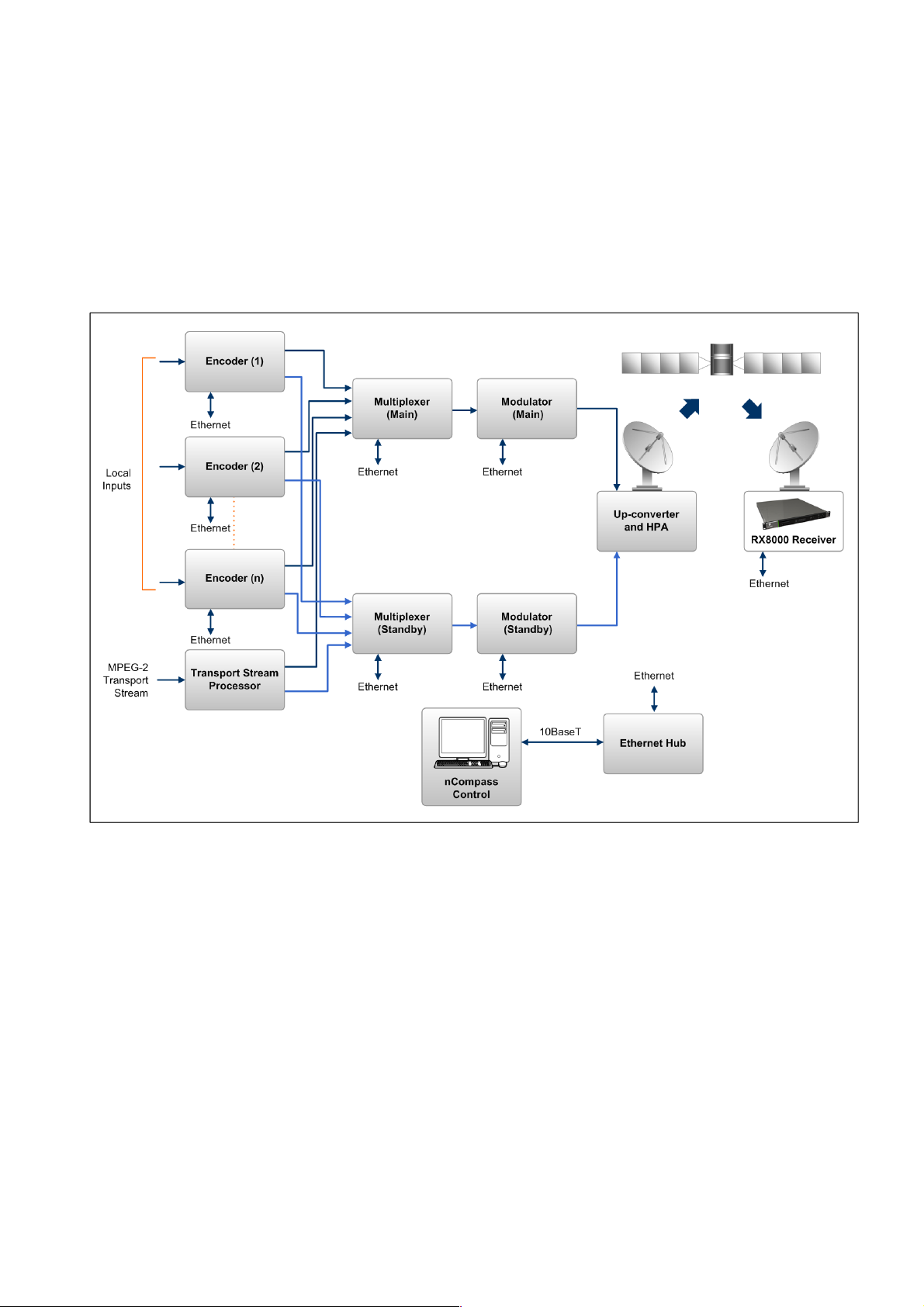
1.3.1 Typical Satellite System
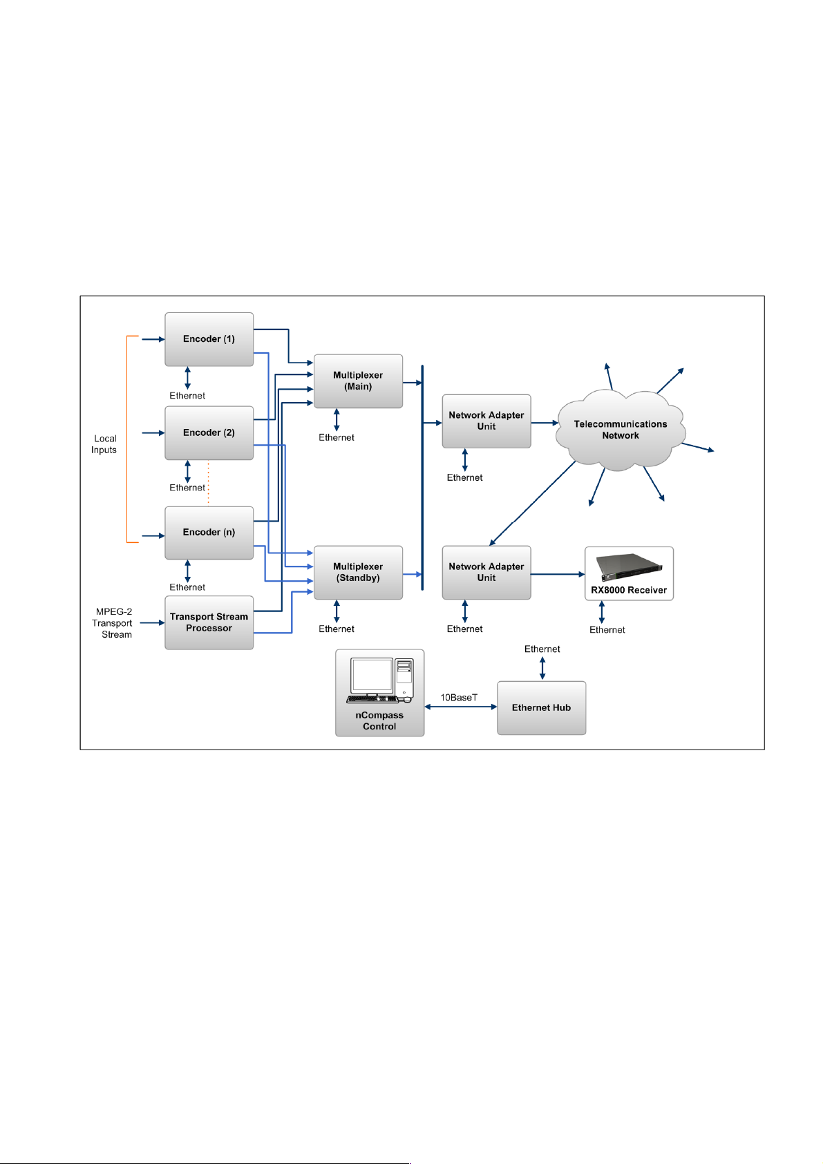
The RX8000 Series Receiver is a component of the MPEG-4 AVC/ MPEG-2/DVB
compliant range of Ericsson equipment. They are designed for use by broadcasters
and distributors of video, audio and data Services over satellite.
Figure 1.1 Typical Satellite Compression System
1.3.2 Input Connections
The Satellite Receiver interfaces directly to a Low-Noise Block (LNB) and accepts
an intermediate frequency (IF) input in the band 950 - 2150 MHz (L-band) for
operation in the specified symbol-rate range (see Annex B, Technical Specification).
The unit can provide DC power and polarization switching to the LNB.
EN/LZT 790 0005 R1A
1-17
Chapter 1
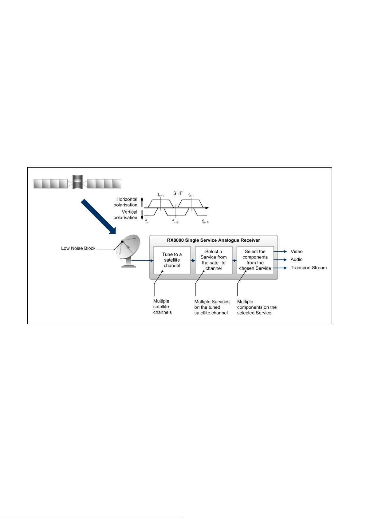
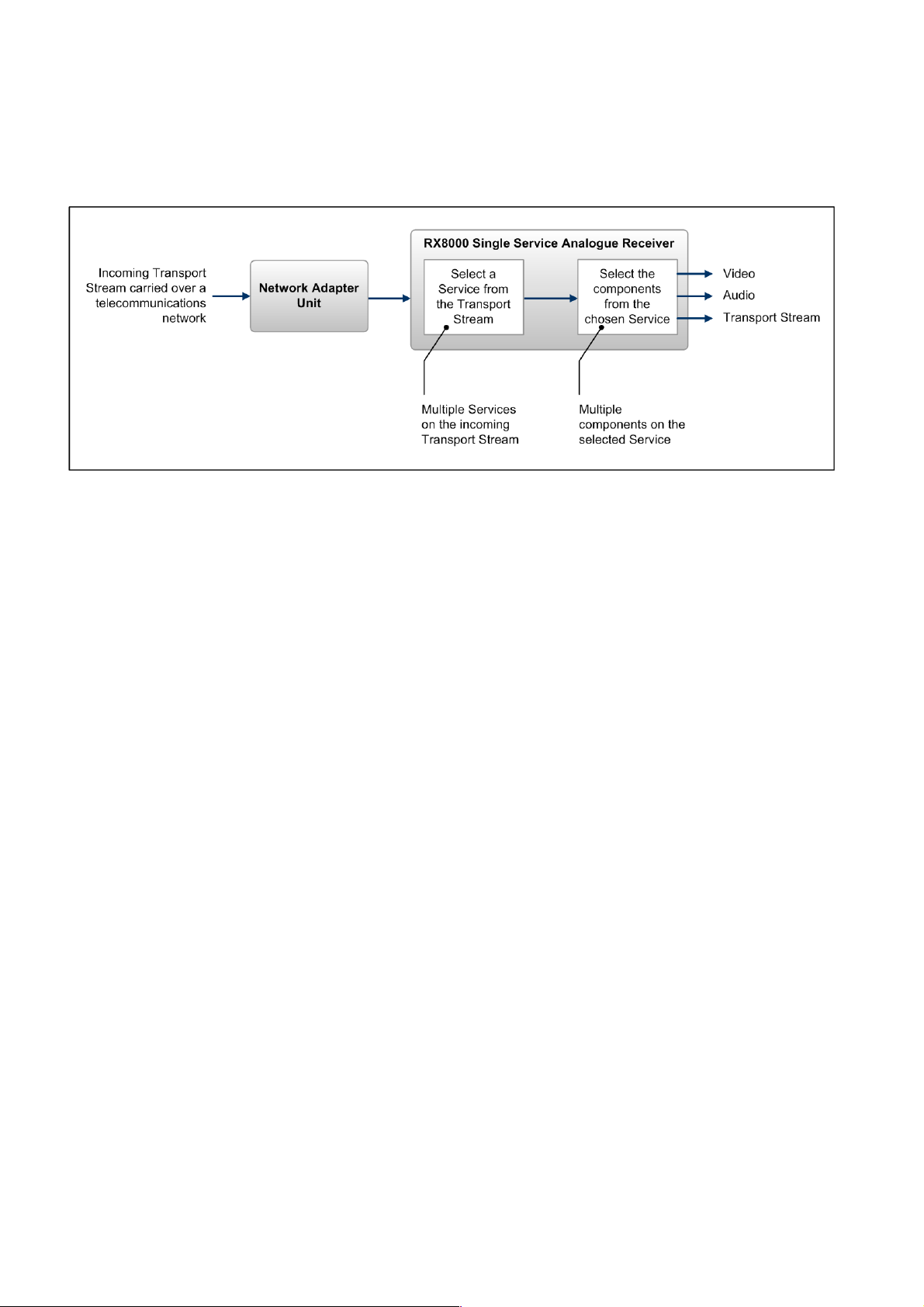
1.3.3 What the Satellite Receiver Does
The Receiver can be tuned to a specified satellite channel frequency and
polarization. The input is down-converted via a Low-Noise Block (LNB) to provide an
L-band input to the Receiver. The front-end tuning is microprocessor controlled with
a frequency synthesized local oscillator. A software tuning and acquisition algorithm
resolves translation errors (mainly due to the LNB).
The signal is then passed to a demodulator that recovers the signal using softdecision decoding. The resulting stream is Reed-Solomon decoded and
descrambled to provide inputs to the Decoder circuit. The received channel may
contain multiple Services, therefore the Receiver’s demultiplexer is configured to
select a single video Service and other audio/data components and present them at
the output.
Figure 1.2 What the Satellite Receiver Does
1-18
EN/LZT 790 0005 R1A
Chapter 1
1.4 The Telco Receiver/Decoder
1.4.1 Typical Decoder System
The Decoder is a component of Ericsson range of equipment. It is designed for use
by broadcasters and distributors of video and audio Services. It can be used as a
Transport Stream monitor or to decode signals received over a telecommunications
network.
Figure 1.3 Typical Compression System
1.4.2 What the Decoder Does
The G.703, ASI or IP interface is used to present the Transport Stream in the format
required by the internal Decoder circuitry. At this point, the operation of the unit is
the same as the Satellite Receiver.
The Decoder can be used to receive an input signal from a Public Telecom Network
via a Network Adapter Unit (NAU) or directly via G.703. No error correction is
supported at the input of the unit so a level of Quality of Service should be
negotiated with the Telecom Network Provider.
EN/LZT 790 0005 R1A
1-19
Chapter 1
The Decoder is configured to select a single video Service and other audio/data
components from the multiple Services on the incoming Transport Stream and
present them at the output.
Figure 1.4 Role of the Decoder
Note: G.703 input may also be used to interface to telco infrastructure.
1.5 Construction
The RX8000 Receiver is constructed using a screened self-ventilated modular
system. All operational inputs and outputs are via rear-panel connectors. The unit
may be operated freestanding or mounted in a 19-inch rack.
1.6 Front Panel
The user interface for the Front Panel consists of an alphanumeric Liquid Crystal
Display, pushbuttons, and a status LED that are used to set-up, control and monitor
the unit.
Various menu screens can be navigated on the LCD using the pushbuttons, which
allow you to select and modify key parameters and features of the unit.
Full details of the front panel menus and information on the use of these controls is
given in Chapter 3, Front Panel Control.
1-20
EN/LZT 790 0005 R1A
Chapter 1
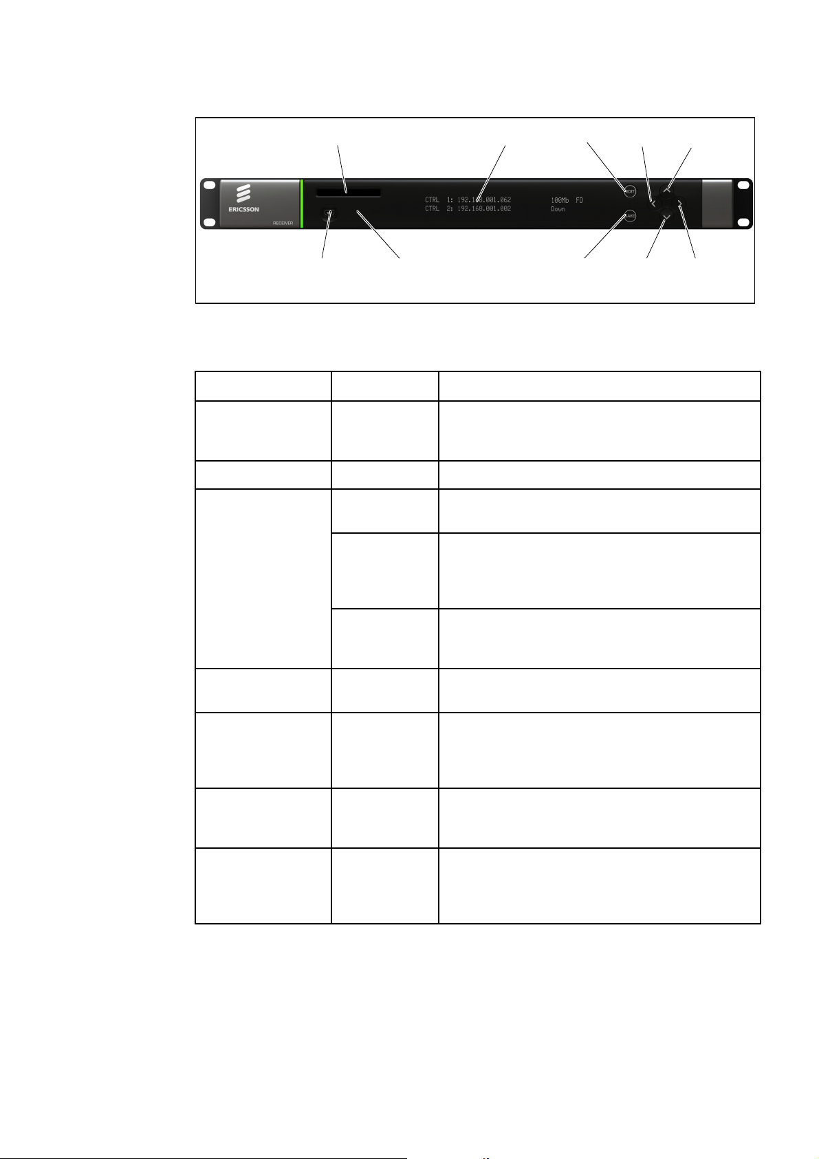
USB Connector
(Servicing Onl y)
CA SLOT
Status LED
LCD
EDIT
SAVE DOWN RIGHT
LEFT UP
Figure 1.5 Front Panel Controls (RX8200)
Table 1.12 Front Panel Controls
Item Color Description
CA Slot -
USB Connector - This connector is for factory / service use only.
Status LED
Red
Conditional Access Slot. Located on front panel of
RX8200 and rear panel of RX8310, RX8315 and
RX8330.
CRITICAL Error. Indicates that the unit has lost
lock with the Transport Stream.
Amber
Green
LCD -
Edit -
Save -
S Up
-
T Down
W Left (Back)
X Right (Forward)
MAJOR or MINOR Error. Indicates that the unit is
locked to a Transport Stream but an error has
been detected signifying incorrect conditions or
system functioning.
NO Errors. Indicates that the unit is locked to a
Transport Stream and correct conditions and
system functioning are detected.
2-line x 40-character back-lit dot-matrix Liquid
Crystal Display (LCD).
This pushbutton enables you to edit the
parameters on the selected LCD menu. Press
again to exit without saving any changes. Integral
LED lit when functional.
This pushbutton enables you to save any modified
parameters on the selected LCD menu. Integral
LED lit when functional.
Navigation pushbuttons for selecting relevant LCD
menu or for incrementing / decrementing selected
parameter values. Integral LED lit when
functional.
EN/LZT 790 0005 R1A
1-21
Chapter 1
A
A
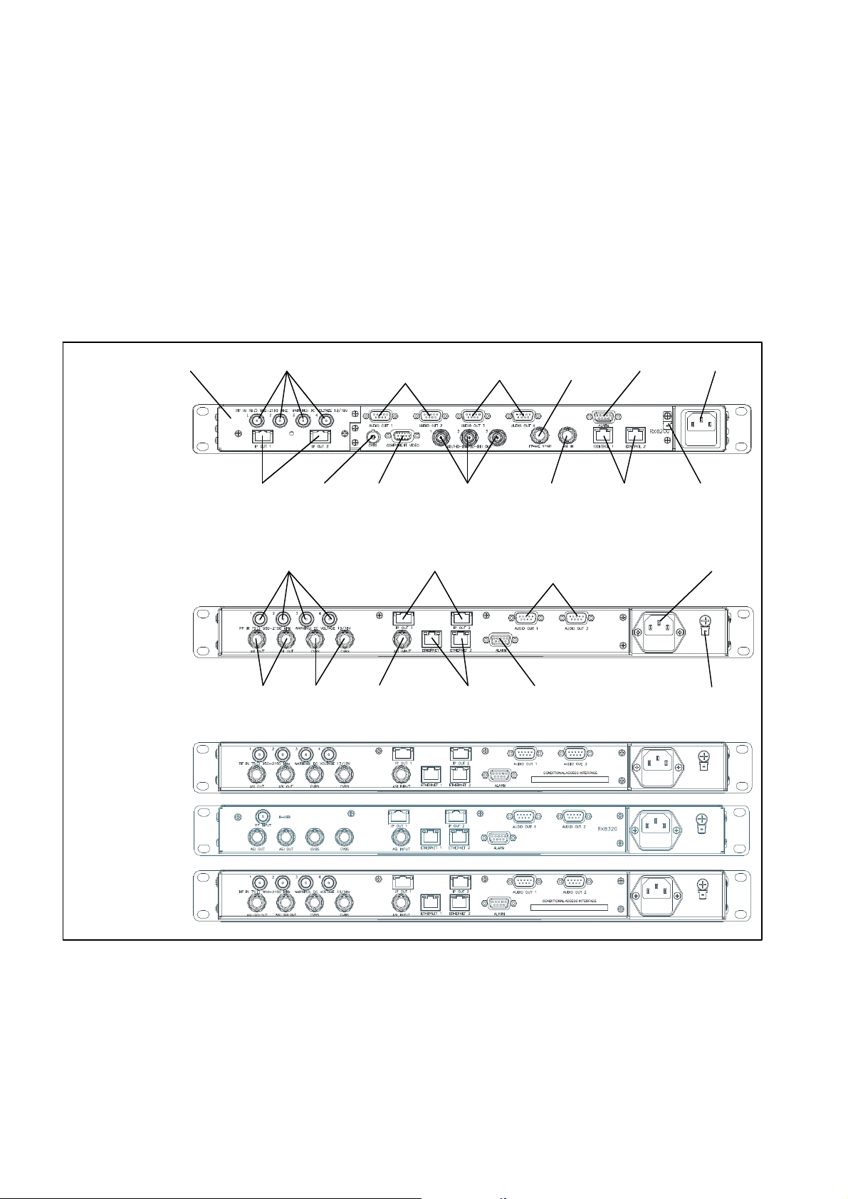
1.7 Rear Panels
All inputs, outputs and control connections are taken via the rear panel. Due to the
modular nature of these units, factory fitted hardware modules with different
connections can be fitted to any unit and therefore only a typical (sample) rear panel
images are shown below.
Full details of the connectors for ALL base models and options are given in
Chapter 2, Installing the Equipment.
Full details of all the options are given in Chapter 6, Options.
RX8200
Sample configuration
with: Satellite input,
frame sync, HD video
output, IP Transport
Stream output and 2x
Audio output modules
installed.
RX8310
RX8315
INPUT MODULE
RF IN 1-4
IP OUT 1-2
ASI OUT 1-2 CVBS
CVBS
RF IN 1-4 AUDIO OUT (1)
AUDIO OUT (1)
1-2
COMPONENT
VIDEO
ASI/HD-SDI/SD-
SDI OUT 1-3
IP OUT 1-2
ETHERNET 1-2
AUDIO OUT (2)
3-4
SI INPUT
LARM ASI INPUT
FRAME
SYNC
1-2
ALARM
CONTROL
1-2
AC POWER
TECHNICAL
EARTH
AC POWER
TECHNICAL
EARTH
RX8320
RX8330
Figure 1.6 Rear Panels (RX8200, RX8310, RX8315, RX8320 and RX8330)
1-22
EN/LZT 790 0005 R1A

Chapter 1
Table 1.13 Rear Panels
Item Type Description
RF IN 1-4
ASI OUT 1-2
F-type 75 Ω
BNC 75 Ω
ASI/SDI OUT
ASI/HD-SDI/SD-SDI
OUT
CVBS
ASI INPUT
BNC 75 Ω
BNC 75 Ω
SVGA OUTPUT 15-way D-type
IP OUT 1-2 RJ-45
ETHERNET 1-2
RJ-45
CONTROL 1-2
ALARM
9-way D-type
ALARM RELAY
Radio Frequency (L-band) input.
ASI = Asynchronous Serial Interface.
SDI = Synchronous Data Interface.
SD-SDI = Standard Definition SDI.
HS- SDI = High Definition SDI.
Composite Video output.
Asynchronous Serial Interface input.
Streaming data format which carries the
MPEG Transport Stream.
Component Video output (RGB/HV (SVGA) or
YPrPb).
IP Output card supports 1000BaseT Ethernet
transmission of encapsulated transport stream
Gigabit IP data / feed output on dual redundant
connectors.
A summary ALARM relay provides contact
closure when the unit detects an alarm, or the
power is switched off.
AUDIO OUT 1-2 9-way D-type
Each connector carries a single channel of a
stereo pair in both analogue and balanced
digital form.
CA INTERFACE Card Slot
A single slot allows the insertion of a Smart
Card for the use of Common Interface Support.
AC POWER IEC 100-240 V AC power input.
TECHNICAL EARTH
Spade
Unit earthing connector.
terminal
EN/LZT 790 0005 R1A
1-23

Chapter 1
BLANK
1-24
EN/LZT 790 0005 R1A

2 Installing the Equipment
Chapter 2
Contents
2.1 Read This First! ....................................................................................2-3
2.1.1 Handling ...............................................................................................2-3
2.1.2 Installing the Equipment .......................................................................2-3
2.1.3 Lifting ....................................................................................................2-3
2.1.4 Site Requirements ................................................................................ 2-3
2.1.4.1 Power Supplies..................................................................................... 2-3
2.1.4.2 Environment .........................................................................................2-3
2.1.4.3 Lightning Protection.............................................................................. 2-3
2.2 Preliminary Checks............................................................................... 2-4
2.2.1 Mechanical Inspection .......................................................................... 2-4
2.2.2 Moving the Equipment Safely............................................................... 2-4
2.3 Installing the Equipment .......................................................................2-4
2.3.1 Fixing .................................................................................................... 2-4
2.3.2 Ventilation............................................................................................. 2-5
2.3.2.1 Openings in the Covers ........................................................................ 2-5
2.3.2.2 Care in Positioning ...............................................................................2-5
2.3.2.3 Protection from Moisture ......................................................................2-5
2.3.3 Installing Cables - Safety...................................................................... 2-6
2.4 EMC Compliance Statements .............................................................. 2-6
2.4.1 EN 55022/AS/NZS 3548....................................................................... 2-6
2.4.2 FCC ......................................................................................................2-6
2.5 AC Supply Operating Voltage and Fusing – Safety Information........... 2-6
2.5.1 AC Power Supply .................................................................................2-6
2.5.2 AC Power Supply Cord......................................................................... 2-7
2.5.2.1 General................................................................................................. 2-7
2.5.2.2 Wire Colors........................................................................................... 2-7
2.5.3 Connecting the Equipment to the AC Power Supply ............................ 2-8
2.6 Protective Earth/Technical Earth ..........................................................2-8
2.7 Signal Connections............................................................................... 2-9
2.7.1 General................................................................................................. 2-9
2.7.2 RF IN Connector (RX8200 and RX8320 only).................................... 2-10
2.7.3 ASI OUT Connector (RX8310/15/20 only).......................................... 2-11
2.7.4 ASI/SDI OUT Connector (RX8200 and RX8330 only)........................ 2-12
2.7.5 ASI/HD-SDI/SD-SDI OUT Connector (RX8200 only) ......................... 2-12
2.7.6 CVBS Connector ................................................................................2-12
2.7.7 AUDIO/AUDIO OUT Connector.......................................................... 2-13
2.7.8 ETHERNET/CONTROL Connector .................................................... 2-13
EN/LZT 790 0005 R1A
2-1

Chapter 2
2.7.9 ASI IN Connector ............................................................................... 2-14
2.7.10 COMPONENT VIDEO Connector (RX8200 only) .............................. 2-14
2.7.11 DATA OUT Connector........................................................................ 2-15
2.7.12 ALARM Connector ............................................................................. 2-15
2.7.13 RS232/RS485 REMOTE Connector .................................................. 2-16
List of Figures
Figure 2.1
Air-Flow Through the Equipment.......................................................... 2-5
Figure 2.2 AC Power Inlet Assembly..................................................................... 2-7
Figure 2.3 Location of the Technical Earth on RX8200......................................... 2-9
Figure 2.4 Location of the Technical Earth on RX83XX........................................ 2-9
Figure 2.5 Rear Panels (RX8200, RX8310, RX8315, RX8320 and RX8330) ..... 2-10
List of Tables
Table 2.1
Supply Cord Wiring Colors................................................................... 2-8
Table 2.2 Non Standard Supply Cord Wire Colors............................................... 2-8
Table 2.3 RF IN Connector ................................................................................ 2-11
Table 2.4 ASI OUT Connector ........................................................................... 2-11
Table 2.5 ASI/SDI OUT Connector .................................................................... 2-12
Table 2.6 ASI/HD-SDI/SD-SDI OUT Connector................................................. 2-12
Table 2.7 CVBS Connector................................................................................ 2-12
Table 2.8 AUDIO/AUDIO OUT Connectors........................................................ 2-13
Table 2.9 ETHERNET/CONTROL Connectors.................................................. 2-13
Table 2.10 ASI IN Connector ............................................................................... 2-14
Table 2.11 COMPONENT VIDEO Connector ...................................................... 2-14
Table 2.12 DATA OUT Connector........................................................................ 2-15
Table 2.13 ALARM Connector ............................................................................. 2-15
Table 2.14 RS232/RS485 REMOTE Connector .................................................. 2-16
2-2
EN/LZT 790 0005 R1A

Chapter 2
2.1 Read This First!
2.1.1 Handling
The equipment must be handled and installed carefully and thoughtfully to prevent
safety hazards and damage.
2.1.2 Installing the Equipment
Ensure the personnel designated to fit the unit have the appropriate skills and
knowledge. If in any doubt, contact Ericsson Customer Services (see Preliminary
Pages for contact details).
Installation of the product should follow these instructions, and should only use
installation accessories recommended by the manufacturers. When rack mounted,
this equipment must have shelf supports as well as being fixed at the front panel.
Do not use this product as a support for any other equipment.
2.1.3 Lifting
In some circumstances the unit might be awkward to lift. In which case, do not
attempt to lift or move it without proper assistance or equipment. If in doubt, seek
assistance.
2.1.4 Site Requirements
2.1.4.1 Power Supplies
See Annex B, Technical Specification for a full specification.
2.1.4.2 Environment
See Annex B, Technical Specification for a full specification.
Do not install this product in areas of high humidity or where there is danger of water
ingress.
2.1.4.3 Lightning Protection
If the receiver has been subject to a lightning strike or power surge which has
stopped it working, disconnect the power immediately. Do not re-apply power until it
has been checked for safety. If in doubt, contact Ericsson Customer Services.
EN/LZT 790 0005 R1A
Warning!
2-3

Chapter 2
Where appropriate, ensure this product has an adequate level of lightning
protection. Alternatively, during a lightning storm or when it is left unattended and
unused for long periods of time, unplug it from the supply outlet and disconnect the
output equipment. This prevents damage to the product due to lightning and power
line surges.
2.2 Preliminary Checks
2.2.1 Mechanical Inspection
When taking delivery of a RX8000 Series Receiver check the equipment items
delivered against the enclosed delivery note. Inspect the equipment for damage in
transit. If in doubt, contact Ericsson Customer Services (see Preliminary Pages).
Note: Do not remove the covers of this equipment as doing so may invalidate any
warranties, cause a safety hazard and/or affect the EMC performance. It
may also invalidate any safety tests. Check with Ericsson Customer
Services beforehand.
2.2.2 Moving the Equipment Safely
Do not place this product on an unstable cart, stand, bracket, or
table. The product may fall, causing serious injury and serious
damage to the product. Use only with a cart, stand, bracket or
table recommended by Ericsson.
An appliance and cart combination should be moved with care. Quick stops,
excessive force, and uneven surfaces may cause the appliance and cart
combination to overturn. Do not move or carry the equipment whilst it is still
connected to the supply or other leads, is live, or is in operation.
2.3 Installing the Equipment
2.3.1 Fixing
The equipment is designed for fixed use only and has been shipped with fixing
brackets suitable for a standard 19-inch rack. When installed in a rack, it should be
secured using the fixing brackets. In addition, support shelves must be used to
reduce the weight on the brackets. Ensure it is firmly and safely located and it has
an adequate flow of free-air.
2-4
Slide the receiver onto the chassis supports and affix to the rack by means of an
M6 x 18 mm panhead screw in each corner.
A freestanding unit should be installed on a secure horizontal surface where it is
unlikely to be knocked or its connectors and leads disturbed.
EN/LZT 790 0005 R1A

Chapter 2
2.3.2 Ventilation
2.3.2.1 Openings in the Covers
Side openings in the unit, as well as side-mounted cooling fans, are provided for
ventilation. They ensure reliable operation of the product and protect it from
overheating. The openings of the fans must not be blocked or covered.
Fans are
mounted on
this side of
the unit
Air is released
through vents
at the side of
the unit.
Figure 2.1 Air-Flow Through the Equipment
2.3.2.2 Care in Positioning
The fans contained within this unit are not fitted with a dust/insect filter. Pay
attention to the environment in which it is to be used.
Do not install units so that the air intake of one aligns with the outlet on another.
Provide baffles and adequate spacing.
The equipment should never be placed near or over a radiator or other source of heat.
It should not be placed in a built-in installation such as a rack unless proper ventilation
is provided and the instructions have been adhered to.
Allow at least 40 mm free air-space at each side of the equipment to ensure
adequate cooling. Racks containing stacked equipment may need to be forced aircooled to reduce the ambient temperature within the rack.
Cautions!
2.3.2.3 Protection from Moisture
Do not install this equipment in areas of high humidity or where there is a danger of
water ingress.
EN/LZT 790 0005 R1A
2-5

Chapter 2
2.3.3 Installing Cables - Safety
Power supply cables should be routed so that they are not likely to be walked on or
pinched by items placed upon or against them. Pay particular attention to cables at
plugs, convenience receptacles, and the point where they exit from the appliance.
Do not run AC power cables in the same duct as signal leads. Do not move or install
equipment whilst it is still attached to the mains supply. Ensure safety and ESD
precautions are observed whilst inter-connecting equipment.
2.4 EMC Compliance Statements1
2.4.1 EN 55022/AS/NZS 3548
This is a Class A product. In a domestic environment this product may cause radio
interference in which case the User may be required to take adequate measures.
2.4.2 FCC
This equipment has been tested and found to comply with the limits for a Class A
digital device, pursuant to Part 15 of the FCC Rules. These limits are designed to
provide reasonable protection against harmful interference when the equipment is
operated in a commercial environment.
This equipment generates, uses and can radiate radio frequency energy and, if not
installed and used in accordance with the Reference Guide, may cause harmful
interference to radio communications. Operation of this equipment in a residential
area is likely to cause harmful interference in which case the User will be required to
correct the interference at ones own expense.
2.5 AC Supply Operating Voltage and Fusing – Safety Information
2.5.1 AC Power Supply
The equipment operates from an wide-ranging mains power supply (100-240 V AC
50/60 Hz nominal) and is designed for use in ambient air temperature in the range
0°C to +50°C. There are no links etc. to be altered for operation from different
supply voltages. The full Technical Specification is given in Annex B, Technical
Specification.
1
The EMC information was correct at the time of manufacture.
2-6
EN/LZT 790 0005 R1A

Chapter 2
Warnings!
The RX8000 series receivers should only be operated from the type of power source
indicated on the marking label. If you are not sure of the type to your business,
consult your appliance dealer or local power company. Do not overload wall outlets
and extension cords as this can result in a risk of fire or electric shock.
The RX8000 series receivers are NOT fitted with an AC power ON/OFF switch.
Ensure the supply socket outlet is installed or located near the equipment so that it
is accessible.
Supply Mains Inlet
Fuse Carrier
Figure 2.2 AC Power Inlet Assembly
Note: See Annex B, Technical Specification for fuse information.
2.5.2 AC Power Supply Cord
2.5.2.1 General
A two-meter mains supply cord is supplied with this product. It is fitted with a molded
plug suitable for the USA, UK or mainland Europe as advised at the time of ordering.
Note: The equipment is not fitted with an AC power supply ON/OFF switch.
Ensure the socket-outlet supplying the equipment is installed near the
equipment so that it is easily accessible.
2.5.2.2 Wire Colors
The wires in the supply cord are colored as shown in Table 2.1.
EN/LZT 790 0005 R1A
2-7

Chapter 2
Table 2.1 Supply Cord Wiring Colors
UK
(BS 1363)
Earth: Green-and-yellow Green-and-yellow Green
Neutral: Blue Blue White
Live: Brown Brown Black
EUROPE
(CEE 7/7)
USA
(NEMA 5-15P)
If the colors do not correspond with the colored markings identifying the terminals in
a locally supplied plug, proceed as in Annex B. The inclusion of Table 2.2 is for
reference.
Table 2.2 Non Standard Supply Cord Wire Colors
Wire Color (UK) Action
green-and-yellow
blue
brown
...must be connected to the terminal in the plug which is marked
with the letter E or the safety earth symbol or colored green or
green-and-yellow.
...must be connected to the terminal in the plug which is marked
with the letter N or colored black.
...must be connected to the terminal in the plug which is marked
with the letter L or colored red.
2.5.3 Connecting the Equipment to the AC Power Supply
As there is no mains power switch fitted to this unit, ensure the local AC power
supply is switched OFF before connecting the supply cord. Connect the mains lead
to the equipment and then to the local supply.
2.6 Protective Earth/Technical Earth
Warnings!
This unit must be correctly earthed through the molded plug supplied; if the local
mains supply does not have an earth conductor do not connect the unit. Contact
Ericsson Customer Services for advice.
Before connecting the unit to the supply, check the supply requirements in Annex B.
The terminal marked at the rear panel is a Technical Earth. Its use is
recommended. This is NOT a protective earth for electric shock protection. The
terminal is provided to:
1. Ensure all equipment chassis fixed within a rack are at the same technical earth
potential.
2-8
EN/LZT 790 0005 R1A

Chapter 2
2. Eliminate the migration of stray charges when connecting between equipment.
To do this, connect a wire between the Technical Earth terminal and a suitable
point on the rack.
The Technical Earth provides a suitable connection between the equipment and the
installation to give a low impedance path at normal operating frequencies.
Technical Earth
Figure 2.3 Location of the Technical Earth on RX8200
Figure 2.4 Location of the Technical Earth on RX83XX
2.7 Signal Connections
2.7.1 General
Technical Earth
It is strongly recommended that the terminal marked at the rear panel of the
equipment is connected to a site Technical Earth before any external connections
are made and the equipment is powered. This limits the migration of stray charges.
EN/LZT 790 0005 R1A
Caution!
2-9

Chapter 2
A
A
All signal connections are made via the rear panel. A typical rear panel is shown in
Figure 2.5. Full technical specifications for the connections are given in Annex B.
The Receiver provides a flexible Transport Stream input interface. The status
information appropriate to each input type is available to the User via the User
Interface, and also via the remote control interfaces.
RX8200
Sample configuration
with: Satellite input,
frame sync, HD video
output, IP Transport
Stream output and 2x
Audio output modules
installed.
RX8310
RX8315
INPUT MODULE
RF IN 1-4
IP OUT 1-2
ASI OUT 1-2 CVBS
CVBS
RF IN 1-4 AUDIO OUT (1)
AUDIO OUT (1)
1-2
COMPONENT
VIDEO
ASI/HD-SDI/SD-
SDI OUT 1-3
IP OUT 1-2
ETHERNET 1-2
AUDIO OUT (2)
3-4
SI INPUT
LARM ASI INPUT
FRAME
SYNC
1-2
ALARM
CONTROL
1-2
AC POWER
TECHNICAL
EARTH
AC POWER
TECHNICAL
EARTH
RX8320
RX8330
Figure 2.5 Rear Panels (RX8200, RX8310, RX8315, RX8320 and RX8330)
2.7.2 RF IN Connector (RX8200 and RX8320 only)
Up to four RF inputs connect the L-band output of a
suitable Low-Noise Block down-converter (LNB) to the
unit either directly or via a suitable attenuator.
The RF inputs may also be used to supply DC power to
the LNB, if required.
RF IN 1/2/3/4
2-10
EN/LZT 790 0005 R1A

Chapter 2
Cautions!
The receiver provides DC power (see Chapter 3, Front Panel Control for details of
menu option) via the active L-band input connector to drive an LNB. Do not connect
equipment other than an LNB to this connector. Failure to do this may result in
damage to the external equipment.
The F-type connector is not suitable for repeated connection and disconnection.
When intended for use in this way, fit a sacrificial connector and connect to it.
Table 2.3 RF IN Connector
Item Specification
Connector type F-type 75 Ω female socket
Connector designation RF IN 1
RF IN 2
RF IN 3
RF IN 4
LNB Power Supply See Cautions! above.
Pin-outs Centre
Shield
Input
Ground/Chassis
2.7.3 ASI OUT Connector (RX8310/15/20 only)
The unit provides two coaxial ASI digital outputs
depending on the user selectable configuration.
Table 2.4 ASI OUT Connector
Item Specification
Connector type BNC 75 Ω female socket
Connector designation ASI OUT 1
ASI OUT 2
Pin-outs Centre
Shield
Output
Ground/Chassis
ASI OUT
EN/LZT 790 0005 R1A
2-11

Chapter 2
2.7.4 ASI/SDI OUT Connector (RX8200 and RX8330 only)
The unit provides two coaxial ASI/SDI outputs depending
on the user selectable configuration.
Table 2.5 ASI/SDI OUT Connector
Item Specification
Connector type BNC 75 Ω female socket
Connector designation ASI OUT 1
ASI OUT 2
Pin-outs Centre
Shield
Output
Ground/Chassis
2.7.5 ASI/HD-SDI/SD-SDI OUT Connector (RX8200 only)
The unit provides three coaxial ASI/HD-SDI/SD-SDI
outputs depending on the user selectable configuration.
Table 2.6 ASI/HD-SDI/SD-SDI OUT Connector
Item Specification
Connector type BNC 75 Ω female socket
Connector designation ASI/HD-SDI/SD-SDI OUT 1
ASI/HD-SDI/SD-SDI OUT 2
ASI/HD-SDI/SD-SDI OUT 3
ASI/SDI OUT
ASI/HD-SDI/SD-SDI OUT
Pin-outs Centre
Shield
2.7.6 CVBS Connector
A coaxial socket provides composite video outputs
supporting NTSC(M) (with and without pedestal) and
PAL(B,D,H,I,M).
Table 2.7 CVBS Connector
Item Specification
Connector type BNC 75 Ω female socket
Connector designation CVBS 1 (RX8200/RX300)
Pin-outs Centre
Shield
Output
Ground/Chassis
CVBS
CVBS 2 (RX8300 only)
Output
Ground/Chassis
2-12
EN/LZT 790 0005 R1A

Chapter 2
2.7.7 AUDIO/AUDIO OUT Connector
All units provide a pair of connectors supplying two
stereo channels. Each carries a single channel stereo
pair in both analogue and balanced digital form.
Table 2.8 AUDIO/AUDIO OUT Connectors
Item Specification
Connector type 9-way, D-type, male
Connector designations AUDIO OUT 1
AUDIO OUT 2
AUDIO 3 (RX8200 only)
AUDIO 4 (RX8200 only)
Pin-outs
Nominal output impedance
Maximum data rate 3.072 Mbps
Analogue Output level
Pin 1 – Digital audio +
Pin 2 – Ground
Pin 3 – Left +
Pin 4 – Right +
Pin 5 – Ground
Pin 6 – Digital audio –
Pin 7 – Ground
Pin 8 – Left –
Pin 9 – Right –
50 Ω
+20 dBm nominal clipping
level. Selectable in range 12
to +24 dBm.
AUDIO/AUDIO OUT
Load impedance
≥600 Ω balanced
2.7.8 ETHERNET/CONTROL Connector
All units provide two Ethernet remote control interfaces
for Web Browser Control.
Table 2.9 ETHERNET/CONTROL Connectors
Item Specification
Connector type RJ-45 (100BaseT)
Connector designation ETHERNET 1 or CONTROL 1
ETHERNET 2 or CONTROL 2
Pin-outs
(Unused pins not
connected)
Pin 1 – Tx Out (+)
Pin 2 – Tx Out (-)
Pin 3 – Rx In (+)
Pin 6 – Rx In (-)
ETHERNET/CONTROL
EN/LZT 790 0005 R1A
2-13

Chapter 2
2.7.9 ASI IN Connector
All units provide an ASI input socket for detection of the
transport stream lock on the ASI input.
Table 2.10 ASI IN Connector
Item Specification
Connector type BNC 75 Ω female socket
Connector designation ASI IN
Pin-outs Centre
Shield
Input
Ground/Chassis
2.7.10 COMPONENT VIDEO Connector (RX8200 only)
The equipment is equipped with a SVGA 15-pin D-type
connector for video output monitoring in the standard
configuration.
The SVGA connector shall be set to RGB/HV (SVGA) or
YPrPb under control of the User interface and remote
control interfaces.
Table 2.11 COMPONENT VIDEO Connector
Item Specification
Connector type 15-way D-type, female
ASI IN
COMPONENT VIDEO
Connector designation COMPONENT VIDEO
Pin-outs
Pin 1 – Red / Pr, 75 Ω, 0,7Vt-t
Pin 2 – Green / Y, 75 Ω, 0,7Vt-t
Pin 3 – Blue / Pb, 75 Ω, 0,7Vt-t
Pin 4 – NC
Pin 5 – Video GND
Pin 6 – Red GND
Pin 7 – Green GND
Pin 8 – Blue GND
Pin 9 – NC
Pin 10 – Sync GND
Pin 11 – NC
Pin 12 – NC
Pin 13 – H-Sync
Pin 14 – V-Sync
Pin 15 – NC
2-14
EN/LZT 790 0005 R1A

Chapter 2
2.7.11 DATA OUT Connector
A data output interface may be used with either RS232 or
RS422 connector, as described below.
Table 2.12 DATA OUT Connector
Item Specification
Connector type 9-way, D-type, female
Connector designation DATA OUT
Pin RS232 RS422
DATA OUT
Pin-outs Pin 1
2.7.12 ALARM Connector
All units provide an alarm relay connector supplying a
summary relay. Under user configuration, it is activated
whenever the unit detects an alarm, or the power is
switched off.
Table 2.13 ALARM Connector
Item Specification
Connector type 9-way, D-type, female
Connector designation ALARM
Pin 2
Pin 3
Pin 4
Pin 5
Pin 6
Pin 7
Pin 8
Pin 9
NC
TxD
RxD
NC
NC
NC
CTS
(RTS)
NC
HSD_CLK_A
NC
NC
NC
NC
HSD_CLK_B
NC
HSD_DATA_A
HSD_DATA_B
ALARM RELAY
Pin-outs Pin 1 – Relay 1, Normally Closed
Pin 2 – Relay 2, Common
Pin 3 – Relay 1, Common
Pin 4 – Relay 3, Common
Pin 5 – Relay 1, Normally Open
Pin 6 – Relay 2, Normally Closed
Pin 7 – Relay 2, Normally Open
Pin 8 – Relay 3, Normally Closed
Pin 9 – Relay 3, Normally Open
EN/LZT 790 0005 R1A
2-15

Chapter 2
2.7.13 RS232/RS485 REMOTE Connector
A remote control interface may be used with either RS232
or RS485 connector, as detailed below.
Table 2.14 RS232/RS485 REMOTE Connector
Item Specification
Connector type 9-way, D-type, male
Connector designation RS232/RS485 REMOTE
Pin RS232 RS485
RS232/RS485 REMOTE
Pin-outs Pin 1
Pin 2
Pin 3
Pin 4
Pin 5
Pin 6
Pin 7
Pin 8
Pin 9
DCD
RxD
TxD
DTR
Ground
DSR
RTS
CTS
RI
NC
NC
NC
RxD
NC
TxDTxD+
RXDNC
2-16
EN/LZT 790 0005 R1A

3 Front Panel Control
Chapter 3
Contents
3.1 Introduction ...........................................................................................3-3
3.2 Powering the Equipment ...................................................................... 3-3
3.2.1 Switching On ........................................................................................3-3
3.2.2 Power Up Operating Modes .................................................................3-3
3.3 Using the Front Panel Controls ............................................................ 3-4
3.3.1 USB Connector..................................................................................... 3-5
3.3.2 Status LED ...........................................................................................3-5
3.3.3 LCD ......................................................................................................3-5
3.3.4 Arrow Pushbuttons (Up, Down, Left, Right).......................................... 3-6
3.3.5 Edit and Save Pushbuttons ..................................................................3-6
3.4 Example Configuration .........................................................................3-7
3.5 Front Panel Menus ...............................................................................3-8
3.5.1 1 System............................................................................................. 3-10
3.5.1.1 1.1 Network ........................................................................................3-10
3.5.1.2 1.2 Build.............................................................................................. 3-12
3.5.1.3 1.3 USN .............................................................................................. 3-14
3.5.1.4 1.4 Factory.......................................................................................... 3-14
3.5.1.5 1.5 Front Panel (FP) ........................................................................... 3-15
3.5.2 2 Input (Satellite Input Card RX8200/HWO/DVBS2) .......................... 3-16
3.5.2.1 2.1 Select/Primary Input .....................................................................3-16
3.5.2.2 2.2 Select Satellite Input..................................................................... 3-17
3.5.3 2 Input (I/P Input Card RX8XXX/HWO/IP/GIGE)................................ 3-22
3.5.3.1 2.1 Select/Primary Input .....................................................................3-22
3.5.3.2 2.2 IP Input Card ................................................................................3-23
3.5.4 2 Input (8VSB Input Card RX8320/HWO/8VSB) ................................3-38
3.5.4.1 2.1 Select/Primary Input .....................................................................3-38
3.5.4.2 2.2 8VSB ............................................................................................3-39
3.5.4.3 2.3 8VSB CTRL .................................................................................. 3-39
3.5.5 2 Input (G703 ATM Input Card RX8XXX/HWO/G703) .......................3-40
3.5.5.1 2.1 Select/Primary Input .....................................................................3-40
3.5.5.2 2.2 G703............................................................................................. 3-41
3.5.6 3 Service............................................................................................. 3-47
3.5.6.1 3.1 Decode Service ............................................................................3-47
3.5.6.2 3.2 Video ............................................................................................3-48
3.5.6.3 3.3 Audio ............................................................................................3-50
3.5.6.4 3.4 SDI Embedding ............................................................................3-51
3.5.7 4 CA Systems..................................................................................... 3-52
EN/LZT 790 0005 R1A
3-1

Chapter 3
3.5.7.1 4.1 Service Table ............................................................................... 3-52
3.5.7.2 4.2 Director......................................................................................... 3-53
3.5.8 5 Output ............................................................................................. 3-56
3.5.8.1 5.1 Output Selection........................................................................... 3-56
3.5.8.2 5.2 TS Feed Selection........................................................................ 3-57
3.5.9 6 Presets ............................................................................................ 3-58
3.5.9.1 6.1 Preset State ................................................................................. 3-58
3.5.9.2 6.2 Select/Save Presets..................................................................... 3-58
List of Figures
Figure 3.1
Power Up Operating Mode................................................................... 3-4
Figure 3.2 Front Panel Controls (RX8200)............................................................ 3-5
Figure 3.3 Front Panel Menus............................................................................... 3-8
Figure 3.4 Input Card Front Panel Menus ............................................................. 3-9
List of Tables
Table 3.1
Setting Up the DVB-S2 Satellite Receiver............................................ 3-7
3-2
EN/LZT 790 0005 R1A

Chapter 3
3.1 Introduction
This chapter describes the features and options provided by the Front Panel menus
for controlling the RX8000 Series Receivers locally.
3.2 Powering the Equipment
3.2.1 Switching On
Caution!
This equipment should not be operated unless the cooling fans are working and
there is free-air flow around the unit.
1. Connect all signal and power cables to the rear panel of the unit. All connectors
are described in Chapter 2, Installing the Equipment.
2. Switch on the AC power supply to the unit at the wall or rack outlet.
Note: The RX8000 Series Receivers do NOT contain a power on/off switch.
3. After a short period of initialization the following screen is displayed on the Front
Panel:
4.3.2 (Bank 0)
4. During initialization, confirm that the Status LED is on and all Up, Down, Left,
Right, Edit and Save pushbuttons are lit.
3.2.2 Power Up Operating Modes
When the equipment is switched on it will assume the control mode that was set
when the power was turned off. This could be either:
• Local Front Panel/Web Browser control
• Director NCP control.
See the following figure for an overview of the power up operating modes. he following figure for an overview of the power up operating modes.
INITIALIZING
EN/LZT 790 0005 R1A
3-3

Chapter 3
Figure 3.1 Power Up Operating Mode
3.3 Using the Front Panel Controls
The user interface for the Front Panel consists of an alphanumeric Liquid Crystal
Display, pushbuttons, and a status LED that are used to set-up, control and monitor
the unit.
Various menu screens can be navigated on the LCD using the pushbuttons, which
allow you to select and modify key parameters and features of the unit.
3-4
EN/LZT 790 0005 R1A

Chapter 3
CA SLOT
USB Connector
(Servicing Onl y)
Figure 3.2 Front Panel Controls (RX8200)
3.3.1 USB Connector
This connector is for factory / service use only.
3.3.2 Status LED
This multi-coloured LED provides a visual indication of the summary status of the
unit. The LED can be any one of three colours:
Status LED
LCD
EDIT
SAVE DOWN RIGHT
LEFT UP
• Red (CRITICAL Error). Indicates that the unit has lost lock with the Transport
Stream.
• Amber (MAJOR or MINOR Error). Indicates that the unit is locked to a
Transport Stream but an error has been detected signifying incorrect conditions
or system functioning.
• Green (NO Errors). Indicates that the unit is locked to a Transport Stream and
correct conditions and system functioning are detected.
3.3.3 LCD
A 2-line x 40-character back-lit dot-matrix Liquid Crystal Display (LCD) displays
various menus and settings. The menus and setting available will vary depending on
which receiver model is being used and which options have been enabled through
the purchase of a suitable license.
See Front Panel Menus on page 3-8 for details of all menus.
All menu is numbered to aid with navigation and are arranged in 6 main categories:
1. System: This menu includes user settings for: IP Control ports set-up, IP Control
ports link status, Unit Build version details, Unit Electronic Serial Number.
2. Input: This menu is dependent on which Hardware Input Card Option is fitted to
the unit: Satellite Input Card, I/P Input Card, G.703 Input Card or 8VSB Input
Card.
EN/LZT 790 0005 R1A
3-5

Chapter 3
3. Service: This menu includes user settings for the currently selected service for
decode from the incoming feed.
4. CA Systems: This menu includes user settings for: the currently selected
services for decryption from the incoming feed, Director parameters and status.
5. Output: This menu includes user settings for: Output selection, TS Feed
Selection.
6. Presets: This menu includes user settings for storing and retrieving of up to
40 sets of input parameters (tuning parameters and service selections).
3.3.4 Arrow Pushbuttons (Up, Down, Left, Right)
Four arrow pushbuttons (or keys) are used to navigate through the front panel LCD
menus.
Each arrow pushbutton is backlit by an integral LED when active, indicating that a
further choice or action is available by pressing that pushbutton.
S = Up
T = Down
W = Left (Back)
X = Right (Forward)
3.3.5 Edit and Save Pushbuttons
The Edit and Save pushbuttons are used to modify and store user settings within
the selected menu.
The Edit pushbutton is backlit by an integral LED when the current menu contains
an editable setting.
To edit a user setting within the selected menu:
1. Press the Edit pushbutton and then use the W (Back) and X (Forward)
pushbuttons to move the cursor within that menu (if necessary).
2. Change the value of the setting using the S (Up) and T (Down) pushbuttons.
3-6
During this edit operation, both the Edit and Save pushbuttons will be lit.
The Save pushbutton is backlit by an integral LED when changes have been made
to a setting that require saving.
When a user setting has been modified:
1. Press the Save pushbutton to confirm and action this new setting.
EN/LZT 790 0005 R1A

Chapter 3
2. To ignore any changes that have been made and to return to the original setting,
press the Edit pushbutton.
3.4 Example Configuration
The following example configuration uses the Front Panel menus to set up the
DVB-S2 Satellite Receiver (not available for RX8320) using Menu 2.
Table 3.1 Setting Up the DVB-S2 Satellite Receiver
Step Action Result
1 Go to Menu 2.2 and select RF INPUT 1.
2
3
4
5
6
7
8
Scroll to Menu 2.2.2.1.1. Enter the LNB
FREQUENCY then press Save.
Scroll to Menu 2.2.2.1.2. Enter the
SATELLITE FREQUENCY then press
Save.
Scroll to Menu 2.2.2.1.3. Enter the
SYMBOL RATE then press Save.
Scroll to Menu 2.2.2.1.4. Enter the DVB
Modulation Standard then press Save.
Scroll to Menu 2.2.2.1.5. Enter the
ROLL-OFF then press Save.
Scroll to Menu 2.2.2.1.7. Enter the
SEARCH RANGE then press Save.
Scroll to Menu 2.2.2.1.8. and 2.2.2.1.9.
Enter the LNB POWER and VOLTAGE
settings then press Save.
The Receiver can take its signals from four sources.
Set-up source 1.
This sets up the LNB frequency for the selected
Source in MHz.
This sets up the Satellite frequency for the selected
Source in MHz.
Sets the symbol rate for the selected Source in
Msymbol/s.
This sets up the DVB modulation Standard (DVB-S
or DVB-S2). FEC detection is automatic. In DVB-S2
mode the demodulator automatically detects and
locks to both QPSK and 8PSK constellations.
Sets the Roll-Off of the demodulator Root Nyquist
Filter. Choose between 35%, 25%, 20%. This value
should match that set in the transmitting modulator.
This sets up the centre frequency Search Range for
the selected Source in kHz.
Sets the LNB power for the selected Source
(ON, OFF). Also sets the LNB voltage settings
(18 V – Horiz, 13 V – Vert).
9
10 Repeat steps 2 through 9 for input 2 to 4
Scroll to Menu 2.2.2.1.10. Enter the LNB
22 kHz setting then press Save.
Enables or disables the LNB 22 kHz control tone for
the selected Source (On, Off).
EN/LZT 790 0005 R1A
3-7

Chapter 3
3.5 Front Panel Menus
An overview of the available Front Panel menus is shown in Figure 3.3. The menus
and settings available will vary depending on which receiver model is being used
and which options have been enabled through the purchase of a suitable license.
SWITCH ON
Boot Screen
INITIALIZING
4.3.2 (Bank 0)
Section 3.5.1
1. S ystem Menu
Section 3.5.2
2. Input Menu
Section 3.5.6
3. Service Menu
— 3.1 Decode Service
3.1.1 Service I
— 3.2 Video
3.2.1 Component Selection
3.2.2 User PID
3.2.3 User STD
3.2.4 Delay Mode
3.2.5 Rx Delay
— 3.3 Au di o
3.3.1 Audio 1
3.3.1.1 Component Selection
3.3.1.2 User PID
3.3.2-6 Audio 2-6 (as Audio 1)
3.4 SDI Embedding
3.4.1 CH 1+2: Embedding
3.4.2-3.4.8 CH3-16 Embedding (as CH 1+2)
— 1.1 Network Menu
— 1.2 Build Menu
— 1.3 Unit Serial Number
— 1.4 Factory Menu
— 1.5 FP (Front Panel) Menu
— 2.1 Select/Primary Input
— 2.2
See Figure 3.4
for Input Menus
1.1 N etwor k Men u
1.2 B uild M enu
1.4 Fa cto ry Me nu
1.5 FP (Front Panel) Menu
Section 3.5.1.1
— 1.1.1 IP1
— 1.1.2 MAC1
— 1.1.3 IP2
— 1.1.4 MAC2
— 1.1.5 Gateway
— 1.1.6 Status
Section 3.5.1.2
— 1.2.1 SW Version
— 1.2.2 PS Version
— 1.2.3 SD FPGA Version
— 1.2.4 HD FPGA Version
— 1.2.5 Audio DSP Version
— 1.2.6 TS FPGA Version
— 1.2.7 HW ID
— 1.2.8 422 FW
— 1.2.9 422 SW
Section 3.5.1.4
— 1.4.1 Reset All Exc IP & Reboot
— 1.4.2 Reset All Incl IP & Reboot
Section 3.5.1.5
— 1.5.1 Front Panel Lockout
3-8
Section 3.5.7
4. CA Systems
Section 3.5.8
5. Output
Section 3.5.9
6. Presets
— 4.1 Service Table
4. 1.1 CA Su mm ar y
4. 1.1.1 S er vice I D
4.1.1.2 - 4.1.1.24 Service ID Slots 2-24
— 4. 2 Director V5
— 5.1 Output Selection
5.1.1 Outputs 1 and 2
5.1.2 Output 3
— 5.2 TS Feed Selection
— 6.1 Preset State
6.1.1 Preset 1 and 2
6.1.2-6.1.20 Presets 3-40
— 6.2 Select/Save Preset
Section 3.5.7.2
4.2 D irect or Me nu
— 4.2.1 Over Air Message
— 4.2.2 Broadcaster ID
— 4.2.3 Unique Hardware ID
— 4.2.4 Manuf ID
— 4.2.5 Download Status
— 4.2.6 Enter New Pin
— 4.2.7 Reset Pin
— 4.2.8 Over Air Ext Carrier T/O
— 4.2.9 Over Air Control
— 4.2.10 Power Up Carrier
— 4.2.11 Emerg. Home Carrier
Figure 3.3 Front Panel Menus
EN/LZT 790 0005 R1A

Chapter 3
Section 3.5.2
2.2 Select Satellite Input
— 2.2.1 Status
2.2.1.1 Lock Status
2.2.1.2 Error Ratio/Signal Level
2.2.1.3 Modulation/FEC Rate
2.2.1.4 Standard/Spectral Sense
2.2.1.5 Pilot Symbols/Frame Size
— 2.2.2 Source 1 Configure
2.2.2.1 LNB Lo Frequency
2.2.2.2 Satellite Frequency
2.2.2.3 Symbol Rate
2.2.2.4 Modulation
2.2.2.5 Rolloff
2.2.2.6 Spectrum Sense
2.2.2.7 Search Range
2.2.2.8 LNB Power Op
2.2.2.9 LNB Power level
2.2.2.10 LNB 22kHz
— 2.2.3 Source 2 Configure
2.2.3.1-2.2.3.10 (as Source 1)
— 2.2.4 Source 3 Configure
2.2.4.1-2.2.4.10 (as Source 1)
— 2.2.5 Source 4 Configure
2.2.5.1-2.2.5.10 (as Source 1)
Section 3.5.4
2.2 8V SB Inpu t
— 2.3 8VSB CTRL
Section 3.5.3
2.2 I/P Input Car d
— 2.2.1 Status
2.2.1.1 Current Port
2.2.1.2 Encapsulation
2.2.1.3 Number of Columns/ Rows
2.2.1.4 IP Packets Received
2.2.1.5 Corrected Packet Count
2.2.1.6 Lost Packet Count
2.2.1.7 Current Buffer Level
2.2.1.8 IP Jitter
2.2.1.9 TS Packets Per UDP Frm
2.2.1.10 FIFO Overflow Count
2.2.1.11 MDI Delay Factor
2.2.1.12 MDI Media Loss Rate
2.2.1.13 FEC Latency
2.2.1.14 Clear Statistics
— 2.2.2 Network 1 IP Address
2.2.2.1 Subnet Mask 1
2.2.2.2 Default Gateway 1
2.2.2.3 MAC Address 1
2.2.2.4 Ethernet Line Mode 1
2.2.2.5 Current Line Mode 1
2.2.2.6 RX Up Time 1
2.2.2.7 Network Utilisation 1
2.2.2.8 ICMP Enable 1
2.2.2.9 VLAN Enable 1
2.2.2.10 VLAN Tag 1
2.2.2.11 ARP Enable 1
2.2.2.12 Port 1 IGMP Version
2.2.2.13 Clear ARP 1
— 2.2.3 Network 2
2.2.3.1-2.2.3.13 (as Network 1)
— 2.2.4 Setup /MAC Mode
2.2.4.1 De-Jitter Buffer Level
2.2.4.2 SNMP Enable
2.2.4.3 FEC Enable
2.2.4.4 Network Util 1
2.2.4.5 Network Util 2
2.2.4.6 MDI Delay Factor
2.2.4.7 MDI Media Loss Rate
— 2.2.5 I/P Ports/ Use Input Ports
2.2.5.1 Auto Revert Delay
— 2.2.6 Stream 1/Unicast Enable 1
2.2.6.1 MCAST IP Address 1
2.2.6.2 Source IP Address 1
2.2.6.3 UDP Port 1
2.2.6.4 Column Port 1
2.2.6.5 Row Port 1
— 2.2.7 Stream 2/Unicast Enable 2
2.2.7.1 – 2.2.7.5 (as Stream 1)
— 2.2.8 Alarms/Alerts
2.2.8.1 Both Ports Lk Dn/No Data
2.2.8.2 Port 1/2 Link Down
2.2.8.3 Port 1/2 IP Conflict
2.2.8.4 Port 1/2 No Data
2.2.8.5 No Response/Out of Sync
2.2.8.6 Port 1/2 Net Util
2.2.8.7 MDI Dly Factor/Loss Rate
— 2.2.9 Version
2.2.9.1 Firmware SW Version
2.2.9.2 CPLD SW Version
Section 3.5.5
2.2 C onfigu re G.70 3 Inpu t
— 2. 2.1 Sta tu s
2. 2.1.1 C ar d A larm Sta tus
2. 2.1.2 P hysic al Ale rt Sta tus
2. 2.1.3 M PEG Ale rt Status
2.2.1.4 ATM Alert Status
2.2.1.5 PDH Rate/Fram ing
2.2.1.6 Randomizer/Stuffing Pkts
2.2.1.7 TS Packet Length
— 2. 2.2 Setup
2. 2.2.1 M od e
2.2.2.2 Destuffing/ Deinterleaver
2.2.2.3 Reed-Solomon/
Derandomizer
2.2.2.4 Man Pkt Length Ctrl/
Packet Length Size
2. 2.2.5 A TM Delta/ATM A lpha
2. 2.2.6 A TM Desc ram bling/
ATM Header Correction
2.2.2.7 ATM Header Err Ignore/
ATM VPI
2.2.2.8 Sync Cnt to Lock/
Sync Miss Sample Size
2. 2.2.9 S yn c M iss Limi t
Figure 3.4 Input Card Front Panel Menus
EN/LZT 790 0005 R1A
3-9

Chapter 3
3.5.1 1 System
Shortly after switch-on, the Status LED will turn green and arrow keys will be lit
depending on which further menus are available. The following System menu
screen is displayed:
SYSTEM |SYSTEM
1 | >
The functions within the System menu are used to set various network parameters,
IP and MAC addresses and to view Build, Unit Serial Number and Factory
parameter information.
3.5.1.1 1.1 Network
To access the Network menu from the System menu, press the X (Forward) key.
The following screen is displayed:
NETWORK |Network Settings
1.1 |IP, Subnet, MAC >
3.5.1.1.1 1.1.1 IP1
To access and edit the IP1 menu, press the X (Forward) key. The following screen
is displayed and the Edit key is lit:
IP1 |IP: 169.254.245.077
1.1.1 |Subnet: 255.255.000.000
To edit the IP address:
1. Press the Edit key. The cursor appears below the first character of the IP
address.
2. Edit the address as required using the W (Back) and X (Forward) keys to select
each digit in turn, and then using the S (Up) and T (Down) keys to increment or
decrement the digit.
3. Press Save to save the new settings or Edit to abandon the operation and
return to the current setting.
To edit the Subnet address:
1. Press the Edit key if not already in Edit mode. The cursor appears below the
first character of the IP address.
3-10
2. Press the X (Forward) key repeatedly to move the cursor to the end of the IP
address and down on to the Subnet address.
3. Edit the address as required using the W (Back) and X (Forward) keys to select
each digit in turn, and then using the S (Up) and T (Down) keys to increment or
decrement the digit.
EN/LZT 790 0005 R1A

Chapter 3
4. Press Save to save the new settings or Edit to abandon the operation and
return to the current setting.
3.5.1.1.2 1.1.2 MAC1
To access the MAC1 menu, press the T (Down) key. The following screen is
displayed:
MAC1 |MAC#1
1.1.2 |00:20:AA:55:05:9C
To edit the MAC1 address:
1. Press the Edit key. The cursor appears below the first character of the MAC
address.
2. Edit the address as required using the W (Back) and X (Forward) keys to select
each digit in turn, and then using the S (Up) and T (Down) keys to increment or
decrement the digit.
3. Press Save to save the new settings or Edit to abandon the operation and
return to the current setting.
3.5.1.1.3 1.1.3 IP2
To access and edit the IP2 menu, press the T (Down) key. The following screen is
displayed and the Edit key is lit:
IP2 |IP: 172.017.125.001
1.1.3 |Subnet: 255.255.000.000
To edit the IP2 IP and Subnet addresses, proceed as for IP1 above.
3.5.1.1.4 1.1.4 MAC2
To access the MAC2 menu, press the T (Down) key. The following screen is
displayed:
MAC2 |MAC#1
1.1.4 |00:20:AA:55:05:9C
To edit the MAC2 address, proceed as for MAC1 above.
3.5.1.1.5 1.1.5 Gateway
To access the Gateway menu, press the T (Down) key. The following screen is
displayed and the Edit key is lit:
GATEWAY |GATEWAY
1.1.5 |192.168.002.001
EN/LZT 790 0005 R1A
3-11

Chapter 3
To edit the Gateway address:
1. Press the Edit key. The cursor appears below the first character of the Gateway
address.
2. Edit the address as required using the W (Back) and X (Forward) keys to select
each digit in turn, and then using the S (Up) and T (Down) keys to increment or
decrement the digit.
3. Press Save to save the new settings or Edit to abandon the operation and
return to the current setting.
3.5.1.1.6 1.1.6 Status
This menu displays the status of the IP control interfaces. To access the Status
menu, press the T (Down) key. The following screen is displayed:
STATUS |CTRL 1 LINK STATUS Down
1.1.6 |CTRL 2 LINK STATUS Down
When Status menu details have been viewed, press the W (Back) key to return to
the Network sub-menu.
3.5.1.2 1.2 Build
The Build menu allows the viewing of all equipment SW, FW and HW Version
numbers. To access the Build menu, press the T (Down) key. The following screen
is displayed:
BUILD |Version
1.2 |SW, FW, HW
3.5.1.2.1 1.2.1 SW Version
To view the software (SW) version, press the X (Forward) key. The following screen
is displayed:
VERSIONS |SW VERSION
1.2.1 |4.3.2 (Bank 0)
3.5.1.2.2 1.2.2 PS Version
To view the PS version, press the T (Down) key. The following screen is displayed:
VERSIONS |PS VERSION
1.2.2 |0.14
3-12
EN/LZT 790 0005 R1A

Chapter 3
3.5.1.2.3 1.2.3 SD FPGA Version
To view the Standard Definition (SD) Field Programmable Gate Array (FPGA)
version, press the T (Down) key. The following screen (or a similar screen) is
displayed:
VERSIONS |SD FPGA VERSION
1.2.3 |0.2.5 [Built: Thu Apr 8 16:25:22 2010]
The bottom line scrolls to display the version details.
3.5.1.2.4 1.2.4 HD FPGA Version (RX8200 only)
To view the High Definition (HD) Field Programmable Gate Array (FPGA) version,
press the T (Down) key. The following screen (or a similar screen) is displayed:
VERSIONS |HD FPGA VERSION
1.2.4 |0.1.19 [Built: Wed Jun 16 08:32:13 2010]
The bottom line scrolls to display the version details.
3.5.1.2.5 1.2.5 Audio DSP Version (RX8200 only)
To view the Audio Digital Signal Processor (DSP) version, press the T (Down) key.
The following screen is displayed:
VERSIONS |AUDIO DSP VERSION
1.2.5 |0.2.8
3.5.1.2.6 1.2.6 TS FPGA Version (on RX8200 – Menu 1.2.4 on RX83XX)
To view the Transport Stream (TS) Field Programmable Gate Array (FPGA) version,
press the T (Down) key. The following screen is displayed:
VERSIONS |TS FPGA VERSION
1.2.6 |0.16.5 [Built: Mon Dec 14 09:20:26 2010]
The bottom line scrolls to display the version details.
3.5.1.2.7 1.2.7 HW ID
To view the Hardware (HW) Identifier (ID), press the T (Down) key. The following
screen is displayed:
VERSIONS |HW ID
1.2.7 |1.6.0
EN/LZT 790 0005 R1A
3-13

Chapter 3
3.5.1.2.8 1.2.8 422 FW (Option Card)
To view the 4:2:2 Firmware (FW) version (dependent on model and option licences
obtained), press the T (Down) key. The following screen is displayed:
VERSIONS |422 FW :---
1.2.8 |
3.5.1.2.9 1.2.9 422 SW (Option Card)
To view the 4:2:2 Software (SW) version (dependent on model and option licenses
obtained), press the T (Down) key. The following screen is displayed:
VERSIONS |422 SW :---
1.2.9 |
This is the last of the Version screens. To return to the Build menu, press the W
(Back) key.
3.5.1.3 1.3 USN
To view the Unit Serial Number (USN) of the equipment, press the T (Down) key.
The following screen is displayed:
USN |SERIAL NUMBER
1.3 |01436
3.5.1.4 1.4 Factory
The Factory menu allows the setting of equipment parameters to default values and
various equipment rebooting options. To access the Factory menu, press the T
(Down) key. The following screen is displayed:
FACTORY |Reset Params to Defaults
1.4 |incl/excl IP params & reboot >
3.5.1.4.1 1.4.1 Reset All Excl IP & Reboot
To access this function, press the X (Forward) key. The following screen is
displayed and the Edit key is lit:
FACTORY |RESET ALL EXCL IP & REBOOT
1.4.1 |NO
3-14
To enable/disable the reset excluding IP network parameters:
1. Press the Edit key. The cursor appears below the NO.
2. Use the S (Up) and T (Down) keys to toggle between YES and NO.
EN/LZT 790 0005 R1A

Chapter 3
3. Press Save to save the new settings or Edit to abandon the operation and
return to the current setting.
4. If YES is saved, inputs will be reset and the unit rebooted immediately.
3.5.1.4.2 1.4.2 Reset All Incl IP & Reboot
To access this function, press the T (Down) key. The following screen is displayed
and the Edit key is lit:
FACTORY |RESET ALL INCL IP & REBOOT
1.4.2 |NO
To enable/disable the reset including IP network parameters:
1. Press the Edit key. The cursor appears below the NO.
2. Use the S (Up) and T (Down) keys to toggle between YES and NO.
3. Press Save to save the new settings or Edit to abandon the operation and
return to the current setting.
4. If YES is saved, inputs will be reset and the unit rebooted immediately.
When all necessary operations have been performed, press the W (Back) key to
return to the Factory sub-menu.
3.5.1.5 1.5 Front Panel (FP)
To view the Lockout Front Panel (FP) Access menu, press the T (Down) key. The
following screen is displayed:
FP |LOCKOUT FRONT PANEL ACCESS
1.5 | >
3.5.1.5.1 1.5.1 Front Panel Lockout
To access the front panel lockout function, press the X (Forward) key.
Note: When enabled (set to ON) this function will disable the front panel controls
preventing further operation of any of the keys. The LCD will still continue to
display summary information screens. This feature may be disabled again
using the front panel controls.
The following screen is displayed:
FP |FRONT PANEL LOCKOUT
1.5.1 |OFF
To enable/disable front panel lockout:
1. Press the Edit key. The cursor appears below the OFF.
EN/LZT 790 0005 R1A
3-15

Chapter 3
2. Use the S (Up) and T (Down) keys to toggle between OFF and ON.
3. Press Save to save the new settings or Edit to abandon the operation and
return to the current setting.
To return to the System menu, press the W (Back) key twice.
3.5.2 2 Input (Satellite Input Card RX8200/HWO/DVBS2)
The Input menu is used to select the various inputs to the equipment and set input
parameters. To access the Input menu from the System menu, press the T (Down)
key. The following screen is displayed:
INPUT |UNLOCKED INPUT: ASI
2 |--- Mbits/s --- >
3.5.2.1 2.1 Select/Primary Input
To access this function, press the X (Forward) key. The following screen is
displayed:
INPUT |SELECT INPUT ASI
2.1 |PRIMARY INPUT ASI
The X (Forward) and W (Back) keys are used to choose the Select and Primary
input types.
To choose the Select input type:
1. Press the Edit key. The cursor appears below the displayed type (ASI shown
above).
2. Use the S (Up) and T (Down) keys to toggle between the available types: ASI,
SAT and AUTO (dependent on model and option licences obtained).
3. Press Save to save the new settings or Edit to abandon the operation and
return to the current setting.
To choose the Primary input:
1. Move to the Primary Input function using the X (Forward) key
2. Press the Edit key. The cursor appears below the displayed type (ASI shown
above).
3. Use the S (Up) and T (Down) keys to toggle between the available types: ASI
and SAT (dependent on model and option licences obtained).
3-16
4. Press Save to save the new settings or Edit to abandon the operation and
return to the current setting.
EN/LZT 790 0005 R1A

Chapter 3
3.5.2.2 2.2 Select Satellite Input
This menu allows the choice of up to four RF Inputs. To access this menu, press the
T (Down) key. The following screen is displayed:
S2 |SELECT SATELLITE INPUT
2.2 |RF Input 01 >
To select the relevant RF Input:
1. Press the Edit key. The cursor appears below the input number.
2. Use the S (Up) and T (Down) keys to toggle between input options 01-04
(dependent on model and option licences obtained).
3. Press Save to save the new settings or Edit to abandon the operation and
return to the current setting.
3.5.2.2.1 2.2.1 Status
To access the S2 Status menu, press the X (Forward) key. The following screen is
displayed:
S2 |STATUS
2.2.1 | >
3.5.2.2.1.1 2.2.1.1 Lock Status
To view the Status of the various equipment inputs, press the X (Forward) key. The
following screen is displayed:
STATUS |LOCK STATUS UNLOCKED
2.2.1.1 |C/N --- dB MARGIN --- dB
3.5.2.2.1.2 2.2.1.2 Status - Error Ratio/Signal Level
To view the status of these parameters, press the T (Down) key. The following
screen is displayed:
STATUS |ERROR RATIO ---
2.2.1.2 |SIGNAL LEVEL --- dBm
3.5.2.2.1.3 2.2.1.3 Status - Modulation/FEC Rate
To view the status of these parameters, press the T (Down) key. The following
screen is displayed:
STATUS |MODULATION ---
2.2.1.3 |FEC RATE -/--
EN/LZT 790 0005 R1A
3-17

Chapter 3
3.5.2.2.1.4 2.2.1.4 Standard/Spectral Sense
To view the status of these parameters, press the T (Down) key. The following
screen is displayed:
STATUS |STANDARD ---
2.2.1.4 |SPECTRAL SENSE ---
3.5.2.2.1.5 2.2.1.5 Pilot Symbols/Frame Size
To view the status of these parameters, press the T (Down) key. The following
screen is displayed:
STATUS |PILOT SYMBOLS ---
2.2.1.5 |FRAME SIZE ---
Press the W (Back) key to return to the S2 Status menu.
3.5.2.2.2 2.2.2 Source 1 Configure
This menu allows access to and configuration of various Source 1 Input 1
parameters. To access this function, press the T (Down) key. The following screen
is displayed:
SOURCE 1 |CONFIGURE Input 1 (L-band)
2.2.2 |(UNLOCKED) >
3.5.2.2.2.1 2.2.2.1 LNB LO Frequency
To view and edit the current settings of the Source 1 Low Noise Block (LNB) Local
Oscillator (LO) Frequency, press the X (Forward) key. The following screen is
displayed and the Edit key is lit:
SOURCE 1 |LNB LO FREQUENCY
2.2.2.1 |00000.000 MHz (UNLOCKED)
To edit the LNB LO frequency setting:
1. Press the Edit key. The cursor appears below the first number.
2. Edit the parameter value as required using the W (Back) and X (Forward) keys
to select each digit in turn, and then using the S (Up) and T (Down) keys to
increment or decrement the digit.
3. Press Save to save the new settings or Edit to abandon the operation and
return to the current setting.
3.5.2.2.2.2 2.2.2.2 Satellite Frequency
To view and edit the current settings of the Source 1 Satellite Frequency, press the
T (Down) key. The following screen is displayed and the Edit key is lit:
3-18
EN/LZT 790 0005 R1A

Chapter 3
SOURCE 1 |SATELLITE FREQUENCY
2.2.2.2 |01550.000 MHz (UNLOCKED)
To edit the frequency setting:
1. Press the Edit key. The cursor appears below the first number.
2. Edit the parameter value as required using the W (Back) and X (Forward) keys
to select each digit in turn, and then using the S (Up) and T (Down) keys to
increment or decrement the digit.
3. Press Save to save the new settings or Edit to abandon the operation and
return to the current setting.
3.5.2.2.2.3 2.2.2.3 Symbol Rate
To view and edit the current settings of the Source 1 Symbol Rate, press the T
(Down) key. The following screen is displayed and the Edit key is lit:
SOURCE 1 |SYMBOL RATE
2.2.2.3 |22.000000 MSym/s (UNLOCKED)
To edit the Symbol Rate setting:
1. Press the Edit key. The cursor appears below the first number.
2. Edit the parameter value as required using the W (Back) and X (Forward) keys
to select each digit in turn, and then using the S (Up) and T (Down) keys to
increment or decrement the digit.
3. Press Save to save the new settings or Edit to abandon the operation and
return to the current setting.
3.5.2.2.2.4 2.2.2.4 Modulation
To view and edit the current Source 1 Modulation settings, press the T (Down) key.
The following screen is displayed and the Edit key is lit:
SOURCE 1 |MODULATION
2.2.2.4 |DVB-S QPSK AUTO FEC (UNLOCKED)
To edit the Modulation setting:
1. Press the Edit key. The cursor appears below the first character.
2. Use the S (Up) and T (Down) keys to toggle between the available modulation
types (dependent on model and option licences obtained).
3. Press Save to save the new settings or Edit to abandon the operation and
return to the current setting.
EN/LZT 790 0005 R1A
3-19

Chapter 3
3.5.2.2.2.5 2.2.2.5 Rolloff
To view and edit the current Source 1 Rolloff settings, press the T (Down) key. The
following screen is displayed and the Edit key is lit:
SOURCE 1 |ROLLOFF
2.2.2.5 |20% (UNLOCKED)
To edit the Rolloff setting:
1. Press the Edit key. The cursor appears below the first character of the current
setting.
2. Use the S (Up) and T (Down) keys to toggle between the available percentage
settings.
3. Press Save to save the new settings or Edit to abandon the operation and
return to the current setting.
3.5.2.2.2.6 2.2.2.6 Spectrum Sense
To view and edit the current Source 1 Spectrum Sense settings, press the T
(Down) key. The following screen is displayed and the Edit key is lit:
SOURCE 1 |SPECTRUM SENSE
2.2.2.6 |AUTO (UNLOCKED)
To edit the Spectrum Sense setting:
1. Press the Edit key. The cursor appears below the first character of the current
setting.
2. Use the S (Up) and T (Down) keys to toggle between the available settings.
3. Press Save to save the new settings or Edit to abandon the operation and
return to the current setting.
3.5.2.2.2.7 2.2.2.7 Search Range
To view and edit the current Source 1 Search Range settings, press the T (Down)
key. The following screen is displayed and the Edit key is lit:
SOURCE 1 |SEARCH RANGE
2.2.2.7 |05000 KHz (UNLOCKED)
3-20
To edit the Search Range setting:
1. Press the Edit key. The cursor appears below the first character of the current
setting.
2. Edit the parameter value as required using the W (Back) and X (Forward) keys
to select each digit in turn, and then using the S (Up) and T (Down) keys to
increment or decrement the digit.
EN/LZT 790 0005 R1A

Chapter 3
3. Press Save to save the new settings or Edit to abandon the operation and
return to the current setting.
3.5.2.2.2.8 2.2.2.8 LNB Power OP
To view and edit the current Source 1 LNB power output settings, press the T
(Down) key. The following screen is displayed and the Edit key is lit:
SOURCE 1 |LNB POWER OP
2.2.2.8 |DISABLE (UNLOCKED)
To enable/disable the LNB Power Op:
1. Press the Edit key. The cursor appears below the first character of the current
setting.
2. Use the S (Up) and T (Down) keys to select ENABLE or DISABLE.
3. Press Save to save the new settings or Edit to abandon the operation and
return to the current setting.
3.5.2.2.2.9 2.2.2.9 LNB Power Level
To view and edit the current Source 1 LNB Power Level, press the T (Down) key.
The following screen is displayed and the Edit key is lit:
SOURCE 1 |LNB POWER LEVEL
2.2.2.9 |13V (VERT) (UNLOCKED)
To edit the LNB power level:
1. Press the Edit key. The cursor appears below the first character of the current
setting.
2. Use the S (Up) T (Down) keys to set the required value.
3. Press Save to save the new settings or Edit to abandon the operation and
return to the current setting.
3.5.2.2.2.10 2.2.2.10 LNB 22KHz
To enable or disable the Source 1 LNB 22KHz facility, press the T (Down) key. The
following screen is displayed and the Edit key is lit:
SOURCE 1 |LNB 22KHz
2.2.2.10 |ENABLE (UNLOCKED)
To enable/disable the LNB 22KHz facility:
1. Press the Edit key. The cursor appears below the first character of the current
setting.
2. Use the S (Up) T (Down) keys to select ENABLE or DISABLE.
EN/LZT 790 0005 R1A
3-21

Chapter 3
3. Press Save to save the new settings or Edit to abandon the operation and
return to the current setting.
This is the end of the Source 1 configure menu options. To return to the Source 1
menu press the W (Back) key.
3.5.2.2.3 2.2.3 – 2.2.5 Source 2/3/4 Configure
To access further Source menus from the Source 1 menu (dependent on model and
option licences obtained), press the T (Down) key.
The options for Source 2, 3 and 4 menus are as described for Source 1, see above.
To return to the input menu press the W (Back) key twice.
3.5.3 2 Input (I/P Input Card RX8XXX/HWO/IP/GIGE)
The Input menu is used to select the various inputs to the equipment and set input
parameters. To access the Input menu from the System menu, press the T (Down)
key. The following screen is displayed:
INPUT |UNLOCKED INPUT: ASI
2 |--- Mbits/s --- >
3.5.3.1 2.1 Select/Primary Input
To access this function, press the X (Forward) key. The following screen is
displayed:
INPUT |SELECT INPUT ASI
2.1 |PRIMARY INPUT ASI
The X (Forward) and W (Back) keys are used to choose the Select and Primary
input types.
To select the input type:
1. Press the Edit key. The cursor appears below the displayed type (ASI shown
above).
2. Use the S (Up) and T (Down) keys to toggle between the available types: ASI,
IP Input and AUTO (dependent on model and option licences obtained).
3. Press Save to save the new settings or Edit to abandon the operation and
return to the current setting.
3-22
To choose the Primary input:
1. Move to the Primary Input function using the X (Forward) key
2. Press the Edit key. The cursor appears below the displayed type (ASI shown
above).
EN/LZT 790 0005 R1A

Chapter 3
3. Use the S (Up) and T (Down) keys to toggle between the available types: ASI
and IP Input (dependent on model and option licences obtained).
4. Press Save to save the new settings or Edit to abandon the operation and
return to the current setting.
3.5.3.2 2.2 IP Input Card
This menu allows the viewing and editing of the IP Input Card parameters. To
access this menu, press the T (Down) key. The following screen is displayed:
IP I/P |IP Input Card
2.2 | >
3.5.3.2.1 2.2.1 Status
To access the Status menu for the I/P Card, press the X (Forward) key. The
following screen is displayed:
STATUS |LAST IP RECEIVED
2.2.1 |000.000.000.000 >
3.5.3.2.1.1 2.2.1.1 Current Port
To view the port, which is currently selected, press the X (Forward) key. The
following screen is displayed:
STATUS |CURRENT PORT (STATUS)
2.2.1.1 |Port 1
3.5.3.2.1.2 2.2.1.2 Encapsulation
To view the encapsulation status, press the T (Down) key. The following screen is
displayed:
STATUS |ENCAPSULATION
2.2.1.2 |UDP ONLY
3.5.3.2.1.3 2.2.1.3 Number of Columns/Rows
To view the number of columns and rows, press the T (Down) key. The following
screen is displayed:
STATUS |NUMBER OF COLUMNS N/A
2.2.1.3 |NUMBER OF ROWS N/A
3.5.3.2.1.4 2.2.1.4 IP Packets Received
To view the number of IP Packets received, press the T (Down) key. The following
screen is displayed:
EN/LZT 790 0005 R1A
3-23

Chapter 3
STATUS |IP PACKETS RECEIVED
2.2.1.4 |0000000000
3.5.3.2.1.5 2.2.1.5 Corrected Packet Count
To view the corrected packet count, press the T (Down) key. The following screen
is displayed:
STATUS |CORRECTED PACKET COUNT
2.2.1.5 |0000000000
3.5.3.2.1.6 2.2.1.6 Lost Packet Count
To view the lost packet count, press the T (Down) key. The following screen is
displayed:
STATUS |LOST PACKET COUNT
2.2.1.6 |0000000000
3.5.3.2.1.7 2.2.1.7 Current Buffer Level
To view the current buffer level, press the T (Down) key. The following screen is
displayed:
STATUS |CURRENT BUFFER LEVEL
2.2.1.7 |0 ms
3.5.3.2.1.8 2.2.1.8 IP Jitter
To view the IP jitter level, press the T (Down) key. The following screen is
displayed:
STATUS |IP JITTER
2.2.1.8 |0000000010
3.5.3.2.1.9 2.2.1.9 TS Packets per UDP Frame
To view the number of TS packets per UDP frame, press the T (Down) key. The
following screen is displayed:
STATUS |TS PACKETS PER UDP FRAME
2.2.1.9 |0000000007
3.5.3.2.1.10 2.2.1.10 FIFO Overflow Count
To view the FIFO overflow count, press the T (Down) key. The following screen is
displayed:
3-24
EN/LZT 790 0005 R1A

Chapter 3
STATUS |FIFO OVERFLOW COUNT
2.2.1.10 |0000000010
3.5.3.2.1.11 2.2.1.11 MDI Delay Factor
To view the MDI Delay Factor, press the T (Down) key. The following screen is
displayed:
STATUS |MDI DELAY FACTOR
2.2.1.11 |00.000
3.5.3.2.1.12 2.2.1.12 MDI Media Loss Rate
To view the MDI media loss rate, press the T (Down) key. The following screen is
displayed:
STATUS |MDI MEDIA LOSS RATE
2.2.1.12 |0 .000
3.5.3.2.1.13 2.2.1.13 FEC Latency
To view the FEC latency, press the T (Down) key. The following screen is
displayed:
STATUS |FEC LATENCY
2.2.1.13 |0 ms
3.5.3.2.1.14 2.2.1.14 Clear Statistics
To edit the clear statistics function, press the T (Down) key. The following screen is
displayed:
STATUS |CLEAR STATISTICS
2.2.1.14 |ACTIVATE
To activate/deactivate the Clear Statistics function:
1. Press the Edit key. The cursor appears below the function name.
2. Use the T (Down) key to show the ACTIVATE option
3. Press Save to save the new settings or Edit to abandon the operation and
return to the current setting.
To return to the Status menu press the W (Back) key.
3.5.3.2.2 2.2.2 Network 1 IP Address
To view and edit the Network 1 IP address, press the T (Down) key. The following
screen is displayed:
EN/LZT 790 0005 R1A
3-25

Chapter 3
NETWORK 1 |IP ADDRESS 1
2.2.2 |000.000.000.000 <
To edit the Network 1 IP address:
1. Press the Edit key. The cursor appears below the first character of the address.
2. Edit the parameter value as required using the W (Back) and X (Forward) keys
to select each digit in turn, and then using the S (Up) and T (Down) keys to
increment or decrement the digit.
3. Press Save to save the new settings or Edit to abandon the operation and
return to the current setting.
3.5.3.2.2.1 2.2.2.1 Subnet Mask 1
To view and edit the Subnet Mask 1 address, press the X (Forward) key. The
following screen is displayed:
NETWORK 1 |SUBNET MASK 1
2.2.2.1 |255.255.255.000
To edit the Subnet Mask 1 address:
1. Press the Edit key. The cursor appears below the first character of the address.
2. Edit the parameter value as required using the W (Back) and X (Forward) keys
to select each digit in turn, and then using the S (Up) and T (Down) keys to
increment or decrement the digit.
3. Press Save to save the new settings or Edit to abandon the operation and
return to the current setting.
3.5.3.2.2.2 2.2.2.2 Default Gateway 1
To view and edit the Default Gateway 1 address, press the T (Down) key. The
following screen is displayed:
NETWORK 1 |DEFAULT GATEWAY 1
2.2.2.2 |192.168.000.001
To edit the Default Gateway 1 address:
1. Press the Edit key. The cursor appears below the first character of the address.
2. Edit the parameter value as required using the W (Back) and X (Forward) keys
to select each digit in turn, and then using the S (Up) and T (Down) keys to
increment or decrement the digit.
3-26
3. Press Save to save the new settings or Edit to abandon the operation and
return to the current setting.
EN/LZT 790 0005 R1A

Chapter 3
3.5.3.2.2.3 2.2.2.3 MAC Address 1
To view the MAC Address 1, press the T (Down) key. The following screen is
displayed:
NETWORK 1 |MAC ADDRESS 1
2.2.2.3 |00:20:AA:4f:06:1b
3.5.3.2.2.4 2.2.2.4 Ethernet Line Mode 1
To view and edit the Ethernet Line Mode 1, press the T (Down) key. The following
screen is displayed:
NETWORK 1 |ETHERNET LINE MODE 1
2.2.2.4 |AUTO
To edit the Ethernet Line Mode 1:
1. Press the Edit key. The cursor appears below the first character of the displayed
option.
2. Use the S (Up) and T (Down) keys to toggle between the available options:
AUTO, 10 MBPS, 100MBPS or 1GBPS.
3. Press Save to save the new settings or Edit to abandon the operation and
return to the current setting.
3.5.3.2.2.5 2.2.2.5 Current Line Mode 1
To view the Current Line Mode 1, press the T (Down) key. The following screen is
displayed:
NETWORK 1 |CURRENT LINE MODE 1 Link Down
2.2.2.5 |DUPLEX 1 Link Down
3.5.3.2.2.6 2.2.2.6 RX Up Time 1
To view the RX Up Time 1, press the T (Down) key. The following screen is
displayed:
NETWORK 1 |RX UP TIME 1
2.2.2.6 |12668.54 sec
3.5.3.2.2.7 2.2.2.7 Network Utilisation 1
To view the Network Utilisation 1, press the T (Down) key. The following screen is
displayed:
NETWORK 1 |NETWORK UTILISATION 1
2.2.2.7 |000
EN/LZT 790 0005 R1A
3-27

Chapter 3
3.5.3.2.2.8 2.2.2.8 ICMP Enable 1
To view and edit the ICMP 1, press the T (Down) key. The following screen is
displayed:
NETWORK 1 |ICMP ENABLE 1
2.2.2.8 |Enable
To enable/disable the ICMP:
1. Press the Edit key. The cursor appears below the first character of the displayed
option.
2. Use the S (Up) and T (Down) keys to toggle between the Enable/Disable
options.
3. Press Save to save the new settings or Edit to abandon the operation and
return to the current setting.
3.5.3.2.2.9 2.2.2.9 VLAN Enable 1
To view and edit the VLAN 1, press the T (Down) key. The following screen is
displayed:
NETWORK 1 |VLAN ENABLE 1
2.2.2.9 |Disable
To enable/disable the VLAN:
1. Press the Edit key. The cursor appears below the first character of the displayed
option.
2. Use the S (Up) and T (Down) keys to toggle between the Enable/Disable
options.
3. Press Save to save the new settings or Edit to abandon the operation and
return to the current setting.
3.5.3.2.2.10 2.2.2.10 VLAN Tag 1
To view and edit the VLAN Tag 1, press the T (Down) key. The following screen is
displayed:
NETWORK 1 |VLAN TAG 1
2.2.2.10 |05500
3-28
To edit the VLAN Tag 1:
1. Press the Edit key. The cursor appears below the first character of the current
value.
EN/LZT 790 0005 R1A

Chapter 3
2. Edit the parameter value as required using the W (Back) and X (Forward) keys
to select each digit in turn, and then using the S (Up) and T (Down) keys to
increment or decrement the digit.
3. Press Save to save the new settings or Edit to abandon the operation and
return to the current setting.
3.5.3.2.2.11 2.2.2.11 ARP Enable 1
To view and edit the ARP 1, press the T (Down) key. The following screen is
displayed:
NETWORK 1 |ARP ENABLE 1
2.2.2.11 |Enable
To enable/disable the ARP:
1. Press the Edit key. The cursor appears below the first character of the displayed
option.
2. Use the S (Up) and T (Down) keys to toggle between the Enable/Disable
options.
3. Press Save to save the new settings or Edit to abandon the operation and
return to the current setting.
3.5.3.2.2.12 2.2.2.12 Port 1 IGMP Version
To view the Port 1 IGMP Version, press the T (Down) key. The following screen is
displayed:
NETWORK 1 |PORT 1 IGMP VERSION
2.2.2.12 |3
3.5.3.2.2.13 2.2.2.13 Clear ARP 1
To view and edit the ARP 1, press the T (Down) key. The following screen is
displayed:
NETWORK 1 |CLEAR ARP 1
2.2.2.13 |ACTIVATE
To activate/deactivate the ARP:
1. Press the Edit key. The cursor appears below the first character of the displayed
option.
2. Use the T (Down) key to show the ACTIVATE option.
3. Press Save to save the new settings or Edit to abandon the operation and
return to the current setting.
EN/LZT 790 0005 R1A
3-29

Chapter 3
This is the last of the Network 1 screens. To return to the top level Network 1 screen
press the W (Back) Key.
3.5.3.2.3 2.2.3 Network 2
From the Network 1 screen 2.2.2, press the T (Down) key. The following screen is
displayed.
NETWORK 2 |IP ADDRESS 2
2.2.3 |000.000.000.000 >
The Network address 2 may be edited and all of the Network 2 parameters viewed
and edited (where possible) as described in Section 3.5.3.2.2. When complete,
press the W (Back) Key to return to the top level Network 2 screen.
3.5.3.2.4 2.2.4 Setup/MAC Mode
To view and edit the MAC Mode, press the T (Down) key. The following screen is
displayed:
SETUP |MAC MODE
2.2.4 |Same >
To change the MAC Mode:
1. Press the Edit key. The cursor appears below the first character of the displayed
option.
2. Use the S (Up) and T (Down) keys to toggle between the Same and Different
options.
3. Press Save to save the new settings or Edit to abandon the operation and
return to the current setting.
3.5.3.2.4.1 2.2.4.1 De-Jitter Buffer Level
To view and edit the De-Jitter Buffer Level, press the X (Forward) key. The following
screen is displayed:
SETUP |DE-JITTER BUFFER LEVEL
2.2.4.1 |00500
To edit the De-Jitter Buffer Level:
3-30
1. Press the Edit key. The cursor appears below the first character of the displayed
option.
2. Edit the parameter value as required using the W (Back) and X (Forward) keys
to select each digit in turn, and then using the S (Up) and T (Down) keys to
increment or decrement the digit.
EN/LZT 790 0005 R1A

Chapter 3
3. Press Save to save the new settings or Edit to abandon the operation and
return to the current setting.
3.5.3.2.4.2 2.2.4.2 SNMP Enable
To view and edit the SNMP, press the T (Down) key. The following screen is
displayed:
SETUP |SNMP ENABLE
2.2.4.2 |Disable
To enable/disable the SNMP:
1. Press the Edit key. The cursor appears below the first character of the displayed
option.
2. Use the S (Up) and T (Down) keys to toggle between the Enable/Disable
options.
3. Press Save to save the new settings or Edit to abandon the operation and
return to the current setting.
3.5.3.2.4.3 2.2.4.3 FEC Enable
To view and edit the FEC, press the T (Down) key. The following screen is
displayed:
SETUP |FEC ENABLE
2.2.4.3 |Disable
To enable/disable the FEC:
1. Press the Edit key. The cursor appears below the first character of the displayed
option.
2. Use the S (Up) and T (Down) keys to toggle between the Enable/Disable
options.
3. Press Save to save the new settings or Edit to abandon the operation and
return to the current setting.
3.5.3.2.4.4 2.2.4.4 Network Util 1 (Max Value)
To view and edit the Network Util 1, press the T (Down) key. The following screen
is displayed:
SETUP |NETWORK UTIL 1 (MAX VALUE)
2.2.4.4 |100
To edit the Network Util 1:
1. Press the Edit key. The cursor appears below the first character of the displayed
option.
EN/LZT 790 0005 R1A
3-31

Chapter 3
2. Edit the parameter value as required using the W (Back) and X (Forward) keys
to select each digit in turn, and then using the S (Up) and T (Down) keys to
increment or decrement the digit.
3. Press Save to save the new settings or Edit to abandon the operation and
return to the current setting.
3.5.3.2.4.5 2.2.4.5 Network Util 2 (Max Value)
To view and edit the Network Util 2, press the T (Down) key. The following screen
is displayed:
SETUP |NETWORK UTIL 2 (MAX VALUE)
2.2.4.5 |100
To edit the Network Util 2:
1. Press the Edit key. The cursor appears below the first character of the displayed
option.
2. Edit the parameter value as required using the W (Back) and X (Forward) keys
to select each digit in turn, and then using the S (Up) and T (Down) keys to
increment or decrement the digit.
3. Press Save to save the new settings or Edit to abandon the operation and
return to the current setting.
3.5.3.2.4.6 2.2.4.6 MDI Delay Factor (Max Value)
To view and edit the MDI Delay Factor, press the T (Down) key. The following
screen is displayed:
SETUP |MDI DELAY FACTOR (MAX VALUE)
2.2.4.6 |50.000
To edit the MDI Delay Factor:
1. Press the Edit key. The cursor appears below the first character of the displayed
option.
2. Edit the parameter value as required using the W (Back) and X (Forward) keys
to select each digit in turn, and then using the S (Up) and T (Down) keys to
increment or decrement the digit.
3. Press Save to save the new settings or Edit to abandon the operation and
return to the current setting.
3.5.3.2.4.7 2.2.4.7 MDI Media Loss Rate (Max Value)
To view and edit the MDI Media Loss Rate, press the T (Down) key. The following
screen is displayed:
SETUP |MDI MEDIA LOSS RATE (MAX FACTOR)
3-32
EN/LZT 790 0005 R1A

Chapter 3
2.2.4.7 |0 .004
To edit the MDI Media Loss Rate:
1. Press the Edit key. The cursor appears below the first character of the displayed
option.
2. Edit the parameter value as required using the W (Back) and X (Forward) keys
to select each digit in turn, and then using the S (Up) and T (Down) keys to
increment or decrement the digit.
3. Press Save to save the new settings or Edit to abandon the operation and
return to the current setting.
This is the last of the Setup screens. To return to the top level Setup screen, press
the W (Back) key.
3.5.3.2.5 2.2.5 I/P Port/ Use Input Ports
To view and edit the I/P Input Port in use, press the T (Down) key. The following
screen is displayed:
I/P PORT |USE INPUT PORTS
2.2.5 |Port 1 >
To change the input port:
1. Press the Edit key. The cursor appears below the first character of the displayed
option.
2. Use the S (Up) and T (Down) keys to toggle between the Port 1, Port 2 and
Auto options.
3. Press Save to save the new settings or Edit to abandon the operation and
return to the current setting.
3.5.3.2.5.1 2.2.5.1 Auto Revert Delay
To view and edit the Auto Revert Delay, press the X (Forward) key. The following
screen is displayed:
I/P PORT |AUTO REVERT DELAY
2.2.5.1 |00000
To edit the Auto Revert Delay:
1. Press the Edit key. The cursor appears below the first character of the displayed
value.
2. Edit the parameter value as required using the W (Back) and X (Forward) keys
to select each digit in turn, and then using the S (Up) and T (Down) keys to
increment or decrement the digit.
EN/LZT 790 0005 R1A
3-33

Chapter 3
3. Press Save to save the new settings or Edit to abandon the operation and
return to the current setting.
This is the last of the I/P Port screens. To return to the top level I/P Port screen,
press the W (Back) key.
3.5.3.2.6 2.2.6 Stream 1/ Unicast Enable 1
To view and edit the Unicast Enable 1, press the T (Down) key. The following
screen is displayed:
STREAM 1 |UNICAST ENABLE 1
2.2.6 |TRUE >
To enable/disable the Unicast 1:
1. Press the Edit key. The cursor appears below the first character of the displayed
option.
2. Use the S (Up) and T (Down) keys to toggle between the True and False
options.
3. Press Save to save the new settings or Edit to abandon the operation and
return to the current setting.
3.5.3.2.6.1 2.2.6.1 MCAST IP Address 1
To view and edit the MCAST IP Address 1, press the X (Forward) key. The
following screen is displayed:
STREAM 1 |MCAST IP ADDRESS 1
2.2.6.1 |000.000.000.000
To edit the MCAST IP Address 1:
1. Press the Edit key. The cursor appears below the first character of the displayed
value.
2. Edit the parameter value as required using the W (Back) and X (Forward) keys
to select each digit in turn, and then using the S (Up) and T (Down) keys to
increment or decrement the digit.
3. Press Save to save the new settings or Edit to abandon the operation and
return to the current setting.
3.5.3.2.6.2 2.2.6.2 Source IP Address 1
3-34
To view and edit the Source IP Address 1, press the T (Down) key. The following
screen is displayed:
STREAM 1 |SOURCE IP ADDRESS 1
2.2.6.2 |000.000.000.000
EN/LZT 790 0005 R1A

Chapter 3
To edit the Source IP Address 1:
1. Press the Edit key. The cursor appears below the first character of the displayed
value.
2. Edit the parameter value as required using the W (Back) and X (Forward) keys
to select each digit in turn, and then using the S (Up) and T (Down) keys to
increment or decrement the digit.
3. Press Save to save the new settings or Edit to abandon the operation and
return to the current setting.
3.5.3.2.6.3 2.2.6.3 UDP Port 1
To view and edit the UDP Port 1, press the T (Down) key. The following screen is
displayed:
STREAM 1 |UDP PORT 1
2.2.6.3 |04000
To edit the UDP Port 1 value:
1. Press the Edit key. The cursor appears below the first character of the displayed
value.
2. Edit the parameter value as required using the W (Back) and X (Forward) keys
to select each digit in turn, and then using the S (Up) and T (Down) keys to
increment or decrement the digit.
3. Press Save to save the new settings or Edit to abandon the operation and
return to the current setting.
3.5.3.2.6.4 2.2.6.4 Column Port 1
To view and edit the Column Port 1, press the T (Down) key. The following screen
is displayed:
STREAM 1 |COLUMN PORT 1
2.2.6.4 |00000
To edit the Column Port 1 value:
1. Press the Edit key. The cursor appears below the first character of the displayed
value.
2. Edit the parameter value as required using the W (Back) and X (Forward) keys
to select each digit in turn, and then using the S (Up) and T (Down) keys to
increment or decrement the digit.
3. Press Save to save the new settings or Edit to abandon the operation and
return to the current setting.
EN/LZT 790 0005 R1A
3-35

Chapter 3
3.5.3.2.6.5 2.2.6.5 Row Port 1
To view and edit the Row Port 1, press the T (Down) key. The following screen is
displayed:
STREAM 1 |ROW PORT 1
2.2.6.4 |00000
To edit the Row Port 1 value:
1. Press the Edit key. The cursor appears below the first character of the displayed
value.
2. Edit the parameter value as required using the W (Back) and X (Forward) keys
to select each digit in turn, and then using the S (Up) and T (Down) keys to
increment or decrement the digit.
3. Press Save to save the new settings or Edit to abandon the operation and
return to the current setting.
This is the last of the Stream 1 screens. To return to the top level Stream 1 screen,
press the W (Back) key.
3.5.3.2.7 2.2.7 Stream 2/ Unicast Enable 2
To view and edit the Unicast Enable 2, press the T (Down) key. The following
screen is displayed:
STREAM 1 |UNICAST ENABLE 2
2.2.7 |TRUE >
The Unicast 2 may be enabled/disabled and all of the Stream 2 parameters viewed
and edited (where possible) as descibed in Section 3.5.3.2.6. When complete, press
the W (Back) Key to return to the top level Stream 2 screen.
3.5.3.2.8 2.2.8 Alarms/ Alerts
To view the unit alerts, press the T (Down) key. The following screen is displayed:
ALARMS |ALERTS
2.2.8 |Both ports link down, Both ports no data
3.5.3.2.8.1 2.2.8.1 Both Ports Link Down/ No Data
3-36
To view the port alerts, press the X (Forward) key. The following screen is
displayed:
ALARMS |BOTH PORTS LINK DOWN Alarm
2.2.8.1 |BOTH PORTS NO DATA Alarm
EN/LZT 790 0005 R1A

Chapter 3
3.5.3.2.8.2 2.2.8.2 Port 1/ 2 Link Down
To view the alarms for ports 1 and 2, press the T (Down) key. The following screen
is displayed:
ALARMS |PORT 1 LINK DOWN Alarm
2.2.8.2 |PORT 2 LINK DOWN Alarm
3.5.3.2.8.3 2.2.8.3 Port 1/ 2 IP Conflict
To view the IP alarms for ports 1 and 2, press the T (Down) key. The following
screen is displayed:
ALARMS |PORT 1 IP CONFLICT
2.2.8.3 |PORT 2 IP CONFLICT
3.5.3.2.8.4 2.2.8.4 Port 1/ 2 No Data
To view the Data alarms for ports 1 and 2, press the T (Down) key. The following
screen is displayed:
ALARMS |PORT 1 NO DATA Alarm
2.2.8.4 |PORT 2 NO DATA Alarm
3.5.3.2.8.5 2.2.8.5 No Response/ Out of Sync
To view the No Response/ Out of Sync alarms, press the T (Down) key. The
following screen is displayed:
ALARMS |NO RESPONSE
2.2.8.5 |OUT OF SYNC Alarm
3.5.3.2.8.6 2.2.8.6 Port 1/ 2 Net Util
To view the Port 1/ 2 Net Util alarms, press the T (Down) key. The following screen
is displayed:
ALARMS |PORT 1 NET UTIL
2.2.8.6 |PORT 1 NET UTIL
3.5.3.2.8.7 2.2.8.7 MDI Delay Factor/ MDI Loss Rate
To view the MDI Delay Factor/ MDI Loss Rate alarms, press the T (Down) key. The
following screen is displayed:
ALARMS |MDI DELAY FACTOR
2.2.8.7 |MDI LOSS RATE
EN/LZT 790 0005 R1A
3-37

Chapter 3
This is the last of the Alarm screens. To return to the top level Alarm screen, press
the W (Back) key.
3.5.3.2.9 2.2.9 Version
To view the Unit Software Version, press the T (Down) key. The following screen is
displayed:
VERSION |SOFTWARE VERSION
2.2.9 |0.13 >
3.5.3.2.9.1 2.2.9.1 Firmware SW Version
To view the Firmware SW Version, press the X (Forward) key. The following screen
is displayed:
VERSION |FIRMWARE SW VERSION
2.2.9.1 |0.77
3.5.3.2.9.2 2.2.9.2 CPLD SW Version
To view the CPLD SW Version, press the T (Down) key. The following screen is
displayed:
VERSION |CPLD SW VERSION
2.2.9.2 |1.2
3.5.4 2 Input (8VSB Input Card RX8320/HWO/8VSB)
The Input menu is used to select the various inputs to the equipment and set input
parameters. To access the Input menu from the System menu, press the T (Down)
key. The following screen is displayed:
INPUT |UNLOCKED INPUT: ASI
2 |--- Mbits/s --- >
3.5.4.1 2.1 Select/Primary Input
To access this function, press the X (Forward) key. The following screen is
displayed:
3-38
INPUT |SELECT INPUT ASI
2.1 |PRIMARY INPUT ASI
The X (Forward) and W (Back) keys are used to choose the Select and Primary
input types.
EN/LZT 790 0005 R1A

Chapter 3
To choose the Select input type:
1. Press the Edit key. The cursor appears below the displayed type (ASI shown
above).
2. Use the S (Up) and T (Down) keys to toggle between the available types: ASI,
8VSB and AUTO (dependent on model type).
3. Press Save to save the new settings or Edit to abandon the operation and
return to the current setting.
To choose the Primary input:
1. Move to the Primary Input function using the X (Forward) key
2. Press the Edit key. The cursor appears below the displayed type (ASI shown
above).
3. Use the S (Up) and T (Down) keys to toggle between the available types: ASI
and 8VSB (dependent on model type).
4. Press Save to save the new settings or Edit to abandon the operation and
return to the current setting.
3.5.4.2 2.2 8VSB
To access this function, press the T (Down) key. The following screen is displayed:
8VSB |CHANNEL 61 SNR 0.00dB
2.2 |FREQUENCY 755.000 MHz
To choose the Channel to be monitored:
1. Press the Edit key. The cursor appears below the the first character of the
current channel number.
2. Use the S (Up) and T (Down) keys to select the required number.
3. Press Save to save the new settings or Edit to abandon the operation and
return to the current setting.
3.5.4.3 2.3 8VSB CTRL
To access this function, press the T (Down) key. The following screen is displayed:
8VSB CTRL |DIRECT FREQUENCY DISABLED
2.3 |AUTO TUNE DISABLED
To enable/disable the Direct Frequency function:
1. Press the Edit key. The cursor appears below the current option.
2. Use the S (Up) and T (Down) keys to toggle between the Enabled/Disabled
options until the required option is displayed.
EN/LZT 790 0005 R1A
3-39

Chapter 3
3. Press Save to save the new settings or Edit to abandon the operation and
return to the current setting.
To enable/disable the Auto Tune function:
1. Press the Edit key. The cursor appears below the current option.
2. Use the S (Up) and T (Down) keys to toggle between the Enabled/Disabled
options until the required option is displayed.
3. Press Save to save the new settings or Edit to abandon the operation and
return to the current setting.
3.5.5 2 Input (G703 ATM Input Card RX8XXX/HWO/G703)
The Input menu is used to select the various inputs to the equipment and set input
parameters. To access the Input menu from the System menu, press the T (Down)
key. The following screen is displayed:
INPUT |UNLOCKED INPUT: G.703
2 |--- Mbits/s --- >
Note: The G.703 front panel menus may change depending upon the model of
G.703 card fitted, please refer to Ericsson for more information.
3.5.5.1 2.1 Select/Primary Input
To access this function, press the X (Forward) key. The following screen is
displayed:
INPUT |SELECT INPUT G.703
2.1 |PRIMARY INPUT G.703
The X (Forward) and W (Back) keys are used to choose the Select and Primary
input types.
To choose the Select input type:
1. Press the Edit key. The cursor appears below the displayed type (ASI shown
above).
2. Use the S (Up) and T (Down) keys to toggle between the available types:
G.703 and AUTO (dependent on model and option licences obtained).
3. Press Save to save the new settings or Edit to abandon the operation and
return to the current setting.
3-40
To choose the Primary input:
1. Move to the Primary Input function using the X (Forward) key
EN/LZT 790 0005 R1A

Chapter 3
2. Press the Edit key. The cursor appears below the displayed type (ASI shown
above).
3. Use the S (Up) and T (Down) keys to toggle between the available types: ASI
and G.703 (dependent on model and option licences obtained).
4. Press Save to save the new settings or Edit to abandon the operation and
return to the current setting.
3.5.5.2 2.2 G703
To access this function, press the T (Down) key. The following screen is displayed:
G703 |CONFIGURE G.703 INPUT
2.2 | >
3.5.5.2.1 2.2.1 G703 Status
To access this function, press the X (Forward) key. The following screen is
displayed:
G703 |STATUS
2.2.1 | >
3.5.5.2.1.1 2.2.1.1 Card Alarm Status
To view the Card alarm Status, press the X (Forward) key. The following screen is
displayed:
STATUS |CARD ALARM STATUS
2.2.1.1 | NO ALARM
3.5.5.2.1.2 2.2.1.2 Physical Alert Status
To view the Physical Alert Status, press the T (Down) key. The following screen is
displayed:
STATUS |PHYSICAL ALERT STATUS
2.2.1.2 | LOSS OF SIGNAL
3.5.5.2.1.3 2.2.1.3 MPEG Alert Status
To view the MPEG Alert Status, press the T (Down) key. The following screen is
displayed:
STATUS |MPEG ALERT STATUS
2.2.1.3 | SYNC LOSS
EN/LZT 790 0005 R1A
3-41

Chapter 3
3.5.5.2.1.4 2.2.1.4 ATM Alert Status
To view the ATM Alert Status, press the T (Down) key. The following screen is
displayed:
STATUS |ATM ALERT STATUS
2.2.1.4 | SYNC LOSS
3.5.5.2.1.5 2.2.1.5 PDH Rate/Framing
To view the PDH Rate/Framing Status, press the T (Down) key. The following
screen is displayed:
STATUS |PDH RATE NONE
2.2.1.5 |FRAMING NONE
3.5.5.2.1.6 2.2.1.6 Randomizer/Stuffing Pkts
To view the Randomizer/Stuffing Pkts Status, press the T (Down) key. The
following screen is displayed:
STATUS |RANDOMIZER FALSE
2.2.1.6 |STUFFING PKTS ___
3.5.5.2.1.7 2.2.1.7 TS Packet Length
To view the TS Packet Length, press the T (Down) key. The following screen is
displayed:
STATUS |TS PACKET LENGTH ____
2.2.1.7 |
This is the last of the G703 status pages. To return to the G703 Status main page
press the W (Back) key.
3.5.5.2.2 2.2.2 G703 Setup
To access the Setup function, press the T (Down) key. The following screen is
displayed:
G703 |SETUP
2.2.2 | >
3.5.5.2.2.1 2.2.2.1 Mode
To access the Mode Setup function, press the X (Forward) key. The following
screen is displayed:
3-42
EN/LZT 790 0005 R1A

Chapter 3
SETUP |MODE MPEG
2.2.2.1 |
To choose the Mode:
1. Press the Edit key. The cursor appears below the displayed type (MPEG shown
above).
2. Use the S (Up) and T (Down) keys to toggle between the available types:
MPEG and ATM (dependent on model and option licences obtained).
3. Press Save to save the new settings or Edit to abandon the operation and
return to the current setting.
3.5.5.2.2.2 2.2.2.2 Destuffing/Deinterleaver
To access the Destuffing/Deinterleaver Setup function, press the T (Down) key.
The following screen is displayed:
SETUP |DESTUFFING TRUE
2.2.2.2 |DEINTERLEAVER TRUE
To select the Destuffing/ Deinterleaver values:
1. Press the Edit key. The cursor appears below the displayed type (TRUE shown
above).
2. Use the S (Up) and T (Down) keys to toggle between the available options:
TRUE and FALSE (dependent on model and option licences obtained).
3. Press Save to save the new settings or Edit to abandon the operation and
return to the current setting.
4. Use the X (Forward) and W (Back) keys to toggle between the Destuffing and
Deinterleaver inputs.
3.5.5.2.2.3 2.2.2.3 Reed-Solomon/Derandomizer
To access the Reed-Solomon/Derandomizer Setup function, press the T (Down)
key. The following screen is displayed:
SETUP |REED-SOLOMON TRUE
2.2.2.3 |DEDERANDOMIZER TRUE
To select the Reed-Solomon/Derandomizer values:
1. Press the Edit key. The cursor appears below the displayed type (TRUE shown
above).
2. Use the S (Up) and T (Down) keys to toggle between the available options:
TRUE and FALSE (dependent on model and option licences obtained).
EN/LZT 790 0005 R1A
3-43

Chapter 3
3. Press Save to save the new settings or Edit to abandon the operation and
return to the current setting.
4. Use the X (Forward) and W (Back) keys to toggle between the Reed-Solomon
and Derandomizer inputs.
3.5.5.2.2.4 2.2.2.4 Man Packet Length Ctrl/Packet Length Size
To access the Man Packet Length Ctrl/Packet Length Size Setup function, press the
T (Down) key. The following screen is displayed:
SETUP |MAN PKT LENGTH CTRL FALSE
2.2.2.4 |PACKET LENGTH 188
To select the Man Packet Length Ctrl value:
1. Press the Edit key. The cursor appears below the displayed type (FALSE shown
above).
2. Use the S (Up) and T (Down) keys to toggle between the available options:
TRUE and FALSE (dependent on model and option licences obtained).
3. Press Save to save the new settings or Edit to abandon the operation and
return to the current setting.
4. Use the X (Forward) and W (Back) keys to toggle between the Man Packet
Length Ctrl and Packet Length Size inputs.
To select the Packet Length Size:
1. Press the Edit key. The cursor appears below the displayed type (188 shown
above).
2. Use the S (Up) and T (Down) keys to toggle between the available options:
188 and 204 (dependent on model and option licences obtained).
3. Press Save to save the new settings or Edit to abandon the operation and
return to the current setting.
3.5.5.2.2.5 2.2.2.5 ATM Delta/ATM Alpha
To access the ATM Delta/ATM Alpha Setup function, press the T (Down) key. The
following screen is displayed:
SETUP |ATM DELTA 006
2.2.2.5 |ATM ALPHA 007
3-44
To select the ATM Delta value:
1. Press the Edit key. The cursor appears below the displayed value.
2. Use the S (Up),T (Down) and X (Forward)keys to obtain the required value.
EN/LZT 790 0005 R1A

Chapter 3
3. Press Save to save the new settings or Edit to abandon the operation and
return to the current setting.
4. Use the X (Forward) and W (Back) keys to toggle between the ATM Delta and
ATM Alpha inputs.
To select the ATM Alpha value:
1. Press the Edit key. Press the X (Forward) key until cursor appears below the
current value.
2. Use the S (Up),T (Down) and X (Forward) keys to obtain the required value.
3. Press Save to save the new settings or Edit to abandon the operation and
return to the current setting.
3.5.5.2.2.6 2.2.2.6 ATM Descrambling/ATM Header Correction
To access the ATM Descrambling/ATM Header Correction Setup function, press the
T (Down) key. The following screen is displayed:
SETUP |ATM DESCRAMBLING FALSE
2.2.2.6 |ATM HEADER CORRECTION TRUE
To select the ATM Descrambling value:
1. Press the Edit key. The cursor appears below the displayed type (FALSE shown
above).
2. Use the S (Up) and T (Down) keys to toggle between the available options:
TRUE and FALSE (dependent on model and option licences obtained).
3. Press Save to save the new settings or Edit to abandon the operation and
return to the current setting.
4. Use the X (Forward) and W (Back) keys to toggle between the ATM
Descrambling and ATM Header Correction inputs.
To select the ATM Header Correction value:
1. Press the Edit key. The cursor appears below the displayed type (TRUE shown
above).
2. Use the S (Up) and T (Down) keys to toggle between the available options:
TRUE and FALSE (dependent on model and option licences obtained).
3. Press Save to save the new settings or Edit to abandon the operation and
return to the current setting.
3.5.5.2.2.7 2.2.2.7 ATM Header Err Ignore/ ATM VPI
To access the ATM Header Err Ignore/ ATM VPI Setup function, press the T
(Down) key. The following screen is displayed:
EN/LZT 790 0005 R1A
3-45

Chapter 3
SETUP |ATM HEADER ERR IGNORE FALSE
2.2.2.7 |ATM VPI 017
To select the ATM Header Err Ignore value:
1. Press the Edit key. The cursor appears below the displayed type (FALSE shown
above).
2. Use the S (Up) and T (Down) keys to toggle between the available options:
TRUE and FALSE (dependent on model and option licences obtained).
3. Press Save to save the new settings or Edit to abandon the operation and
return to the current setting.
4. Use the X (Forward) and W (Back) keys to toggle between the ATM Header Err
Ignore and ATM VPI inputs.
To select the ATM VPI value:
1. Press the Edit key. Press the X (Forward) key until cursor appears below the
current value.
2. Use the S (Up) and T (Down) keys until the required value is obtained.
3. Press Save to save the new settings or Edit to abandon the operation and
return to the current setting.
3.5.5.2.2.8 2.2.2.8 Sync CNT To Lock/Sync Miss Sample Size
To access the Sync CNT To Lock/Sync Miss Sample Size Setup function, press the
T (Down) key. The following screen is displayed:
SETUP |SYNC CNT TO LOCK 008
2.2.2.8 |SYNC MISS SAMPLE SIZE 030
To select the Sync CNT To Lock value:
1. Press the Edit key.
2. Use the S (Up) and T (Down) keys until the required value is obtained.
3. Press Save to save the new settings or Edit to abandon the operation and
return to the current setting..
To select the Sync Miss Sample Size value:
1. Press the Edit key. Press the X (Forward) key until cursor appears below the
current value.
3-46
2. Use the S (Up) and T (Down) keys until the required value is obtained.
3. Press Save to save the new settings or Edit to abandon the operation and
return to the current setting.
EN/LZT 790 0005 R1A

Chapter 3
3.5.5.2.2.9 2.2.2.8 Sync Miss Limit
To access the Sync Miss Limit Setup function, press the T (Down) key. The
following screen is displayed:
SETUP |SYNC MISS LIMIT 003
2.2.2.9 |
To set the Sync Miss Limit value:
1. Press the Edit key.
2. Use the S (Up) and T (Down) keys until the required value is obtained.
3. Press Save to save the new settings or Edit to abandon the operation and
return to the current setting.
This is the last of the G703 screens. To return to the Main menu, press the W (Back)
key three times.
3.5.6 3 Service
The Service menu is used to access and edit the various services to the equipment.
To access the Service menu from the Input menu, press the T (Down) key. The
following screen is displayed:
SERVICE | SERVICE
3 | >
3.5.6.1 3.1 Decode Service
To access the details of this service, press the X (Forward) key. The following
screen is displayed:
SERVICE |DECODE SERVICE
3.1 |2 (NOT PRESENT) >
To select the user Decode Service:
1. Press the Edit key. The cursor appears.
2. Select the service using the S (Up) and T (Down) keys to move between all the
services on the service list as required.
3. Press Save to select the currently displayed service or Edit to abandon the
operation and return to the current setting.
3.5.6.1.1 3.1.1 Service Status
To show the Service ID and the service status, press the X (Forward) key. The
following screen is displayed:
EN/LZT 790 0005 R1A
3-47

Chapter 3
STATUS |SERVICE ID: 00002
3.1.1 |SERVICE NO PMT
The second line of the display shows information about the decryption status of the
service.
To return to the previous menu, press the W (Back) key.
3.5.6.2 3.2 Video
To access the Video menu, press the T (Down) key. The following screen is
displayed:
SERVICE |VIDEO
3.2 | >
3.5.6.2.1 3.2.1 Component Selection
To view and edit this service, press the X (Forward) key. The following screen is
displayed and the Edit key is lit:
VIDEO |COMPONENT SELECTION
3.2.1 | 202 – MPEG-4 AVC (NOT PRESENT)
To edit the video component:
1. Press the Edit key. The cursor appears at the start of the current component.
2. Using the S (Up) and T (Down) keys toggle between the available options: 202
- MPEG-4 AVC, 0 – MPEG-2 USER and NO SELECTION.
3. Press Save to save the new settings or Edit to abandon the operation and
return to the current setting.
3.5.6.2.2 3.2.2 Video User PID
To view and edit the User PID, press the T (Down) key. The following screen is
displayed and the Edit key is lit:
VIDEO |USER PID: 00202
3.2.2 |USER STD: MPEG-2
To edit the user PID:
4. Press the Edit key. The cursor appears below the first character of the current
PID selection.
3-48
5. Edit the parameter value as required using the W (Back) and X (Forward) keys
to select each digit in turn, and then using the S (Up) and T (Down) keys to
increment or decrement the digit.
EN/LZT 790 0005 R1A

Chapter 3
6. Press Save to save the new settings or Edit to abandon the operation and
return to the current setting.
To edit the user STD:
1. Press the Edit key. The cursor appears below the first character of the current
STD selection.
2. Use the S (Up) and T (Down) keys to toggle between the MPEG-4 AVC and
MPEG-2 options.
3. Press Save to save the new settings or Edit to abandon the operation and
return to the current setting.
3.5.6.2.3 3.2.3 Delay Mode
To view and edit the Delay Mode, press the T (Down) key. The following screen is
displayed and the Edit key is lit:
VIDEO |DELAY MODE: STANDARD
3.2.3 |
To edit the Delay Mode:
1. Press the Edit key. The cursor appears below the first character of the current
selection.
2. Use the S (Up) and T (Down) keys to toggle between the STANDARD and
LOW (this option is only available if RX8XXX/SWO/LDELAY is enabled) options.
3. Press Save to save the new settings or Edit to abandon the operation and
return to the current setting.
3.5.6.2.4 3.2.4 RX Delay
To view and edit the RX Delay, press the T (Down) key. The following screen is
displayed and the Edit key is lit:
VIDEO |RX DELAY 4:2:0: 000
3.2.4 |
This screen shows the extra delay added (in milliseconds) on top of the standard or
low delay selected in screen 3.2.3 Delay Mode, above.
To edit the RX delay:
1. Press the Edit key. The cursor appears below the first character of the current
value.
2. Edit the parameter value as required using the W (Back) and X (Forward) keys
to select each digit in turn, and then using the S (Up) and T (Down) keys to
increment or decrement the digit.
EN/LZT 790 0005 R1A
3-49

Chapter 3
3. Press Save to save the new settings or Edit to abandon the operation and
return to the current setting.
This is the last of the Video service options, to return to the Video service menu,
press the W (Back) key.
3.5.6.3 3.3 Audio
To access the Audio Service menu, press the T (Down) key. The following screen
is displayed:
SERVICE |AUDIO
3.3 | >
3.5.6.3.1 3.3.1 Audio 1 Menu
To access the Audio 1 menu, press the X (Forward) key. The following screen is
displayed:
AUDIO |AUDIO 1
3.3.1 | >
3.5.6.3.1.1 3.3.1.1. Audio Selection
To view and edit this option, press the X (Forward) key. The following screen is
displayed and the Edit key is lit:
AUDIO 1 |COMPONENT SELECTION:
3.3.1.1 |NO SELECTION
To edit the audio selection:
1. Press the Edit key. The cursor appears at the start of the current selection.
2. Using the Up and T (Down) keys to toggle between the NO SELECTION and
0 – MUS USER options:
3. Press Save to save the new settings or Edit to abandon the operation and
return to the current setting.
3.5.6.3.1.2 3.3.1.2 Audio User PID
To view and edit the Audio User PID, press the T (Down) key. The following screen
is displayed and the Edit key is lit:
AUDIO 1 |USER PID: 6553
3.3.1.2 |USER STD: MUS
3-50
To edit the user PID:
1. Press the Edit key. The cursor appears below the first character of the current
PID selection.
EN/LZT 790 0005 R1A

Chapter 3
2. Edit the parameter value as required using the W (Back) and X (Forward) keys
to select each digit in turn, and then using the S (Up) and T (Down) keys to
increment or decrement the digit.
3. Press Save to save the new settings or Edit to abandon the operation and
return to the current setting.
To edit the user STD:
1. Press the Edit key. The cursor appears below the first character of the current
STD selection.
2. Use the S (Up) and T (Down) keys to toggle between the MUS, AC3 (requires
RX8XXX/SWO/AC3), LINEAR (requires RX8200/SWO/4AUD), AAC (requires
RX8XXX/SWO/AAC) and HE-AAC (requires RX8XXX/SWO/AAC) options.
3. Press Save to save the new settings or Edit to abandon the operation and
return to the current setting.
This is the last of the Audio 1 options. To return to the Audio 1 menu, press the W
(Back) key.
3.5.6.3.2 3.3.2 – 3.3.6 Audio 2-6
The options for the Audio 2-6 menus are as detailed for the Audio 1 menu, see
above. Unless RX8200/SWO/4AUD is enabled, only Audio 1 and 2 will be available.
To return to the Audio menu and access the SDI Embedding menu, press the W
(Back) button.
3.5.6.4 3.4 SDI Embedding
To access the SDI Embedding options, press the T (Down) key, from the Audio
screen. The following screen is displayed:
AUDIO |SDI EMBEDDING
3.4 | >
3.5.6.4.1 3.4.1 CH1+2 Embedding
To view and edit the Channel Embedding options, press the X (Forward) key. The
following screen is displayed and the Edit key is lit:
CH1+2 |NO EMBEDDING
3.4.1 |---
To edit channel embedding:
1. Press the Edit key. The cursor appears at the start of the current option.
2. Using the S (Up) T (Down) keys toggle between the available options.
The available options depend on the RX82XX/SWO/4AUD licence. If enabled,
EN/LZT 790 0005 R1A
3-51

Chapter 3
options Decoder 1, STEREO to Decoder 6, STEREO are available. If disabled,
available options are Decoder 1, STEREO and Decoder 2, STEREO.
3. Select the required option and press Save to save the new settings or Edit to
abandon the operation and return to the current setting.
3.5.6.4.2 3.4.2 – 3.4.8 CH 3+4, 5+6, 7+8, 9+10, 11+12, 13+14 and 15+16 Embedding
To edit the embedding options for these channels, proceed as detailed for CH 1+2
above.
To this is the last of the Service menu options, to return to the Service menu and
access further menus, press the W (Back) key three times.
3.5.7 4 CA Systems
The CA Menu is used to access and edit the conditional access systems used in the
equipment. To access the CA Menu from the Service Menu, press the T (Down)
key. The following screen is displayed:
CA |CA SYSTEMS
4 | >
3.5.7.1 4.1 Service Table
To access the CA Service Table, press the X (Forward) key. The following screen is
displayed:
CA |SERVICE TABLE
4.1 | >
3.5.7.1.1 4.1.1 CA Summary
To access the CA summary, press the X (Forward) key. The following screen is
displayed:
CA |CA SUMMARY
4.1.1 |CONDITIONAL ACCESS ERROR >
The second line of the display shows the status of the CA system. Possible
messages are: NO SERVICE, SERVICE CLEAR, SERVICE AUTHORIZED, CAM
PRESENT DECRYPTING or CONDITIONAL ACCESS ERROR.
3.5.7.1.1.1 4.1.1.1 Service ID
To view the Slot 1 Service ID, press the X (Forward) key. The following screen is
displayed:
SLOT 1 |SERVICE ID: 2
4.1.1.1 |SERVICE NO PMT >
3-52
EN/LZT 790 0005 R1A
 Loading...