

Page 1

Ericsson GSM System
RBS 2308 and RBS 2309
User’s Guide
EN/LZT 720 0027 R8A
Page 2

Page 3

RBS 2308 and RBS 2309 User’s Guide
Page 4

Copyright
© Ericsson AB 2006 – All Rights Reserved
Disclaimer
No part of this document may be reproduced in any form without the written
permission of the copyright owner.
The contents of this document are subject to revision without notice due to
continued progress in methodology, design and manufacturing. Ericsson shall
have no liability for any error or damage of any kind resulting from the use
of this document.
EN/LZT 720 0027 Uen R8A 2006-06-27
Page 5

RBS 2308 and RBS 2309 User’s Guide
Contents
1 Introduction 1
1.1 Product Overview 2
1.2 Target Groups 3
1.3 Installation and Integration Process Overview 5
1.4 Radio Site Implementation Process 5
1.5 RBS Library Overview 8
1.6 Release History 8
2 Personal Health and Safety Information 11
2.1 Introduction 11
2.2 Hazard Symbols and Admonitions 12
2.3 General Safety Precautions 13
2.4 Electric Shock Hazards 14
2.5 Energy Hazards 15
2.6 Fire Hazard 16
2.7 Heat Hazards 17
2.8 Mechanical Hazards 18
2.9 Radio Frequency Exposure Hazards 19
2.10 Laser Hazards 20
2.11 Chemical Hazards 21
2.12 Other Hazards 23
3 System Safety Information 27
3.1 Introduction 27
3.2 Admonitions and Safety Symbols 28
3.3 Batteries 29
3.4 Electrical Installation 30
3.5 Electrostatic Discharge 31
3.6 Equipment Handling 32
3.7 Ground Connection 33
3.8 Lightning Protection 33
4 Tools and Instruments 35
4.1 Tools for Installation of RBS 2308 and RBS 2309 35
EN/LZ
T 720 0027 Uen R8A 2006-06-27
Page 6

RBS 2308 and RBS 2309 User’s Guide
4.2 Equipment for Antenna System Test
s
36
4.3 Equipment for Site Installation Tests 37
4.4 Equipment for PSTU Startup 37
4.5 Equipment for RBS Site Integration 38
4.6 Equipment for Maintenance 38
4.7 Kit Specifications 40
5 Installation of RBS 41
5.1 Introduction 41
5.2 Preconditions 41
5.3 Torque Settings 42
5.4 Installation Procedure 43
5.5 Installing Mixed Micro Configurations 85
6 Antenna System Tests 87
6.1 Checking the Installation 89
6.2 Calibrating the Antenna Tester 90
6.3 Performing DTF Tests 93
6.4 Naming a DTF Measurement 96
6.5 Calculating the Feeder Attenuation 97
6.6 Calculating the Feeder Delay 99
6.7 Performing SWR Test 101
6.8 Naming an SWR Measurement 103
6.9 Performing Concluding Routines 104
6.10 SWR – Return Loss Conversion Table 107
7 Site Installation Tests 109
7.1 Preconditions 109
7.2 Inspecting Cable Connections 110
7.3 Verifying AC Mains and DC Power Supply 111
7.4 Switching on the RBS 112
7.5 Testing Fan Unit 113
7.6 Setting IDB Parameters 114
7.7 Reading Fault Status 140
7.8 Testing External Alarms 142
7.9 Performing Concluding Routines 143
8 PSTU Startup 149
8.1 Preconditions 149
EN/LZT 720 0027 Uen R8A 2006-06-27
Page 7

RBS 2308 and RBS 2309 User’s Guide
8.2 Work Process for PSTU Startup 150
8.3 Procedure 151
9 RBS Site Integration 161
9.1 Testing Transmission 162
9.2 Bringing the RBS into Service 164
9.3 Making Test Calls on the Air Interface 165
9.4 Performing Concluding Routines 169
10 Maintenance 175
10.1 Introduction 175
10.2 Preconditions 175
10.3 Fault Localization Using OMT 176
10.4 Troubleshooting Using the RBS Indicators 193
10.5 HW Replacement 207
10.6 Returning Hardware 255
11 Reconfiguring the RBS for IP Transmission 261
11.1 Introduction 261
11.2 Preconditions 261
11.3 Reconfiguration Procedure 261
12 Glossary 271
EN/LZT 720 0027 Uen R8A 2006-06-27
Page 8

RBS 2308 and RBS 2309 User’s Guide
EN/LZT 720 0027 Uen R8A 2006-06-27
Page 9

RBS 2308 and RBS 2309 User’s Guide
1 Introduction
This User’s Guide consists of the chapters listed below. Each chapter is briefly
summarized.
Introduction
This chapter.
Personal Health and Safety Information
Contains personal health and safety information that applies when working
with Ericsson system products.
System Safety Information
Contains system safety information that applies when working with Ericsson
system products.
Tools and Instruments
Contains lists of all recommended tools and instruments.
Installation of RBS
Describes activities for:
• Installation of the mounting base
• Connection of cables
• Connection of external antenna
• Mounting the radio c abinet on the mounting base
Antenna System Tests
Describes the site specific antenna tests that should be performed on site.
Site Installation Tests
Describes the site specific tests that should be performed on-site.
1
EN
/LZT 720 0027 Uen R8A 2006-06-27
Page 10

RBS 2308 and RBS 2309 User’s Guide
PSTU Startup
Describes how to pu
t the Packet-Switched Termination Unit (PSTU) into
operation.
RBS Site Integrat
ion
Describes how to i
ntegrate an RBS site into a network.
Maintenance
Describes first l
ine maintenance. This means that swap repair is carried out
on site and that o
nly replaceable units are handled.
Reconfiguring t
he RBS for IP Transmission
Describes how to
configure the RBS for IP-based transmission.
Glossary
Contains abbrev
iations and acronyms used in the text.
1.1 Product Overview
The RBS is a GSM EDGE micro base station for both indoor and outdoor micro
cell applications. It is a small yet complete station, with transceivers, switching
functions and transmission. The RBS 2308 supports both PCM and IP-based
transmission.
The RBS can be mounted on a mast/pole as easily as it can be fitted to a wall.
2
EN/LZT 720 0027 Uen R8A 2006-06-27
Page 11
RBS 2308 and RBS 2309 User’s Guide
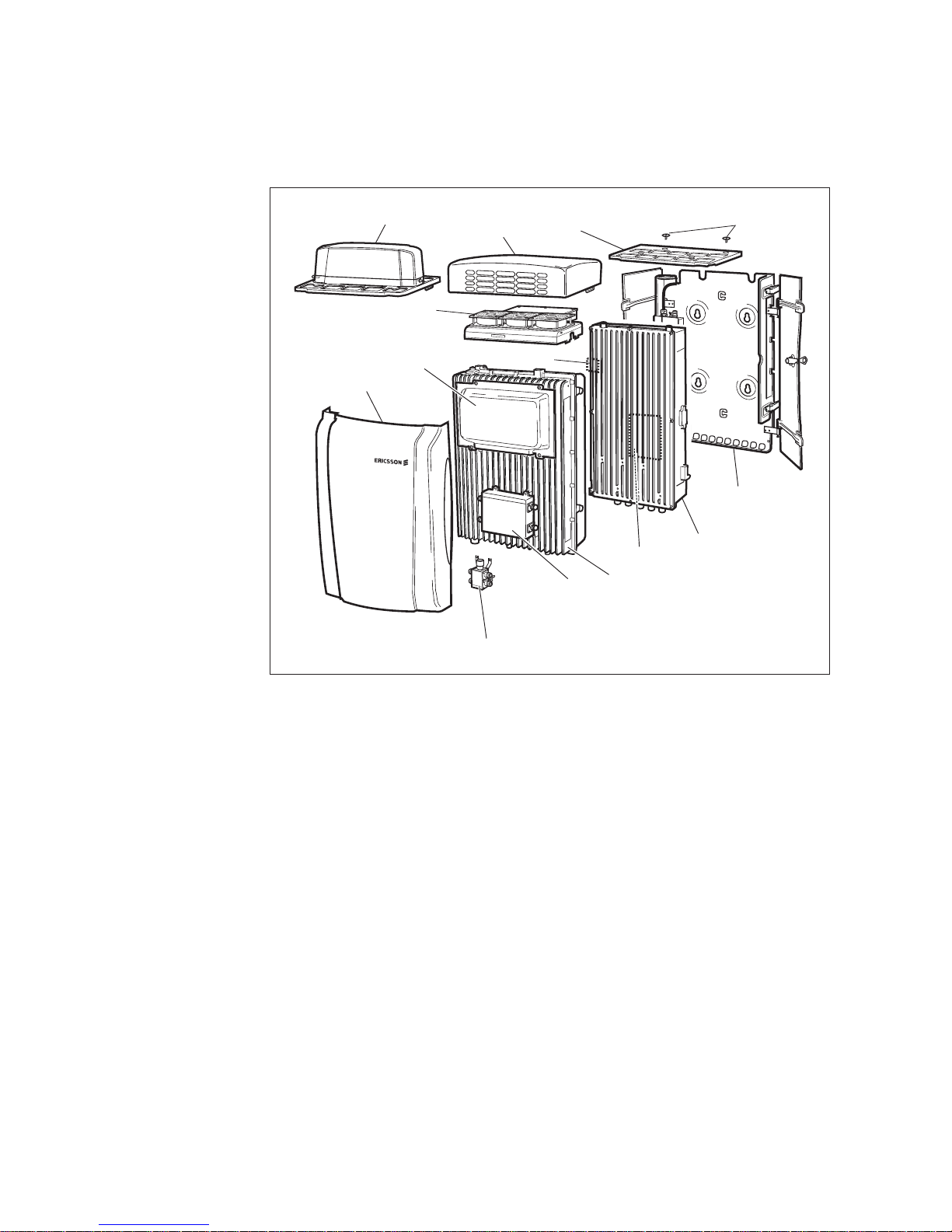
P015678B
MCB
Sunshield
TIM/PSTU
Flash Card
Sunshield
Screws
IXU (Master RBS)
MBU
Fan
RXBP
Fan Cover
RRU
Integral Sector Antenna
Integral Omni Antenna
Figure 1 RBS Ove
rview
IXU
Interface and Switching Unit
MBU Mounting Base Unit
MCB
Multicasting Box
PSTU Packet-Switched Termination Unit (available only for
RBS 2308)
RRU Remote Radio Unit
RXBP RX Bandpass Filter
TIM
Transmission Interface Module
External
optional battery backup is possible, as well as the option of having
integrat
ed antennas within the base station.
1.2 Target Groups
This section describes the target group for this manual, which is all personnel
involved in activities relating to the installation and integration of an RBS site.
3
EN
/LZT 720 0027 Uen R8A 2006-06-27
Page 12
RBS 2308 and RBS 2309 User’s Guide
TEMS
O
N
/O
FF
Y
E
S
N
O
1
2
3
4
5
6
7
8
9
*
0
#
CL
R
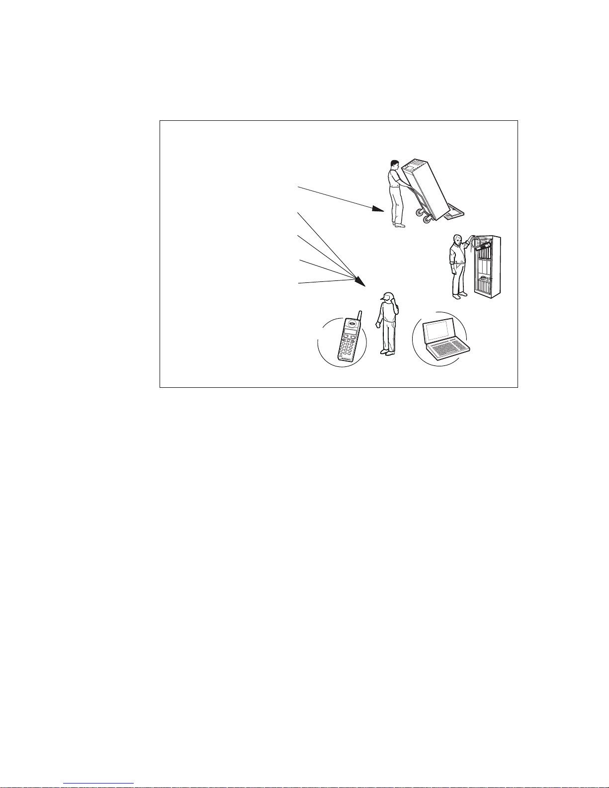
Cabinet Installation
Antenna System Tests
Site Installation Tests
RBS Site Integration
Fault Handling
OMT
Installation
Test and Integration
P008221B
Chapters Introduction, Safety Instructions and Tools and Instruments
used by all groups
Figure 2 Chapters Related to Specific Target Groups
During the whole Radio Site Implementation (RSI) process and the product’s life
cycle, the target groups require documents in addition to the above mentioned
manuals to complete the work.
Qualifications for Installation Personnel
Ericsson recommends that installation personnel possess the following skills:
• Technical college or equivalent education with an emphasis on electrical
engineering
• Familiarity with the equipment used during the installation process
• Knowledge of antenna systems
• Appropriate training and medical certificate for working at heights
• Good understanding of technical English
Qualifications for Test and Integration Personnel
Ericsson recommends that testing and integration personnel possess the
following skills:
4
EN/LZT 720 0027 Uen R8A 2006-06-27
Page 13

RBS 2308 and RBS 2309 User’s Guide
• Basic Ericsson RBS 2000 Operation and Maintenance knowledge.
Personnel should be familiar with the tools and instruments recommended
in the chapters Antenna System Tests, Site Installation Tests, and RBS
Site Integration.
• Basic GSM knowledge
• Basic RBS 2000 knowledge
• Good understanding of technical English
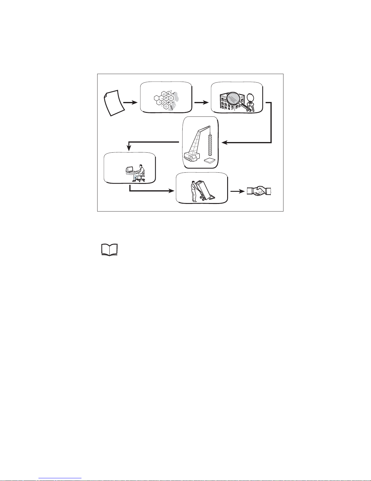
1.3 Installation and Integration Process Overview
This section describes the overall Installation and Integration process. This
process covers the work that follows the Installation Engineering process:
testing the antenna system, installing the cabinet, performing site installation
tests, and integrating the site into the network. A process overview is shown
below.
P016157A
Antenna System Tests
Site Installation Tests
RBS Site Integration
Cabinet Installation
Installation Engineering
Figure 3 Installation and Integration Process
1.4 Radio Site Implementation P rocess
This section describes the overall Radio Site Implementation process, of which
the Installation and Integration process is a part. The Radio Site Implementation
process covers the work from the initial stages of receiving an order, planning
and designing the entire network, to installing the RBS sites and integrating
them into the network.
5
EN
/LZT 720 0027 Uen R8A 2006-06-27
Page 14
RBS 2308 and RBS 2309 User’s Guide
Site Acquisition
Network Design
Acceptance (of site)
Contract is signed
P007657B
Radio Site
Installation Engineering
Civil Works
Installation & Integration
Figure 4 The Radio Site Implementation Process
For further information about the planning process, see:
Site Engineering Instruction
LZN 901 0602
Network Planning Process
The Network Planning process consists of the following activities:
• Dimensioning of network
• Dimensioning of equipment for radio, transmission, switching, operation
and maintenance
• Defining and ordering market adaptation products, for example programs
for national signalling towards the public telephone network
• Measurement of radio frequency and interference
• Producing digital maps and data
Site Acquisition
The Site Acquisition process is performed in close cooperation with the Civil
Works process and, to some extent, with the Engineering process.
The Site Acquisition process consists of the following activities:
6
EN/LZT 720 0027 Uen R8A 2006-06-27
Page 15

RBS 2308 and RBS 2309 User’s Guide
• Searching for sites and obtaining a site appraisal
• Outlining the site design and evaluating the cost
• Negotiating and signing leasing contracts
• Handling permits and arranging a handover to the Engineering personnel
Civil Works
The Civil Works process is performed in close cooperation with the Site
Acquisition process and the Engineering process.
The Civil Works process consists of the following activities:
• Preparing a d etailed civil works design of the site
• Updating the costs for the site construction
• Arranging the site construction
• Performing a site inspection and handing over an as-built document to
the Engineering personnel
Engineering
The Engineering process begins when the Site Acquisition and Civil Works
processes are complete.
The Engineering process consists of the following activities:
• Measuring and collecting information about sites
• Designing the antenna and radio configuration, and producing cable
drawings
• Making drawings showing the positions of the antenna and RBS equipment
• Defining areas of responsibility between the purchaser and the contractor
• Producing site-specific information in the Site Installation Documentation.
For more information about the results from the site engineering process, see:
Site Engineering Instruction
LZN 901 0602
Installation and Integration
The work involved in this process is performed by installation personnel, and
test and integration personnel.
7
EN
/LZT 720 0027 Uen R8A 2006-06-27
Page 16

RBS 2308 and RBS 2309 User’s Guide
Installation pers
onnel are responsible for the following activities:
• Installing the antenna system
• Installing the RBS
• Earthing the RBS
• Connecting a power supply to the RBS
• Connecting the antenna system to the RBS
• Installing cable ladders and cable ducts
• Installing battery backup
• Installing transmission cables
The test and integration personnel are responsible for the following activities:
• Performing the tests specified i n the contract and integrating the site
• Commissioning of the PSTU
• Troubleshooting if tests indicate a fault
• Recording the test results in the Site Installation Documentation, which is
returned to the engineering personnel
1.5 RBS Library Overview
For information on the RBS library and other manuals related to the RBS, see:
RBS 2000 Library Overview
LZN 302 73
1.6 Release History
In addition to editorial changes, such as correction of typographical and layout
errors, this manual has been revised as follows:
1.6.1 R7B to R8A
General
• Information about the PSTU and IP-based transmission has been added
8
EN/LZT 720 0027 Uen R8A 2006-06-27
Page 17

RBS 2308 and RBS 2309 User’s Guide
• Information about less-temperature-sensitive units with no heater has
been added
Chapter Site Installation Tests
• Section Setting IDB Parameters has been updated with new work process
Chapter PSTU Startup
• This is a new chapter
Chapter Maintenance
• A new section, Returning Hardware, has been added
Chapter Reconfiguring the RBS for IP Transmission
• This is a new chapter
1.6.2 R7A to R7B
Chapter Glossary
• New abbreviations added
1.6.3 R6A to R7A
Chapter Site Installation Tests
• Section Setting IDB Parameters updated with parameter descriptions
Chapter Maintenance
• Section Fault Localization Using OMT updated
1.6.4 R5A to R6A
The appendices EBB-01 Maintenance and Installation Instructions and EBB-06
Maintenance and Installation Instructions have been removed from the manual.
Chapter Installation of RBS
• Note about IDB added in section Replacing the Flash Card (If Applicable)
9
EN
/LZT 720 0027 Uen R8A 2006-06-27
Page 18

RBS 2308 and RBS 2309 User’s Guide
Chapter Site Insta
llation Tests
• Note about IDB adde
d in section Installing IDB
• Notes added to info
rm site personnel about indicators double-flashing
during function c
hanges
Chapter RBS Site I
ntegration
• Notes added to inf
orm site personnel about indicators double-flashing
during function
changes
Chapter Mainten
ance
• Notes added to in
form site personnel about indicators double-flashing
during function
changes
• New section, Dou
ble-Flash Indication of Function Changes, added
• Note about IDB ad
ded in section Flash Card Replacement
10
EN/LZT 720 0027 Uen R8A 2006-06-27
Page 19

RBS 2308 and RBS 2309 User’s Guide
2 Personal Health and Safety Information
2.1 Introduction
This document presents the personal health and safety information that applies
when working with Ericsson system products. The instructions included are
mandatory to ensure personal safety while working with Ericsson system
products.
Note: Reduce the risk of accidents by studying all the information carefully
before starting work. If questions arise regarding health and safety
information, contact the supervisor or the local Ericsson company for
clarification.
For information on product safety for Ericsson system products, see:
System Safety Information,
Ericsson System Products
124 46–2886
Local Regulations
Local regulations, first and foremost national regulations, override the
information in this document. Where applicable local regulations are not
available, the information herein prevails.
Product Exclusion Indication
The information in this document covers personal health and safety aspects
of all Ericsson system products. As all the information does not apply to a
specific product, the readers must familiarize themselves with the potential
hazards indicated on the product they are working with to understand which
document parts apply to their product.
2.1.1 Target Group
The target group for this health and safety information is personnel who work
with Ericsson products. All personnel who work with engineering, installation,
test, and operation and maintenance of Ericsson products must familiarize
themselves with this information.
2.1.2 Educational Requirements
The safety instructions in the relevant manuals or documents require that
persons performing work on Ericsson products have the necessary education,
1
1
EN
/LZT 720 0027 Uen R8A 2006-06-27
Page 20

RBS 2308 and RBS 2309 User’s Guide
training and compe
tence required to perform work correctly. For certain work,
additional or spec
ial training may be required, for example authorization for
Authorized Servic
e Providers (ASP). ASP is an Ericsson certification procedure.
A good understanding of technical English is required, or of the language that
the information is presented in, to ensure that these and other instructions
can be understood and complied with.
2.2 Hazard Symbols and Admonitions
This section presents the types of admonitions and hazard symbols used in
all
Ericsson documentation. There are three levels of personal health and s
afety
admonitions that indicate risk to persons: danger, warning and caution
. Hazard
symbols are used to indicate these and to present various other hazards.
The admonition levels for personal health and safety are presented in order
of severity, with danger being the highest level, warning the intermediary
and caution the lowest. When admonitions are encountered anywhere in a
document, the information included should be read and any instructions should
be followed.
2.2.1 Personal Health and Safety Admonitions
Personal health and safety admonitions are used to indicate hazardous
activities and are normally preceded by the common hazard symbol shown in
the figure below, or in specific cases by specialized symbols, see Section 2.2.2
Special Hazard Symbols on page 13.
P002643A
Figure 5 Safety Hazard Symbol
The hazard symbol is common for all three admonition levels. The three
admonition levels are defined below:
Danger! Indicates that there is an imminent hazard that is likely
to result in death or serious injury.
Note: Danger can be accompanied by other symbols
depending on the country of operation.
Warning! Indicates that there is a potential hazard that could
result in death or injury.
Caution!
Indicates a hazard that could result in minor or moderate
injury.
12
EN/LZT 720 0027 Uen R8A 2006-06-27
Page 21

RBS 2308 and RBS 2309 User’s Guide
2.2.2 Special Hazard Symbols
This section presents special hazard symbols used to indicate the risk of
chemical, electric shock, fire, heat, laser and Radio Frequency (RF) exposure
hazards:
P010387A
Figure 6 Chemical Hazard Symbol
P002645A
Figure 7 Electrical Hazard Symbol
P010385A
Figure 8 Fire Hazard Symbol
P010274A
Figure 9 Heat Hazard Symbol
P010341A
Figure 10 Laser Hazard Symbol
P002644A
Figure 11 RF E xposure Hazard Symbol
2.3 General Safety Precautions
This section presents general safety precautions to ensure that persons are not
injured when working with equipment.
• Items of jewelry, for example rings, watches and necklaces should be
removed as they can catch on moving parts, or when lifting equipment.
• Pay attention to the hazard labels and other information labels on products.
1
3
EN
/LZT 720 0027 Uen R8A 2006-06-27
Page 22

RBS 2308 and RBS 2309 User’s Guide
• Never remove or cov
er hazard symbols as this can endanger persons
working with the pr
oduct.
• Only use the tools described, in the manner indicated, in instructions.
2.4 Electric Shock Hazards
This section provides information and instructions relating to equipment
operating on voltage that entails an electric shock hazard.
Note: This information only applies to products marked with the electric shock
hazard symbol.
The term Electric Shock Hazard is defined below:
Electric Shock
Hazard
Hazard at voltage equal to or above 42.4 V peak or
60 V DC.
Danger!
Electric shock risk. Avoid both direct and indirect contact with parts connected
to mains power as this is likely to be fatal. Switch off the mains power before
starting work.
Danger!
Improper electrical installation may cause fire or electric shock that is likely to
be fatal. Only a qualified and authorized electrician is permitted to install or
modify electrical installations.
Note: Only qualified electricians are allowed to work directly with equipment
that presents an electric shock hazard.
Note: AC mains installation must be c arried out according to local regulations.
2.4.1 Safety Precautions for Working with Electrical Equipment
The following precautions must be observed when working with electrical
equipment:
• The AC mains is switched off.
14
EN/LZT 720 0027 Uen R8A 2006-06-27
Page 23

RBS 2308 and RBS 2309 User’s Guide
• Equipment exposed to moisture is protected with a tent or other equipment.
• Power cables are installed according to instructions.
• Installed cables are always clearly marked with labels.
• All personnel are familiar with and understand the warning signs on
equipment.
• Only tested electrical tools are used.
• Holes are never drilled in equipment, or walls, without ensuring that there
are no concealed cables.
2.5 Energy Hazards
This section provides information on how to avoid energy hazards.
The term energy hazard is defined below:
Energy Hazard
Hazard at a stored energy level of 20 J or an available
continuous power level of 240 VA.
2.5.1 Batteries
This section provides instructions and information on the proper handling
of batteries.
Note: Where Ericsson is not the supplier of battery equipment, see the
manufacturer’s information on battery safety.
Caution!
Improper handling of batteries can result in the batteries short-circuiting, which
can result in serious injury due to high energy levels. Exercise the necessary
care when working with batteries.
1
5
EN
/LZT 720 0027 Uen R8A 2006-06-27
Page 24

RBS 2308 and RBS 2309 User’s Guide
Lithium Batteries
Warning!
Switching poles when replacing lithium batteries can result in an explosion
that can lead to injury. Always ensure that lithium batteries are connected
to the right poles.
2.5.2 Capacitors and Uninterruptible Power Systems
This section provides information on how to avoid energy hazards in Capacitors
and Uninterruptible Power Systems (UPS).
Warning!
High energy leve
ls are present in this unit. Improper handling of the unit can
lead to short cir
cuiting that can result in serious injury. Exercise care when
working with th
is unit.
Note: Some capacitors and UPSs have energy levels above 240 VA. If this is
the case this is indicated on the product with a voltage hazard.
2.5.3 Safety Precautions for Avoiding Energy Hazards
The following precautions must be observed w hen working with batteries and
other units that present an energy hazard:
• All metallic objects worn, such as wrist watches, rings, bracelets, and so
on are removed.
• Disconnect the charger power supply until the work is complete.
• Only use insulated tools.
2.6 Fire Hazard
This section provides instructions and information on safety precautions for
preventing fire.
16
EN/LZT 720 0027 Uen R8A 2006-06-27
Page 25
RBS 2308 and RBS 2309 User’s Guide
Warning!
In the event of a fire, evacuate t
he building or equipment site and raise the fire
alarm at the closest alarm point
, or call the emergency number. Do not re-enter
a burning building under any ci
rcumstances.
Warning!
Heater in operation. Do not b
lock the heater vents or place combustible
materials close to the unit,
as this can cause a fire that can endanger life.
2.6.1 Fire Precautions
Note: When working with the installation or maintenance of equipment that
involves interfering with the fire sectioning of a building, this should be
carried out as quickly as possible.
Fire can spread to neighboring rooms. When working on equipment cable
ducts, channels and access holes might have to be opened, thereby interfering
with the fire sectioning of the building. The instructions below have to be
followed when work has been completed to restore the building’s fire sectioning:
1. Close the cable ducts and fire doors (if applicable) as soon as possible.
2. Seal cable ducts according to the regulations for the building.
3. Minimize the amount of inflammable material.
4. Remove empty packaging material from the equipment site.
5. Check that there is a functioning powder or carbon dioxide fire extinguisher
for electric apparatus at the equipment site.
2.7 Heat Hazards
This section describes how to avoid injury from hot surfaces or hot air in
equipment.
1
7
EN
/LZT 720 0027 Uen R8A 2006-06-27
Page 26
RBS 2308 and RBS 2309 User’s Guide
Caution!
Parts inside this equipment attain high temperatures during normal operation,
which can cause burns to the skin if touched without heat protective clothing.
Always use heat protective clothing when working with equipment containing hot
surfaces, or switch the equipment off and allow it to cool before starting work.
Caution!
A heater, producin
g hot air, is in use in this equipment. Direct contact with hot
air can lead to bur
ns. When the heater is in operation, avoid close contact
with the heater ai
r evacuation vent.
2.8 Mechanical Hazards
This section provides information on mechanical hazards in equipment
containing sharp edges or rotating blades.
Caution!
Sharp metal edges may exist that can cause cuts to the skin or clothing. Wear
protective gloves when handling this equipment.
Caution!
Rotating fan blad
es can cause injury to body parts that come into contact with
the blades. Blad
es in fan units continue to rotate for a period of time, even after
the fan has been s
witched off. Wait until fans have stopped rotating completely
before startin
g work on or near fans.
18 EN/LZT 720 0027 Uen R8A 2006-06-27
Page 27

RBS 2308 and RBS 2309 User’s Guide
2.9 Radio Frequency Exposure Hazards
This section provides instructio
ns and information on potential hazards related
to radio frequency (RF) electro
magnetic field (EMF) exposure from fixed radio
transmitters (as opposed to mo
bile phones).
2.9.1 General RF Safety Information
Caution!
Excessive RF exposure can result in potentially adverse health effects. If it is
suspected that RF exposure limits may be exceeded, ensure that transmitting
antennas are switched off, or reduce output power whilst working with, or
near, antennas.
Note: RF exposure limits are specified by national and international health
authorities in standards, regulations or guidelines. The limits include
wide safety margins to protect from potentially harmful tissue heating.
2.9.2 RF Safety for Installation and Maintenance Personnel
It is important that all personnel working with the installation and maintenance
of transmitting equipment and antennas have basic knowledge regarding RF
safety. They must have been informed or trained to be observant of potential
risks of RF exposure exceeding specified safety limits, and be aware of
precautionary measures necessary for differing situations.
Caution!
Do not stand or work in front of an operational antenna, unless it has been
verified or documented that RF exposure levels are within specified safety limits.
Caution!
Always be aware of other RF transmission antennas located close to the
antenna you will be working with. If the RF exposure level is unknown, contact
the equipment operator or ensure that measurements are done to verify that
levels are below specified safety limits before starting work.
1
9
EN
/LZT 720 0027 Uen R8A 2006-06-27
Page 28

RBS 2308 and RBS 2309 User’s Guide
Caution!
Broken or disconne
cted RF cables can lead to exposure levels reaching, or
exceeding, specif
ied safety limits. Repair or reconnect cables before starting
work.
Note: Working outside of the main transmission direction of ordinarily
configured antennas is in most situations possible, since the RF
exposure does not normally reach specified safety limits in these
directions.
2.10 Laser Hazards
This section provides information on working with products that have devices
that communicate through optical fibres using laser.
Note: This information only applies to products marked with the laser hazard
symbol, stating the class of laser in use.
2.10.1 Class 1 Laser
This section provides information on working with equipment containing Class
1 laser.
Products containing a Class 1 laser, according to IEC/EN 60825, are safe
to use and therefore have no requirements for cautions or warnings during
operation or maintenance procedures.
2.10.2 Class 3 Laser
This section provides information on working with equipment containing Class
3 laser.
Danger!
Never look directly into the end of a fiber optic cable, or other laser source.
Equipment that transmits laser light can cause permanent eye damage. Switch
off the laser before starting work on laser equipment.
20 EN/LZT 720 0027 Uen R8A 2006-06-27
Page 29

RBS 2308 and RBS 2309 User’s Guide
Safety Precautions for Working with Class 3 Laser
The following precautions must be observed when working with products
containing a Class 3 laser hazard symbol:
• Never look into the light emitting end of a functioning optical fibre.
• Switch off units producing the laser signal before disconnecting an optical
fibre.
2.11 Chemical Hazards
This section provides information on chemical hazards that can be present
in products.
2.11.1 Beryllium Oxide Hazard
This section provides information on Beryllium Oxide (BeO). BeO is a restricted
substance that is contained in certain components in some Ericsson products.
If a product contains BeO, this is clearly marked on the unit containing BeO.
The BeO hazard symbol is shown in the figure below.
P010382A
Figure 12 BeO Hazard Symbol
Note: This information only applies to products marked with the BeO symbol.
Danger!
This product contains Beryllium Oxide (BeO), which can cause injury to skin
or mucous membranes severe enough to endanger life or cause permanent
injury. BeO dust is created by chafing, filing, or breakage and is extremely
dangerous if inhaled, even for only a few seconds. Particles penetrating the
skin through wounds or abrasions are liable to cause chronic ulcerations. Do
not handle components containing BeO without protection.
Symptoms of BeO Poisoning
Symptoms of BeO poisoning are respiratory distress, cyanosis (grey-blue
discoloration of the skin and mucous membranes), or both. These symptoms
may develop within a week, or after a period of several years.
2
1
EN
/LZT 720 0027 Uen R8A 2006-06-27
Page 30

RBS 2308 and RBS 2309 User’s Guide
Safety Precaution
s for Working with Components Containing BeO
The following prec
autions must be observed when working with components
containing BeO:
• Do not carry loose components in pockets, bags, or containers, or tamper
with them in any way that could cause breakage or disintegration.
• Do not apply excessive heat during soldering.
• Do not break open components for inspection.
• Store components in their original packaging and do not mix them with
other components.
• Ensure that components do not become mechanically damaged.
• Use care when replacing defective components.
• Do not blow on exposed surfaces due to the danger of BeO dust.
• In case of accident, or if you feel unwell, seek medical advice immediately
and show the label where possible.
2.11.2 Battery Acid Hazard
This section provides information on chemical hazards related to lead-acid
batteries.
Caution!
Excessive heat can cause battery casing to soften and warp, potentially allowing
acid to escape. In contact with the skin, acid can cause injury, and if breathed
in, can affect the airways. Use protective equipment when replacing batteries.
Caution!
Batteries can leak electrolyte if improperly handled. Electrolyte in contact
with skin or eyes can cause injury. In the event of electrolyte injuries, rinse
the affected area with water and seek medical attention immediately. Use
protective equipment when replacing batteries.
22 EN/LZT 720 0027 Uen R8A 2006-06-27
Page 31

RBS 2308 and RBS 2309 User’s Guide
Safety Precautions for Working with Lead-acid Batteries
The following precautions must be observed when working with lead-acid
batteries:
• Eye wash facilities, and protective gloves or aprons are available.
2.11.3 Gas Explosion Hazard
Open-cell lead acid batteries can give off gases that in the event of a fire
can cause an explosion that is likely to be fatal. All battery areas must be
adequately ventilated and protected from fire.
Danger!
Do not use open-cell lead acid batteries. Open-cell lead acid batteries give off
hazardous gases that, if ignited, can cause an explosion that is likely to be fatal.
2.12 Other Hazards
This section includes safety instructions and rules for the following hazards:
• Handling Heavy Goods
• Working at Height
2.12.1 Handling Heavy Goods
This section provides instructions and rules for handling heavy goods.
Note: Follow local regulations for safety clothing and safety equipment for
hoisting and moving goods.
Falling Objects
Warning!
Risk for falling objects, work at height in progress. Falling objects can cause
serious injury or even be fatal. Always wear a helmet and avoid standing in
the danger area.
2
3
EN
/LZT 720 0027 Uen R8A 2006-06-27
Page 32

RBS 2308 and RBS 2309 User’s Guide
Overloading
Warning!
Overloading, or other wrong use of lifting devices, can cause serious injury to
anyone hit by falling equipment. Do not create an angle exceeding 90° between
lifting straps as this increases the strain on them and can cause them to snap.
Caution!
The equipment is heavy. Lifting the equipment without the aid of a lifting device
can cause injury.
Unsecured Equipm
ent
Caution!
Tip risk! Unsecur
ed equipment can tip over if not secured properly, causing
injury to person
nel. Secure products with a high center of gravity as soon as
possible to avoi
d accidents.
2.12.2 Working at Height
This section provides information about working at height.
For information on climbing instructions for working at height, see:
Safe Climbing LZY 213 715/02
Safety Precautions for Working at Height
The following precautions must be observed when working at height:
• Personnel have the appropriate training and medical certificate.
24
EN/LZT 720 0027 Uen R8A 2006-06-27
Page 33

RBS 2308 and RBS 2309 User’s Guide
• A full-body safety harness and safety helmet are available.
• Adequate protective clothing, essential in cold and wet weather, is available.
• All lifting devices are tested and approved, and ready for use.
• All personnel in the area are wearing helmets.
2
5
EN
/LZT 720 0027 Uen R8A 2006-06-27
Page 34

RBS 2308 and RBS 2309 User’s Guide
26
EN/LZT 720 0027 Uen R8A 2006-06-27
Page 35

RBS 2308 and RBS 2309 User’s Guide
3 System Safety Information
3.1 Introduction
This document presents the system used for presenting system safety
information for Ericsson products. The instructions included are mandatory to
ensure product safety while working with Ericsson products.
Local regulations must be taken into consideration. The system safety
information in this document is in addition to local regulations.
Note: Reduce the risk of accidents by studying all the instructions carefully
before starting work. If questions arise regarding the safety instructions,
contact the supervisor or the local Ericsson company for clarification.
For information o n personal health and safety for Ericsson system products,
see:
Personal Health and Safety
Information, Ericsson System
Products
124 46–2885
Local Regulations
Local regulations, first and foremost national regulations, override the
information in this document. Where applicable local regulations are not
available, the information herein prevails.
Product Exclusion Indication
The information in this document covers system safety information for all
Ericsson system products. As all the information does not apply to a specific
product, the readers must familiarize themselves with the potential hazards
indicated on the product they are working with to understand which document
parts apply to their product.
3.1.1 Target Group
The target group for this system safety information is personnel who work
with Ericsson products. All personnel who work with engineering, installation,
test, and operation and maintenance of Ericsson products must familiarize
themselves with this information.
2
7
EN
/LZT 720 0027 Uen R8A 2006-06-27
Page 36

RBS 2308 and RBS 2309 User’s Guide
3.1.2 Educational Requi
rements
The product safety
instructions in the relevant manuals or documents require
that persons perfo
rming work on Ericsson products have the necessary
education, train
ing and competence required to perform work correctly. For
certain work, add
itional or special training may be required, for example
authorization fo
r Authorized Service Providers (ASP). ASP is an Ericsson
certification p
rocedure.
A good understanding of technical English is required, or of the language
that the information is presented in, to ensure that these instructions can be
understood and complied with.
3.2 Admonitions and Safety Symbols
This section presents the types of admonitions and safety symbols used in all
documents for Ericsson system products. There are two types of system safety
admonitions that indicate risk to products: Do! and Stop!. When admonitions
are encountered anywhere in a document, the information included should be
read and any instructions should be followed.
The figures below show the symbols used to i ndicate product safety
admonitions:
Figure 13 Do Safety Symbol
Figure 14 Stop Safety Symbol
The terms Do! and Stop! are defined below:
Do!
Indicates an action that must be performed to prevent
equipment damage, software corruption, data loss or
service interruption.
Stop!
Indicates that action must be avoided to protect
equipment, software, data or service.
The term “Note” is used to present important information that might otherwise
be overlooked.
3.2.1 Special Hazard Symbols
This section presents special hazard symbols used to indicate the risk of
Electrostatic Discharge (ESD):
28
EN/LZT 720 0027 Uen R8A 2006-06-27
Page 37

RBS 2308 and RBS 2309 User’s Guide
P002646A
Figure 15 Electrostatic Discharge Hazard Symbol
3.3 Batteries
This section provides information on damage that can be caused to products
containing batteries that are damaged.
3.3.1 Overheated Batteries
Caution!
Do! Check batteries for signs of overheating. The casing surrounding
overheated batteries can be soft and warped. Replace damaged batteries
according to instructions.
If it is suspected that batteries are overheated, check the following:
• The internal temperature of the equipment is below +60°C (140°F).
• Batteries have not leaked.
Corrective Actions
1. Replace overheated batteries.
2. Treat leakages from batteries as described in Section 3.3.2 Treating
Hazardous Waste from Leaks on page 29.
3.3.2 Treating Hazardous Waste from Leaks
Caution!
Do! Check batteries for acid leakage. Acid can corrode the product. Replace
leaking batteries according to instructions.
2
9
EN
/LZT 720 0027 Uen R8A 2006-06-27
Page 38

RBS 2308 and RBS 2309 User’s Guide
In case of spillage
of hazardous substances, there should always be sufficient
absorbers or neutr
alizing materials available on site. There is a danger of
spillage occurrin
g when installing, removing, replacing or servicing batteries.
The absorbers and
neutralizing materials must be suitable for the hazardous
substances invol
ved. Typical neutralizing agents are shown inTable 1 on
page 30.
Table 1 Typical Neutralizers
Typical Neutralizers
Chemical Compound
Baking soda (bicarbonate) NaHCO
3
Sal soda Na2CO3IOH2O
Soda ash Na2CO
3
Note: Absorbers and neutralizing products will vary, depending on the c ountry
and battery manufacturer. Consult the battery manufacturer for specific
details of absorbers and neutralizing materials.
3.4 Electrical Installation
This section provides information on ensuring that AC and DC powered
products are not damaged due to improper installation.
Caution!
Stop! Do not install or modify AC or DC powered equipment unless you are a
qualified and authorized electrician. Improper installation work can seriously
damage the equipment.
3.4.1 Safety Precautions for Working with Elec trical Installations
The following precautions must be observed when working with electrical
installations:
1. Ensure that approved circuit breakers or fuses are installed.
2. Ensure that the cables used have a sufficient cross-sectional area in
accordance with product requirements and local laws and regulations.
3. Ensure that conductors are connected according to the connection diagram.
4. Label the cables correctly.
5. Check the installation work upon completion.
30
EN/LZT 720 0027 Uen R8A 2006-06-27
Page 39

RBS 2308 and RBS 2309 User’s Guide
3.5 Electrostatic Discharge
This section provides informatio
n and instructions on Electrostatic Discharge
(ESD) product safety. ESD is def
ined below.
ESD
A static electric charge accum
ulates when a body rubs
against clothes, slides again
st a chair, when shoes rub
against a floor, or when ordin
ary plastics are handled,
and so on. The electrostatic c
harge can remain for a
considerable length of tim
e and is discharged when the
body comes into contact wit
h conductive material.
An ESD wrist strap must be us
ed when working with ESD sensitive components,
even in equipment rooms fi
tted with ESD protective floor covering. Although
ESD floor covering reduce
s the risk of ESD, if the wrong type of shoes are
used, or if the person is a
lready charged when they enter the room, the floor
covering in itself does
not protect from this, and therefore an ESD wrist s trap
must be used.
01_0250A
Figure 16 ESD wrist strap
The ESD wrist strap contains a resistor with resistance greater than 1 M in the
cable to protect the operator. The resistance value is low enough to discharge
the electrostatic voltage. The ESD wrist strap must be connected to ground.
Instructions for ESD Wrist Strap Use
1. Place the ESD wrist strap around your wrist and insert the connector at the
other end to the ground (earth) terminal on the equipment.
2. Always use the wrist strap when and where its use is required.
Note: Test the ESD wrist strap regularly.
3
1
EN
/LZT 720 0027 Uen R8A 2006-06-27
Page 40

RBS 2308 and RBS 2309 User’s Guide
3.5.1 Handling Printed B
oard Assemblies and IC Components
Note: Treating all
components as if they are ESD sensitive, whether they
have IC components
or not, reduces the risk for ESD and significantly
reduces the opera
ting time between failure.
Caution!
Stop! This product contains components sensitive to ESD. Use an approved
ESD wrist strap, connected to the product grounding point, to avoid damaging
these components.
Caution!
Do! Always use an approved ESD wrist strap when working with sensitive
equipment. Damage to components mounted on printed board assemblies can
occur if an ESD wrist strap is not used.
3.5.2 Storing and Trans
porting Printed Board Assemblies and IC
Components
When storing or t
ransporting printed board assemblies or IC components,
ensure one of the
following:
• The item is store
d or transported in its original packaging, or in other
anti-ESD mater
ial.
• The item is stor
ed or transported in a conductive material, or a special IC
carrier that ei
ther short-circuits or insulates all leads of the components.
3.6 Equipment Handling
This section provides information on how to avoid damage to products when
handling them.
32
EN/LZT 720 0027 Uen R8A 2006-06-27
Page 41

RBS 2308 and RBS 2309 User’s Guide
Caution!
Do!
Tip risk! This equipment has a high center of gravity without all units installed.
Secure the equipment before opening the door.
Caution!
Stop! Never lift a unit by the cables as this can damage the equipment.
3.7 Ground Connection
This section provides information on product grounding (earthing) safety.
Note: The terms “grounding” and “earthing” are synonyms.
Caution!
Do! Products not connected to ground risk being damaged by overvoltage or
overcurrent. Always connect products to ground according to instructions.
3.8 Lightning Protection
This section provides infor
mation on protecting products from damage due to
lightning where a lightning
protection system is available.
Caution!
Do! Connect products to the
lightning protection system to protect the
equipment from transient s
urges.
3
3
EN
/LZT 720 0027 Uen R8A 2006-06-27
Page 42

RBS 2308 and RBS 2309 User’s Guide
34
EN/LZT 720 0027 Uen R8A 2006-06-27
Page 43

RBS 2308 and RBS 2309 User’s Guide
4 Tools and Instruments
This section contains lists of all tools and instruments recommended for the
complete installation of the RBS 2308 and RBS 2309.
4.1 Tools for Installation of RBS 2308 and RBS 2309
Table 2 Basic Tools for Installation
Description
Specification
Adjustable spanner 10"
–
Drilling mach in e
–
Knife
(1)
–
Measuring tape
(1)
6m
Pen
–
Screwdrivers
(1)
Torx: T20 and T30
Screwdrivers
3 mm and 5.5 mm
Side cutting pliers
(1)
–
Snip nos e pliers
–
Socket set
(1)
10–19mm
Spirit le ve l
(1)
–
Torquewrench 5–25Nm
U wrenches
(1)
13 mm, 16 mm, 17 mm, 20 mm and 22 mm
Wire stripper
(1)
0.2–6mm
2
(1) Included in Personal Tool Set, Product Number LTT 601 135/1.
Table 3 Special Tools for Installation
Description
Specification
Product Number
Crimping tool set for grounding
LTT 601 86
Torque wrench
for N connector LSS 103 25/1
Torque wrench
for TNC connector
LTT 601 93
U-key, 32 mm
(1)
for 7/16 connecto r LSB 107 12/5
(1) Requires torque set 20–100 Nm, product number LTT 601 141/1.
4.1.1 Documentation
The following documents are required for the installation procedure:
3
5
EN
/LZT 720 0027 Uen R8A 2006-06-27
Page 44

RBS 2308 and RBS 2309 User’s Guide
• Completed and appr
oved record prepared during site preparation
• Site Installation Documentation (prepared by the Installation Engineering
department)
Standard Site Material Installation
Instructions
EN/LZT 720 0014
4.2 Equipment for Antenna System Tests
Table 4 Test Equipment for Antenna System Tests
Description
Specification
Product Number
Antenna tester set
Anritsu Site Master S331D LPK 102 101/10
Antenna tester
accessories
Accessories to the Anritsu Site
Master for micro RBSs
(1)
LPK 102 107/1
(1) Requires antenna tester set, product number L P K 102 101/10.
The Anritsu Site Master S331D is recommended for the Antenna System Tests,
but the following Site Master models can still be used if available: S251A/B and
S331A/B/C for GSM 800/900/1800/1900 antenna systems.
4.2.1 Documentation
The following documents are required for the antenna system tests:
• Site Installation Documentation
• A test record
For more detailed information on the Anritsu Site Master, see:
Anritsu Site Master User’s Guide (included in Antenna Tester
Set)
Note: Instructions for Site Master models S251A/B and S331A/B/C for GSM
800/900/1800/1900 antenna systems are not included in this document.
When using any of these models ensure that all necessary accessories
are included. See:
Standard Tools and Equipment
Catalogue
LZT 720 0013
36
EN/LZT 720 0027 Uen R8A 2006-06-27
Page 45

RBS 2308 and RBS 2309 User’s Guide
4.3 Equipment for Site Installation Tests
Table 5 Test Equipment for Site Installation Tests
Description
Specification
Product Number
Fluke79III Multimeter
LPK 102 024/3
Torx T20
(1)
Torx screwdriver
–
(1) Included in Personal Tool Set, product number LTT 601 135/1.
There are different versions of the OMT depending on the BTS software
installed in the RBS. See table below.
Table 6 OMT Kits
Product
Name
Description Product No.
BSS SW
Compatibility
NTM 201 2289/3 Up to BSS R9.1
NTM 201 2289/4 Up to BSS R10
NTM 201 2289/5 Up to BSS R11
OMT Kit • Cable
• CD comprising OMT
SW and manual
NTM 201 2289/6 Up to BSS R12 and
BSS 06A
(1)
(1) BSS 06A is the successor to BSS R12
4.3.1 Documentation
The following documents are required for the site installation tests:
• A completed test record from antenna system tests
• A test record for site installation tests
OMT User’s Manual (included in
OMT Kit )
EN/LZN 720 0001
4.4 Equipment for PSTU Startup
Table 7 Basic Tools for PSTU Startup
Description
Specification
PC equipped with a VT100 terminal
emulator program and a standard
RS-232 serial port
–
Standard RS-232 serial cable. (The
standard OMT cable included in the
OMT kit can also be used.)
–
3
7
EN
/LZT 720 0027 Uen R8A 2006-06-27
Page 46

RBS 2308 and RBS 2309 User’s Guide
4.4.1 Documentation
The following docu
ments are required for the PSTU startup:
PSTU Command Description 1/190 82-LZA 701 0001
PSTU Alarm OPIs
4.5 Equipment for RBS Site Integration
Table 8 Test Equipment for RBS Site Integration
Description
Specification
Product Number
Loop forward/
backward board
Transmission test board
LPY 107 757/1
TEMS Kit GSM 800/1900
FAB 801 2524
TEMS Kit GSM 900/1800/1900
FAB 801 2523
4.5.1 Documentation
The following document is required for the RBS site integration:
TEMS Investigation GSM Manual
(included in TEMS Kit)
LZT 108 2684
4.6 Equipment for Maintenance
Table 9 Basic Tools for Maintenance
Description
Specification
Adjustable spanner 10"
–
Knife
(1)
–
Screwdrivers
(1)
Torx: T20 and T30
Screwdrivers
3 mm and 5.5 mm
Side cutting pliers
(1)
–
Snip nose pliers
–
Socket set
(1)
–
Torque wr ench
(1)
5–25Nm
38 EN/LZT 720 0027 Uen R8A 2006-06-27
Page 47

RBS 2308 and RBS 2309 User’s Guide
Description
Specification
U wrenches
(1)
13 mm, 16 mm and 17 mm, 20 mm and 22 mm
Wire stripper
(1)
0.2–6mm
2
(1) Included in Persona l Tool Kit, product numbe r LTT 601 135/1.
Table 10 Special Tools for Maintenance
Description
Specification
Product Number
Fluke 79 III Multimeter
LPK 102 024/3
Torque wrench
for N connectors LSS 103 25/1
Torque wrench
for TNC connectors
LTT 601 93
There are different versions of the OMT depending on the BTS software
installed in the RBS. See table below.
Table 11 OMT Kits
Product
Name
Description Product No.
BSS SW
Compatibility
NTM 201 2289/3 Up to BSS R9.1
NTM 201 2289/4 Up to BSS R10
NTM 201 2289/5 Up to BSS R11
OMT Kit • Cable
• CD comprising OMT
SW and manual
NTM 201 2289/6 Up to BSS R12 and
BSS 06A
(1)
(1) BSS 06A is the successor to BSS R12
Table 12 Basic Tools for PSTU Maintenance in the RBS 2308
Description
Specification
PC equipped with a V
T100 terminal
emulator program
and a standard
RS-232 serial po
rt
–
Standard RS-232 serial cable. (The
standard OMT cable included in the
OMT kit can also be used.)
–
4.6.1 Documentation
The following documents are required for the maintenance work:
OMT User’s Manual (included in
OMT Kit)
EN/LZN 720 0001
3
9
EN
/LZT 720 0027 Uen R8A 2006-06-27
Page 48

RBS 2308 and RBS 2309 User’s Guide
RBS 2308, RBS 2309, and RBS 2109
Hardware Reference Manual
EN/LZT 720 0058
The following documents are required for maintenance of the PSTU in the
RBS 2308:
PSTU Command Description 1/190 82-LZA 701 0001
PSTU Alarm OPIs
4.7 Kit Specifica
tions
For a specific
ation of all required kits, see:
Standard Tools and Equipment
Catalogue
EN/LZT 720 0013
40
EN/LZT 720 0027 Uen R8A 2006-06-27
Page 49

RBS 2308 and RBS 2309 User’s Guide
5 Installation of RBS
5.1 Introduction
This document describes how to install the RBS 2308 and RBS 2309.
Target Group
The target group for this instruction is personnel involved in the installation of
an RBS.
5.2 Preconditions
This section provides preconditions that must be met before starting the
installation work.
Note: Specific preconditions exist for wall and pole mounting.
Documentation
This section presents additional documents required for the installation
procedure.
Ensure that the following documents are available:
• Completed and approved record prepared during site preparation
• Site Installation Documentation (prepared by the Installation Engineering
department)
Standard Site Material Installation
Instructions
EN/LZT 720 0014
General Preconditions
Before starting site work, ensure the following:
• Site access permission received
• Ordered RBS, equipment, specified tools and other necessary facilities
have been delivered
• Site power is available
• Site Grounding Point is available
4
1
EN
/LZT 720 0027 Uen R8A 2006-06-27
Page 50

RBS 2308 and RBS 2309 User’s Guide
Note: The terms ear
thing and grounding are synonymous.
• Transmission line from the BSC is available
• During outdoor installation, protection for the RBS is available in case of
bad weather
Note: After installation, if the surrounding temperature changes between hot
and cold, then to avoid humidity damage the RBS must not be left
without power for more than 48 hours.
To switch on the RBS, see Chapter Site Installation Tests:
If any of the above preconditions cannot be complied with, then contact the site
supervisor or person responsible for the activity that has been missed.
Additional Preconditions for Wall-Mounted RBS
Before installing the RBS on a wall, ensure that the following preconditions
are met:
• The type of fasteners are suitable for the kind of wall material on which
the RBS is to be mounted
• The contact surfaces on the Mounting Base Unit (MBU) are supported by
the wall. If not, then a wall bracket is required
If any of the above preconditions cannot be complied with, then contact the site
supervisor or person responsible for activity that has been missed.
Additional Preconditions fo r Pole-Mounted RBS
Before installing the RBS on a pole, ensure that the following preconditions
are met:
• The pole must have the required diameter 60 – 114 mm
• A wall bracket is available
• A mast fixture set is available
If any of the above preconditions cannot be complied with, then contact the site
supervisor or person responsible for activity that has been missed.
5.3 Torque Settings
This section presents the recommended torque values to be used when
installing the RBS.
The tools needed for the installation are found in Chapter Tools and Instruments.
42
EN/LZT 720 0027 Uen R8A 2006-06-27
Page 51

RBS 2308 and RBS 2309 User’s Guide
Table 13 Recommended Torque, Screws and Nuts
TorqueDimension
Ncm Nm
lbf-in lbf-ft
Notes
M3 110 ± 7
–
9.7 ± 0.6
––
M3 80 ± 7
–
7.1 ± 0.6
–
Reduced
torque for
plastic covers
M4 260 ± 15
–
23.1 ± 1.3
––
M4 170 ± 15
–
15.1 ± 1.3
–
Reduced
torque for
captive screws
M6
–
8.8 ± 0.5
–
6.5 ± 0.4
–
M8
–
21 ± 1.3
–
15.5 ± 1.0
–
M10
–
41 ± 2.5
–
30.2 ± 1.8
–
Table 14 Recommended Torque, Connectors
Torque
Connector
Ncm Nm
lbf-in lbf-ft
Notes
TNC
–
1.7 ± 0.15
–
1.3 ± 0.11
–
N
–
2.7 ± 0.20
–
2.0 ± 0.15
–
5.4 Installation Procedure
This section describes the installation procedure for the RBS.
4
3
EN
/LZT 720 0027 Uen R8A 2006-06-27
Page 52

RBS 2308 and RBS 2309 User’s Guide
Fig
ure 17 The RBS Installation Process
44
EN/LZT 720 0027 Uen R8A 2006-06-27
Page 53

RBS 2308 and RBS 2309 User’s Guide
5.4.1 Unpacking RBS
Unpack the RBS on-site. To avoid damage, the RBS should not be unpacked
elsewhere and then transported to site.
Caution!
Stop! This product contains co
mponents sensitive to ESD. Use an approved
ESD wrist strap, connected to t
he product grounding point, to avoid damaging
these components.
In order to avoid damage to components due to electrostatic discharges during
unpacking, personnel must not come in contact with the connectors of the RBS.
Ensure that the correct material has been delivered. If the material is damaged,
complain immediately to the supervisor or the transport company.
5.4.2 Installing the Wall Bracket
Note: This section is only applicable for walls with very rough surfaces or
when the RBS is to be mounted on a pole.
This section describes how to install the wall bracket.
The wall bracket is for use as a complement to the mounting interface of the
Mounting Base Unit (MBU). Typical applications are rough surfaces and other
conditions where the mounting interface for the MBU is not flat. The plate must
also be used if the RBS is to be installed on a pole. See applicable section
below.
4
5
EN
/LZT 720 0027 Uen R8A 2006-06-27
Page 54

RBS 2308 and RBS 2309 User’s Guide
5.4.2.1 Installing the Wal
l Bracket on a Wall (Alternative)
1.
Place the drilling template in the position where the RBS is to be
located.
2. Use a spirit level to check that the drilling template is horizontal.
3.
Mark the position of the holes to
be drilled.
Note: The wall bracket must not
be used as a drilling template,
to avoid damaging the rust
protection surface.
P010150B
D
R
IL
L
T
E
M
P
L
A
T
E
F
O
R
W
A
L
L
B
R
A
C
K
E
T
R
e
c
o
m
e
n
d
e
d
h
o
le
s
UP
A
lte
rn
a
te
h
o
le
s
4.
Remove the template and drill the holes for the fasteners.
5.
Install the wall bracket and
secure it in position with all the
screws provided.
UP
P010151A
6.
Loosen the four nuts, on which the MBU is to be hung, until only a few
threads remain exposed.
5.4.2.2 Installing the Wall Bracket on a Pole (Alternative)
1. Choose the appropriate holes. See Figure below.
46
EN/LZT 720 0027 Uen R8A 2006-06-27
Page 55

RBS 2308 and RBS 2309 User’s Guide
P010152A
B
A
A
B
UP
AB
Figure 18 Installatio
n Alternatives
A
Holes used for vertical poles
B
Holes used for horizontal poles
2. Ensure that the wa
shers are mounted correctly and attach the two clamps
with the screws an
d washers. See Figure below.
Note: Ensure that
the recess is attached in the correct direction.
P010171A
Recess
UP
Figure 19 Fastening Clamps to the Wall Bracket
3. Position the wall bracket on the pole and mount the clamps, tightening
the screws alternately to avoid bending them. Ensure that the washers
are mounted correctly.
4
7
EN
/LZT 720 0027 Uen R8A 2006-06-27
Page 56

RBS 2308 and RBS 2309 User’s Guide
P010170B
Recess
Figure 20 Installing the Wall Bracket on the Pole
5.4.3 Installing the MBU
This section describes how to install the Mounting Base Unit (MBU) on a wall or
wall bracket.
5.4.3.1 Installing the MBU on a Wall
1.
Place the drilling template in the position where the RBS is to be
situated.
2. Use a spirit level to check that the drilling template is horizontal.
3.
Mark the position of the
applicable holes to be drilled.
Note: To avoid damaging the
rust protection surface, the MBU
must not be used as a drilling
template.
P010234B
D
R
IL
L
T
E
M
P
L
A
T
E
F
O
R
W
A
L
L
B
R
A
C
K
E
T
R
e
c
o
m
e
n
d
e
d
h
o
l
e
s
UP
A
lte
r
n
a
t
e
h
o
le
s
4.
Remove the template and drill holes for the fasteners most suitable
for the wall material.
5.
Insert the fasteners and tighten them, remembering to leave enough
threads protruding to hang the M BU on.
48
EN/LZT 720 0027 Uen R8A 2006-06-27
Page 57

RBS 2308 and RBS 2309 User’s Guide
6. Hang the MBU on the bolts,
applying just enough downward
pressure to ensure that the
screws fit in the keyholes.
P010120A
7.
Tighten the four bolts.
8.
Connect site earthing to the
MBU.
Note: In configurations with
more than one RRU and a 2-wire
DC Supply, an extra earthing
cable must be connected
between the RBSs.
P010190B
8 - 9 mm
4
9
EN
/LZT 720 0027 Uen R8A 2006-06-27
Page 58

RBS 2308 and RBS 2309 User’s Guide
5.4.3.2 Installing the MBU
on a Wall Bracket
1.
Install the MBU on the four
screws situated on the wall
bracket. Ensure that the
fastening screws are properly
fitted in the key holes.
P010180A
2. Use a spirit level to check that the MBU is positioned vertically.
3.
If the MBU is not in a vertical
position the then inclination can
be corrected by adjusting the
four distance nuts on the wall
bracket. To do this, the MBU
must be removed. Leave the
locking nuts on the fastening
screws.
Note: Do not loosen the inner
nuts. The inner nuts secure
the fastening screws to the wall
bracket.
Distance Nut
Inner Nut
Locking Nut
Fastening screws
P010179A
50 EN/LZT 720 0027 Uen R8A 2006-06-27
Page 59

RBS 2308 and RBS 2309 User’s Guide
4. When the wall bracket is correctly adjusted, put back the MBU and
tighten the four locking nuts.
5.
Connect site earthing to the
MBU.
Note: In configurations with
more than one RRU and a 2-wire
DC Supply, an extra earthing
cable must be connected
between the RBSs.
P010190B
8 - 9 mm
5.4.4 Connecting Power
This section describes how to connect the power cable(s) to the RBS. The
section includes instructions for both AC and DC cables.
Danger!
Electric shock risk. Avoid both direct and indirect contact with parts connected
to mains power as this is likely to be fatal. Switch off the mains power before
starting work.
Danger!
Improper electrical installation may cause fire or electric shock that is likely to
be fatal. Only a qualified and authorized electrician is permitted to install or
modify electrical installations.
Note: Protective Earth must be connected to the earth terminal when
connecting power supply.
5
1
EN
/LZT 720 0027 Uen R8A 2006-06-27
Page 60

RBS 2308 and RBS 2309 User’s Guide
The Protective Ear
th terminal is located in the MBU, indicated by the earth
symbol, see the Fig
ure below.
Figure 21 Protective Earth
Note: Protective Earth connection is essential.
1.
Remove the MBU lid f rom the
MBU.
P010371A
AC
1
DC
1
RRU
1
0
0
0
2.
Cut the cable to the appropriate l ength.
3. Remove the cable insulation and
strip the conductors.
P010308A
52 EN/LZT 720 0027 Uen R8A 2006-06-27
Page 61

RBS 2308 and RBS 2309 User’s Guide
4. Mount all cable inlet parts.
P010309A
5.
Route the AC mains cable into
the left inlet and the DC supply
cable into the right inlet. Then
tighten the cable glands.
P010310A
5.4.4.1 Connecting AC Mains
This section describes how to connect AC mains cable (if applicable).
1.
Ensure that the site power is turned off.
2.
Connect the AC cable to the
dedicated terminals.
P010119A
AC
1
DC
1
RRU
1
0
0
0
5
3
EN
/LZT 720 0027 Uen R8A 2006-06-27
Page 62

RBS 2308 and RBS 2309 User’s Guide
3. Ensure that the protective earth
is properly connected.
P010181A
LL
L = Line
PE = Protective Earth
PE
4.
If DC is not to be connected, put back the MBU cover onto the MBU.
5.4.4.2 Connecting DC Supply
This section describes how to connect the DC supply cable (if applicable).
1.
Ensure that the site power is turned off.
2.
Connect the DC cable to the
dedicated terminals. If 2-wire is
used, set the ground selector to
2-W.
P010511B
PE = Protective Earth
PE
48 V
48 V_RTN
2-W
54 EN/LZT 720 0027 Uen R8A 2006-06-27
Page 63

RBS 2308 and RBS 2309 User’s Guide
3.
If 3-wire is used, set the ground
selector to 3-W.
P010510B
3-W
48 V
48 V_RTN
PE = Protective Earth
PE
4. Ensure that the prote
ctive earth is properly connected.
5.
Put back the MBU cover.
5.4.5 Replacing the Flas
h Card (If Applicable)
This section descr
ibes how to replace the existing flash card in the IXU. This is
done only if a flash
card, preloaded with site-specific data, is provided.
Note: Using the OM
T, always reload the software and install the appropriate
IDB after moving a
used flash card to another cabinet. This ensures
consistent soft
ware and correct configuration.
For information
about preloading the flash card, see Chapter Maintenance.
5
5
EN
/LZT 720 0027 Uen R8A 2006-06-27
Page 64

RBS 2308 and RBS 2309 User’s Guide
1. Remove the cover. Remove the
existing flash card by pulling up
the adjacent black plastic lever
and then pushing it down to eject
the card.
P010366A
2.
Insert the new flash c ard, push
it in, and reset the release lever
(ensuring that the card is in
position).
P010157A
Flash
Card
3. Put back the cover.
5.4.6 Installing the IXU
This section describes how to install the Interface and Switching Unit (IXU)
on the MBU.
Note: This section is valid only for the master RBS. IXU is not used in
extension RBSs.
56
EN/LZT 720 0027 Uen R8A 2006-06-27
Page 65

RBS 2308 and RBS 2309 User’s Guide
1. Hook the IXU onto the MBU, and
secure it with the two screws
under the MBU.
P010365B
2.
Connect the IXU AC/DC cable.
P010174B
3. Loosen the eight screws on the IXU and open the cover.
5
7
EN
/LZT 720 0027 Uen R8A 2006-06-27
Page 66

RBS 2308 and RBS 2309 User’s Guide
4.
Connect the Y link cable to the
applicable connection port on
the IXU, see Table below.
P010155B
Y link Y link Y link
1-4 5-8 9-12
Y link Y link Y link
1-4 5-8 9-12
Note: Blanking plugs must be inserted in the unused cable inlets.
Table 15 Y link Connection Port
RBS Connection Port
RRU 1 Y link 1 – 4
RRU 2 Y link 5 – 8
RRU 3 Y link 9 – 12
Connectin
g the RBS 2302 to a New Master Cabinet in a Mixed Micro
Configura
tion
This secti
on describes how to connect RBS 2302 cabinet cables (TXL and
PCM) to th
e new master cabinet (RBS 2308 or RBS 2309) in a mixed micro
configur
ation. See also Section 5.5 Installing Mixed Micro Configurations on
page 85.
58
EN/LZT 720 0027 Uen R8A 2006-06-27
Page 67

RBS 2308 and RBS 2309 User’s Guide
1. Remove the TXL cover on the
new master cabinet IXU.
2.
Connect the TXL bus cable from the RBS 2302 cabinet to the new
master cabinet.
3.
Connect the PCM cable from the RBS 2302 cabinet to the new master
cabinet, according to Connecting PCM Coaxial 75 Ω or Connecting
PCM Coaxial 100/120 Ω.
Continue the RBS 2308 and RBS 2309 installation according to Section 5.4
Installation Procedure on page 43.
5
9
EN
/LZT 720 0027 Uen R8A 2006-06-27
Page 68

RBS 2308 and RBS 2309 User’s Guide
Connecting Extern
al Cables
This section descr
ibes how to connect different external equipment, for example
MINI LINK™ or trans
mission, see Figure below.
Note: To simplify
the cable connections, the connection frame on the IXU
can be removed.
EXT.ALARM 1-4
-48V
LINK
PORT A PORT C PORT B PORT D
P010211A
Figure 22 Connection Ports on the IXU
1.
Remove the connection frame
from the IXU.
P010126A
2. Remove the cable gland parts
and remove the sealing insert.
Route the cable through the
cable gland parts and strip the
cable insulation. Cut the cable
screen according to the figure.
P010463B
10 mm
60 EN/LZT 720 0027 Uen R8A 2006-06-27
Page 69

RBS 2308 and RBS 2309 User’s Guide
3.
Strip the conductors and fold
back the cable screen over the
inner part of the cable gland.
P010464B
10 mm
4. Insert the cable into the most
suitable inlet and tighten the
cable gland.
P010512A
5.
Strip the conductors and loosen
the termination blocks. Fasten
the conductors by inserting a
screwdriver in the upper slot.
Max 3.5 mm
P010229A
6
1
EN
/LZT 720 0027 Uen R8A 2006-06-27
Page 70

RBS 2308 and RBS 2309 User’s Guide
6.
If applicable, connect the
external alarm cables. See also
Figure 22 on page 60.
P010209A
EXT. Alarm. 1
EXT. ALARM.1. RTN
EXT. Alarm. 2
EXT. ALARM.2. RTN
EXT. Alarm. 3
EXT. ALARM.3. RTN
EXT. Alarm. 4
EXT. ALARM.4. RTN
EXT.ALARMS
7.
If applicable, connect the 48 V
LINK cable. SeealsoFigure22
on page 60.
P010514A
- 48 V
LINK
48 V
48 V_RTN
8.
Connect the applicable
transmission cables. The
figure shows port A, but is also
valid for port C, B, and D.
For information on how to
connect and earth PCM lines,
see:
Page 64 for 75 coaxial cable,
Page 65 for 100/120 twisted
pair.
For information on how to
connect IP-based transmission,
see:
Page 66 for optical Ethernet,
Page 66 for electrical Ethernet.
P0102010A
PORT. A. IN. P. LINE
PORT. A. IN. N. LINE
PORT. A. IN. GND
PORT. A. OUT. P. LINE
PORT. A. OUT. N. LINE
PORT. A. OUT. GND
PORT A
62 EN/LZT 720 0027 Uen R8A 2006-06-27
Page 71

RBS 2308 and RBS 2309 User’s Guide
9.
Put back the connection frame.
10.
Set the transmission impedance
for each port, using the selector
switches.
If an IXU with a separately
installed Transmission Interface
Module (TIM) is used, then the
switches are located on the
bottom of the TIM.
P010154D
100/
120
75
Port A
100/
120
75
Port C
100/
120
75
Port B
100/
120
75
Port D
100/
1
20
75
Port
A
1
00
/
120
75
P
ort C
100/
120
75
Po
rt B
100/
120
75
Po
rt D
TIM
If an IXU with an integrated TIM
is used, then the switches are
located on the IXU circuit board.
Note: If a PSTU is used for
IP-based transmission, then the
switches do not need to be set.
P016079A
100/
120
75
Port A
100/
120
75
Port C
100/
120
75
Port B
100/
120
75
Port D
11.
Close the IXU cover and fasten the screws.
6
3
EN
/LZT 720 0027 Uen R8A 2006-06-27
Page 72

RBS 2308 and RBS 2309 User’s Guide
Connecting PCM Coa
xial 75 Ω
1.
Connect the inner conductors to
P.LINE and the outer conductors
to N.LINE.
P0102010A
PORT. A. IN. P. LINE
PORT. A. IN. N. LINE
PORT. A. IN. GND
PORT. A. OUT. P. LINE
PORT. A. OUT. N. LINE
PORT. A. OUT. GND
PORT A
2.
Connect the capacitor included between IN.N.LINE and IN.GND.
3.
Connect the jumper wire included between OUT.N.LINE and
OUT.GND.
P011354A
Figure
23 Connecting PCM Coaxial 75Ω
64
EN/LZT 720 0027 Uen R8A 2006-06-27
Page 73

RBS 2308 and RBS 2309 User’s Guide
Connecting PCM Twisted Pair 100/120 Ω
1.
Connect the twisted pairs to
P.LINE and N.LINE.
P0102010A
PORT. A. IN. P. LINE
PORT. A. IN. N. LINE
PORT. A. IN. GND
PORT. A. OUT. P. LINE
PORT. A. OUT. N. LINE
PORT. A. OUT. GND
PORT A
2.
Earth the cables according to the following instruction:
Inner and outer
shield
Connect the inner s
hield to the terminator block, and
the outer shield t
o the cable gland, seeFigure24on
page 65.
Outer shield only
Fit the shield to
the cable gland, see Figure 25 on page
66.
P011352A
Figure 24 Earthing Inner and Outer Shield
6
5
EN
/LZT 720 0027 Uen R8A 2006-06-27
Page 74

RBS 2308 and RBS 2309 User’s Guide
P011353A
Figure 25 Earthing Outer Shield Only
Connecting Optical Ethernet for IP-based Transmission
1. Follow the instructions in section Routing Transmission Cables in chapter
Reconfiguring the RBS for IP Transmission .
2. Continue with Section 5.4.7 Installing the GPS Solution Synchronization
(Optional) on page 66.
Connecting Electrical Ethernet for IP-based Transmission
1. Follow the instructions in section Routing Transmission Cables in chapter
Reconfiguring the RBS for IP Transmission .
2. Continue with Section 5.4.7 Installing the GPS Solution Synchronization
(Optional) on page 66.
5.4.7 Installing the GPS Solution Synchronization (Optional)
For information about GPS solution synchronization connections, see:
GPS Solution Synchronization,
Installation Instructions
EN/LZT 720 0435
5.4.8 Installing the RRU
This section describes how to install the Remote Radio Unit (RRU).
Note: To avoid damage, do not place the RRU on its connectors, see Figure
below.
66
EN/LZT 720 0027 Uen R8A 2006-06-27
Page 75

RBS 2308 and RBS 2309 User’s Guide
P010470A
Figure 26 Do Not Place the RRU on its Connectors
Note: Do not install any equipment on the RRU before mounting it on the
MBU.
Caution!
The equipment is heavy. Lifting the equipment without the aid of a lifting device
can cause injury.
1. Hang the RRU onto the upper
hinge. Position the lower hinge
and tighten the screw.
P010122C
2. Remove the protection cover under the RRU.
6
7
EN
/LZT 720 0027 Uen R8A 2006-06-27
Page 76

RBS 2308 and RBS 2309 User’s Guide
3.
Open the left side cover on the
RRU, connect the Y link cable
and close the cover. Connect
the AC/DC cable.
P010173B
4.
Close the RRU using the clasps.
P010125A
5.4.9 Connect
ing Earth Cables
This sec
tion describes how to connect the earth cables to the RRU and the IXU.
1.
Connect the earth cables from
the earthing point to both IXU
(master) and RRU.
P010228A
68 EN/LZT 720 0027 Uen R8A 2006-06-27
Page 77

RBS 2308 and RBS 2309 User’s Guide
Note: If an Omni Antenna is to be installed on the RRU, the RRU earthing
cable must be connected after the Omni antenna bracket has been
mounted.
5.4.10 Installing the Fan Unit (If Applicable)
This section describes how to install the fan unit.
1.
Install the fan on top of the RRU
and fasten the three screws.
P010496A
2. Remove the protection cap on
the power connector on the RRU
and connect the power cable.
P010543A
5.4.11 Installing RX
BP (If Applicable)
This section d
escribes how to install the Receiver Band Pass filter (RXBP) on
the RRU and how
to connect the cables.
6
9
EN
/LZT 720 0027 Uen R8A 2006-06-27
Page 78

RBS 2308 and RBS 2309 User’s Guide
1. Install the RXBP on the RRU
and tighten the screws.
P010175A
R
X
B
P
R
X
2
R
X
1
R
XB
P 2
R
XB
P
1
2.
Connect the first cable from
connection port RXBP 1 on
the RXBP to connection port
RXBP 1 on the RRU. Connect
the other cable from connection
port RXBP 2 on the R XBP to
RXBP 2 on the RRU.
P010172A
RXBP 1
RXBP 2
RXBP
RX
2
RX 1
RXBP1
RXBP 2
3.
Connect the RX antenna cables to connection port RX 1 and RX 2 on
the RXBP, and tighten with the appropriate torque wrench. See Table
14 on page 43.
For more information about antenna connections, see:
Site Installation Documentation
5.4.12 Installing the MCB (If Applicable)
This section describes how to install the Multicasting Box (MCB) on the RRU
and how to connect the cables.
70
EN/LZT 720 0027 Uen R8A 2006-06-27
Page 79

RBS 2308 and RBS 2309 User’s Guide
5.4.12.1 Combining Function
1.
Install the MCB to connector
TX(/RX) 2 on the RRU. Fasten it
with the two short screws.
P010187A
ANT 1
ANT 2
TX(/RX)
LOAD
TX(/RX)
M
C
B
2.
Connect the first cable between
connection port TX(/RX) on
the MCB and TX(/RX) 1 on the
RRU. Connect the second cable
between connection port ANT 2
and LOAD on the MCB.
P010188B
TX (/RX) 1
ANT 2
LOAD
ANT 1
AN
T
2
T
X
(/R
X
)
L
O
A
D
TX(/RX)
M
C
B
3.
Connect the antenna cable to connection port ANT 1.
For more information about antenna connections, see:
Site Install
ation Documentation
7
1
EN
/LZT 720 0027 Uen R8A 2006-06-27
Page 80

RBS 2308 and RBS 2309 User’s Guide
4.
Strap the cables using the
appropriate cable tie anchor.
P012173A
5.
Install the MCB protection cover
under the RRU and fasten the
two screws.
P010370B
72 EN/LZT 720 0027 Uen R8A 2006-06-27
Page 81

RBS 2308 and RBS 2309 User’s Guide
5.4.12.2 Multicasting Function
1. Remove the protection cover
from connector TX(/RX) 2 on
the RRU and install the MCB to
it. Fasten it with the two shor
t
screws.
P010187A
ANT 1
ANT 2
TX(/RX)
LOAD
TX(/RX)
M
C
B
2.
Connect the first cable between
connection port TX(/RX) on the
MCB and TX(/RX) 1 on the RRU.
Cover connection port LOAD
with protection cover removed
from connection port TX(/RX) 2.
P010519B
Protection cover
ANT 1
AN
T
2
TX
(/R
X
)
L
O
A
D
TX(/RX)
M
C
B
3.
Connect the antenna cables to connection ports ANT 1 and ANT 2.
For more information about antenna connections, see:
Site Install
ation Documentation
7
3
EN
/LZT 720 0027 Uen R8A 2006-06-27
Page 82

RBS 2308 and RBS 2309 User’s Guide
4.
Strap the cables using the
appropriate cable tie anchor.
P012173A
5.
Install the MCB protection cover
under the RRU, and fasten the
two screws.
Note: Ensure that cables are
not squeezed or damaged by
the cover.
P010370B
74 EN/LZT 720 0027 Uen R8A 2006-06-27
Page 83

RBS 2308 and RBS 2309 User’s Guide
5.4.12.3 Splitting/Highway Function
1.
Connect the cable between
connection port TX(/RX) and
LOAD on both the MCBs.
P010564A
ANT 1
ANT 2
TX(/RX)
LOAD
TX(/RX)
MCB
2.
Remove the protection covers from connector TX(/RX) 1 and TX(/RX) 2
on the RRU. Install the MCBs to the connection ports. Fasten each of
them with two short screws.
P010558B
ANT 1
ANT 2
TX(/RX)
LOAD
TX(/RX)
MCB
3.
Connect the antenna cables to connection ports ANT 1 and ANT 2
on both MCBs.
For more information about antenna connections, see:
Site Installation Documentation
7
5
EN
/LZT 720 0027 Uen R8A 2006-06-27
Page 84

RBS 2308 and RBS 2309 User’s Guide
4.
Strap the cables using the
appropriate cable tie anchor.
P012173A
5.
Install the MCB protection cover
under the RRU and fasten the
two screws.
P010370B
5.4.13 Installing the Integral Omni Antenna (If Applicable)
This section describes how to install the integral Omni Antenna on the RRU.
1. Remove the RRU earthing cable if it has been previously installed. See
Section 5.4.9 Connecting Earth Cables on page 68
76
EN/LZT 720 0027 Uen R8A 2006-06-27
Page 85

RBS 2308 and RBS 2309 User’s Guide
2. Mount the Omni Antenna bracket on top of the RRU, and tighten the
captive screws.
3. Install the RRU earthing cable.
P011410A
Figure 27 Mounting the Antenna Bracket
4. Attach the antenna on the bracket. Use the two captive screws on each
side of the antenna.
5. Route and fasten the antenna cable with two clamps on the right side of
the RRU.
6. Secure the antenna with the sunshield, see Section 5.4.17 on page 82.
P011294B
Figure 28 Installing the Omni Antenna
7
7
EN
/LZT 720 0027 Uen R8A 2006-06-27
Page 86

RBS 2308 and RBS 2309 User’s Guide
5.4.14 Installing the Int
egral Sector Antenna (If Applicable)
This section descr
ibes how to install a Sector Antenna on the RRU.
1. Attach the Sector Antenna on the front of the RRU. Secure it with four
screws.
P011293A
Figure 29 Installing the Sector Antenna
5.4.15 Connecting RBS Antenna Cables
This section describes how to connect antenna cables when an MCB is not
used.
Integral Sector Antenna
1.
Connect the RBS antenna cables to connection ports TX(/RX) 1 and
TX(/RX) 2, and tighten with the appropriate torque wrench. See Table
14 on page 43.
P010579B
Figure 30 RBS Antenna Cable Connections
78
EN/LZT 720 0027 Uen R8A 2006-06-27
Page 87

RBS 2308 and RBS 2309 User’s Guide
2.
Strap the cables using the
appropriate cable tie anchor.
P012173A
3. Install the protect
ive cover under
the RRU.
P010565A
Omni Antenna
1.
Connect the RBS antenna cables to connection ports TX(/RX) 1 and
TX(/RX) 2, and tighten with the appropriate torque wrench. See Table
14 on page 43.
7
9
EN
/LZT 720 0027 Uen R8A 2006-06-27
Page 88

RBS 2308 and RBS 2309 User’s Guide
P016114A
Figure 31 RBS
Antenna Cable Connections
2. Install the protective cover under
the RRU.
P010565A
External Antenna
1.
Connect the jumper cables to connection ports TX(/RX) 1 and
TX(/RX) 2, and tighten with the appropriate torque wrench. See Table
14 on page 43.
80
EN/LZT 720 0027 Uen R8A 2006-06-27
Page 89

RBS 2308 and RBS 2309 User’s Guide
P010579B
Figure 32 Jumper Cable Connections
2.
Strap the cables using the
appropriate cable tie anchor.
P012173A
3. Install the protective cover under
the RRU.
P010565A
8
1
EN
/LZT 720 0027 Uen R8A 2006-06-27
Page 90

RBS 2308 and RBS 2309 User’s Guide
5.4.16 Testing the Instal
lation
The RBS is now ready
for the site installation tests.
The site installat
ion tests should be performed directly after the completion of
the RBS installat
ion, see Chapter Site Installation Tests.
After the install
ation and integration testing is completed, return to Section
5.4.17 on page 82.
5.4.17 Installing the S
unshields
This section des
cribes how to install the sunshields.
Different sunsh
ields are used depending on whether or not components are
installed on the
front of the RRU.
1. If the fan unit or
integral Omni Antenna are not used, install the top
sunshield and f
asten two screws either to the RRU or the IXU. See Figure
below.
P010232C
2. If the fan unit is used, install the fan cover on top of the RRU. See Figure
below.
82
EN/LZT 720 0027 Uen R8A 2006-06-27
 Loading...