

LBI-38732C
Operator’s Manu al
EDACS® M-RK-II
PORTABLE RADIO
M-RK
MNU
SCN
GRP
SYS
1
3
2
4
ADD6
5
PVT
DEL
STS
7
9
MSG8
#
0
IND
DISP
PHN
✱
ericssonz

NOTICE!
This manual covers Ericsson and General Electric products manufactured
and sold by Ericsson Inc.
NOTE
Repairs to this equipment should be made only by an authorized service
technician or facility designated by t he supplier. Any repairs, alterations or
substitution of recommended parts made by the user to this equipment not
approved by the manufacturer could void the user’s authority to operate the
equipment in addition to the manufacturer’s warranty.
NOTICE!
The software contained in thi s device is copyrighted by Ericsson Inc.
Unpublished rights are reserved under the copyright laws of the United
States.
This manual is published by
ments and changes to this manual necessitated by typographical errors,
inaccuracies of current information, or improvements to programs and/or
equipment, may be made by
Such changes will be incorportated into new editions of this manual. No part
of this manual may be reproduced or transmitted in any form or by any means,
electronic or mechanical, including photocopying and recording, for any
purpose, without the express written permission of
Copyright © October 1992, Ericsson GE Mobile Communications Inc.
2
Ericsson Inc.,
Ericsson Inc
without any warranty. Improve-
., at any time and without notice.
Ericsson Inc.

TABLE OF CONTENTS
INTRODUCTION . . . . . . . . . . . . . . . . . . 7
USER INTERFACE . . . . . . . . . . . . . . . . . 8
BUTTONS AND KNOBS . . . . . . . . . . . . . 11
KEYPAD . . . . . . . . . . . . . . . . . . . . . . 13
DISPLAY . . . . . . . . . . . . . . . . . . . . . 16
Messages . . . . . . . . . . . . . . . . . . 17
Status Indicators . . . . . . . . . . . . . . . 22
UNIVERSAL DEVICE CONNECTOR (UDC) . . . 24
ALERT TONES . . . . . . . . . . . . . . . . . . 25
Call Originate . . . . . . . . . . . . . . . . . 25
Autokey (Trunked Mode Only) . . . . . . . . 25
Call Queued (Trunked Mode Only) . . . . . . 25
System Busy (Trunked Mode Only) . . . . . 26
Call Denied (Trunked Mode Only) . . . . . . 26
Carrier Control Timer . . . . . . . . . . . . . 26
Low Battery Warning . . . . . . . . . . . . . 26
Low Battery Alert (Transmit Lockout) . . . . 27
Key Press Alert . . . . . . . . . . . . . . . . 27
OPERATION . . . . . . . . . . . . . . . . . . . . 27
TURNING ON THE RADIO . . . . . . . . . . . . 27
SELECTION MODE RULES . . . . . . . . . . . 28
MENU . . . . . . . . . . . . . . . . . . . . . . . 30
SYSTEM/GROUP/CHANNEL SELECTION . . . 34
System Selection . . . . . . . . . . . . . . . 34
Group And Channel Selec ti on . . . . . . . . 36
TRUNKED MODE OPERATION . . . . . . . . . 37
Receiving A Call . . . . . . . . . . . . . . . 37
Sending A Call . . . . . . . . . . . . . . . . 38
Emergency Operati on . . . . . . . . . . . . 39
Receiving An Emergency Call . . . . . 39
Declaring An Emergency Call . . . . . . 40
Wide Area System Scanning . . . . . . . . 41
ProSound . . . . . . . . . . . . . . . 41
Scanning Trunked G rou ps . . . . . . . . . . 42
Adding Groups To A Scan List . . . . . 42
Deleting Groups From A Scan List . . . 42
Turning Scan On . . . . . . . . . . . . 43
3

INDIVIDUAL CALLS . . . . . . . . . . . . . . . 44
TELEPHONE INTERCONNECT CALLS . . . . 46
PROGRAMMABLE ENTRIES . . . . . . . . . . 49
CONVENTIONAL MODE OPERATION . . . . . 50
AEGIS AND V OICE GUARD OPERATION . . . 58
VOICE MODES . . . . . . . . . . . . . . . . . 58
Turning Scan Off . . . . . . . . . . . . 44
Receiving And Responding To An Individual
Call (Trunked Mode Only) . . . . . . . . . . 44
Sending An Individual Call
(Trunked Mode Only) . . . . . . . . . . . . 45
Receiving A Telephone Interconnect Call
(Trunked Mode Only) . . . . . . . . . . . . 46
Sending A Telephone Interconnect Call
(Trunked Mode Only) . . . . . . . . . . . . 46
DTMF Overdial / Conventional Mode
Telephone Interconnect . . . . . . . . . . . 48
Receiving A Call . . . . . . . . . . . . . . . 51
Sending A Call . . . . . . . . . . . . . . . 52
Emergency Operati on . . . . . . . . . . . . 52
Using 5-Tone Signalling for
Emergency Declarati on . . . . . . . . 54
Tone Encode Transmission . . . . . . . . . 54
Scanning Conventional Channels . . . . . . 55
Adding Groups To A Scan List . . . . . . . 56
Deleting Groups From A Scan List . . . 56
Turning Scan On . . . . . . . . . . . . 57
Turning Scan Off . . . . . . . . . . . . . . 58
Clear Modes . . . . . . . . . . . . . . . . . 60
Aegis Digital Mode . . . . . . . . . . . . . 60
DTMF . . . . . . . . . . . . . . . . . . . . 61
Error Messages . . . . . . . . . . . . . . . 61
Aegis Private And Voice Guard Private Modes
Transferring Keys Into The Radio . . . . 63
Displaying The Currently Used
Cryptographic Key Number . . . . . . 64
Key Zero . . . . . . . . . . . . . . . . 65
Private Operation . . . . . . . . . . . . . . 65
Receiving An Encrypted Call . . . . . . 65
4

Transmitting An Encrypted Call . . . . . 66
Scanned Group Calls . . . . . . . . . . 67
PORTABLE DATA . . . . . . . . . . . . . . . . . . 67
DISPLAYS . . . . . . . . . . . . . . . . . . . . . 68
DATA OFF OPERATION . . . . . . . . . . . . . 68
DATA ON OPERATION . . . . . . . . . . . . . . 69
EXITING DATA CALLS . . . . . . . . . . . . . . 69
SCAN LOCKOUT MODE . . . . . . . . . . . . . 70
DATA LOCKOUT MODE . . . . . . . . . . . . . 71
STATUS/MESSAGE OPERATION . . . . . . . . . 71
STATUS OPERATION . . . . . . . . . . . . . . . 71
MESSAGE OPERATION . . . . . . . . . . . . . 72
EDACS CONVENTIONAL P1 SCAN . . . . . . . . 73
DYNAMIC REGROUP OPERATION . . . . . . . . 73
EMERGENCY OPERATION . . . . . . . . . . . 74
MACRO KEY OPERATION . . . . . . . . . . . . . 74
OPERATING RULES AND REGULATIONS . . . . 75
OPERATING TIPS . . . . . . . . . . . . . . . . . 76
BATTERY PACKS . . . . . . . . . . . . . . . . . . 77
CHARGING THE BATTERY PACK . . . . . . . . 77
RECHARGEABLE BATTERY PACK DISPOSAL . 78
INSTALLING THE BATTERY PACK . . . . . . . . 78
REMOVING THE BATTERY PACK . . . . . . . . 78
INTRINSICALLY SAFE USAGE . . . . . . . . . . 79
BATTERY PACKS . . . . . . . . . . . . . . . . . 80
ACCESSORIES . . . . . . . . . . . . . . . . . . 80
GLOSSARY . . . . . . . . . . . . . . . . . . . . . 82
OPERATOR’S RADIO SETUP . . . . . . . . . . . 85
WARRANTY . . . . . . . . . . . . . . . . . . . . 86
NICKEL-CADMIUM BATTERY WARRANTY . . . . 87
5

This page intentionally left blank
6

INTRODUCTION
This manual describes how to use the EDA CS M-RK
II Portable Radio. The M-RK II is a synthesized, microprocessor-based, high performance portable FM radio
providing reliable two-way communications in both the
Enhanced Digital Access Communications System
(EDACS) trunking environment and conventional c ommunication systems.
In the EDACS or trunked system mode, the user
selects a communications system and group. In this
mode, channel selection is transparent to the user and
is controlled via digital communication with the system
controller. This provides advanced programmable features and fast access to communication channels.
In the conventional mode, the user selects a channel
and directly communicates on that channel. In this mode,
a system refers to a set of channels. A channel is a
transmit/receive radio frequency pair.
The exact operation of the radio will depend on the
operating mode, the radio’s programming, and the particular radio system. Most features described in this
manual may be enabled or disabled through programming. Consult the system administrator f or the particular
features that are programmed into the M-RK II.
7

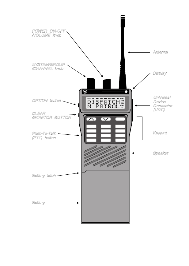
USER INTERFACE
The M-RK II operating controls are located on the
radio’s front, top and left panels. A 15-button keypad,
liquid crystal display (LCD) for radio status information,
microphone and speaker are on the front panel. The top
panel houses a rotary SYSTEM/GROUP/CHANNEL
knob, POWER ON-OFF/VOLUME control knob and a
protected red EMERGENCY button. An OPTION b utton,
CLEAR/MONITOR button and the Push-To-Talk (PTT)
button are all located on the left side panel. The Universal
Device Connector (UDC) is located on the right panel
and is used while programming the radio and for accessory connection.
The keypad is used for manual number entry for
individual calls, access to a telephone interconnect system, and activation of various EDACS or conventional
features such as menu selection or scan operations.
The display has two, eight-alphanumeric-character
lines used to show the operational mode of the radio. 15
status indicators, used to indicate various operating conditions such as transmitter on, channel busy, scanning,
or low battery, are located above and to the right side of
the character lines within the display. A back light illuminates the display and the keypad for nighttime use.
8
POWER ON-OFF
/VOLUME knob
SYSTEM/GROUP
/CHANNEL knob
Antenna
Display
OPTION button
CLEAR
/MONITOR BUTTON
Push-To-Talk
(PTT) button
Battery latch
Battery
Figure 1 - M-RK II Portable Radio
M-RK
Universal
Device
Connector
(UDC)
MNU
1
4
PVT
STS
7
PHN
✱
3
2
ADD6
5
DEL
9
MSG8
#
0
DISP
IND
Keypad
SCN
GRP
SYS
Speaker
9

SYSTEM/GROUP
/CHANNEL knob
POWER ON-OFF
/VOLUME knob
5
4
6
3
2
16
15
OFF
7
8
91
10
11
1214
13
MAX
Antenna
OPTION button
CLEAR
/MONITOR button
Push-T o-Talk
(PTT) button
Battery latch
Figure 2 - Top And Partial Left Panel Views
10
EMERGENY
button

BUTTONS AND KNOBS
This section describes the primary function of the
button and knob controls. Other functions associated
with these controls are detailed in later sections.
SYSTEM
/ GROUP
/ CHANNEL
KNOB
PO WER
ON-OFF
/ VOLUME
KNOB
Selects systems or groups/channels
(depending on programming). This is
a 16 - position rotary knob. See SYSTEM/ GROUP/CHANNEL SELECTION for details.
Applies power to the radio and adjusts the receiver’s volume. Rotating
the control clockwise out of detent
applies power to the radio. A single
alert tone sounds (if enabled through
programming) to indicate the radio is
operational.
Rotating the control clockwise increases the volume level. Minimum
volume levels may be programmed
into the radio to prevent missed calls
due to a low volume setting. While
adjusting the volume the display will
momentarily indicate the volume
level (i.e. VOL = 31). The volume
range is from a minimum programmed level of zero (displa y ed as
OFF in the display) up to 31 which is
the loudest level.
11

EMER-
GENCY
BUTTON
Provides single button emergency
channel access. See the EDACS and
conventional emergency sections for
more details.
OPTION
BUTTON
CLEAR/
MONITOR
BUTTON
PUSH-TO-
TALK BUT-
TON (PTT)
(1) Programmable per system.
(2) Perf orms the backspace function
during data entry. In Phone and Individual Call modes the OPTION button can be used to recall the last
phone number or radio ID entered.
Serves several purposes depending
on the operating mode. In trunked
mode, the CLEAR/MONITOR b utton
exits the current operation and removes all displa ys associated with it.
The radio and display then return to
the group receive state. In c onventional mode, pressing this button unmutes the receiver so activity on the
selected channel can be monitored.
When pressed and held for approximately 3 seconds, this button toggles
conventional channel decoding/encoding (Channel Guard, Digital
Channel Guard, T99) on and off if
programmed for the selected channel.
Enables the radio’s transmitter. Releasing PTT returns the radio to the
receive mode.
12

KEYPAD
The keypad layout is similar to a standard telephone
keypad but with three additional buttons at the top for a
total of 15 keys . In addition to numbers, most of the keys
have special functions and are labeled as such using a
symbol or abbreviated word describing its primary function. Numeric entry is a secondary function of the keys.
Each key is described below.
MNU
SYS
1
PVT
4
STS7
PHN
✱
Figure 3 - M-RK II Keypad
Primary function - changes the sys -
∧
tem or group/channel (depending on
∨
programming); secondary function changes to a selection for items
within a list. Press
creasing order,
ing order. To auto-ramp press and
hold the key .
GRP
2
5
MSG8
DISP0
∨
to scroll in decreas-
SCN
3
ADD6
DEL9
IND#
∧
to scroll in in-
13

14
MNU Primary function - accesses the
menu list. This is a list of additional
features that are not available directly from the keypad. See MENU
for details. Secondary function - activates a selected item within a list. After the menus list is accessed, select
∧
a menu item from the list via
or
and activate it with this ke y . Once activated, MNU continues its secondary function for activating a selected parameter setting until the radio returns to its normal receive
state. This is similar to an enter key .
SYS Used to directly access systems via
the keypad and to access system selection in increasing or decreasing
order, or to select a set (bank) of systems for SYSTEM/ GROUP/CHANNEL knob selection (depending on
programming). See SYSTEM/
GROUP/CHANNEL SELECTION
for details.
GRP Used to directly access groups via
the keypad and to access group selection in increasing or decreasing
order, or to select a set (bank) of
groups for SYSTEM/GROUP/
CHANNEL knob selection (depending on programming). See SYSTEM/
GROUP/CHANNEL SELECTION
for details.
∨

STS The Status key is used to send a pre-
programmed status message to the
EDA CS site .
SCN Toggles scan operation on and off.
When the radio is scanning, is
on and all groups or channels in the
scan list of the currently selected
system are scanned.
SCN
ADD
DEL
MSG The Message key is used to send a
PHN Used to place a telephone call
IND Used to call an individual or make an
DISP Inverts the display’s two alphanu-
Adds or deletes selected groups or
channels from the scan list of the currently selected system. See the
trunked and conventional scan sections for details.
pre-programmed status message to
the ED ACS sit e.
through the radio by selecting the
telephone interconnect special call
function. See Telephone Interconnect Calls for details.
all-call by selecting the individual call
special call function. See Individual
Calls for details.
meric character lines for viewing
from above; useful when the radio is
attached to the user’s belt.
15
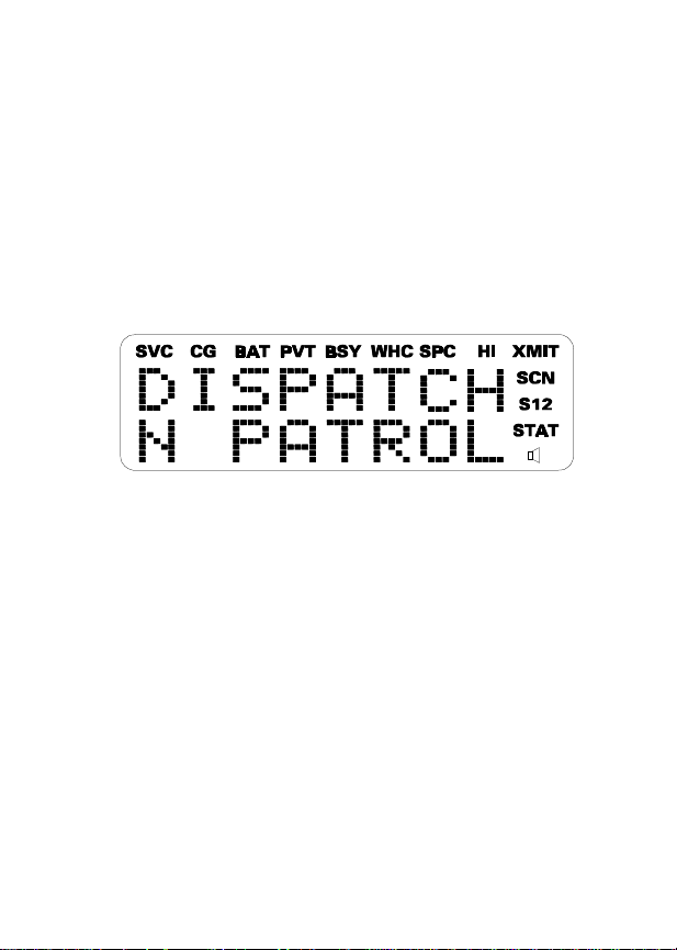
DISPLAY
The radio’ s display is shown belo w. T he two character
lines are used to display system, group and channel
names and also operational messages to the user. Each
line contains eight alphanumeric character blocks. The
15 status indicators are used to show the various operating conditions of the radio. If the display back-lighting
is programmed on, the display will illuminate for a short
period when any of the controls are operated.
Line 1
Line 2
Figure 4 - M-RK II Display
The two display lines can be inverted to permit easy
viewing if the radio is worn on a belt or placed into a
vehicular charger . Press DISP once to invert the character lines, press DISP again to return to the normal display.
Refer to the MENU section to change the display’s contrast.
16

Messages
During radio operation, various messages are displayed on either line one or line two. Typical messages
include control channel status information, such as system busy or call denied, or messages associated with the
radio’s operation, (i.e. volume or contrast adjust). These
messages are described below.
Message Name Description
QUEUED
SYS BUSY
DENIED
Call Queued
System Busy
Call Denied
Trunked mode
-
only. Indicates
the system has
placed the call in
a request queue.
Trunked mode
-
only. Indicates
the system is
busy, no channels are currently
available, the
queue is full or an
individual call is
being attempted
to a radio that is
currently transmitting.
Trunked mode
-
only. Indicates
the radio is not
authorized to op-
17

erate on the selected system
CC SCAN
WA SCAN
TALKARND
Control Channel Scan-Trunked mode
only. Indicates
the control channel is lost and the
radio has entered the Control
Channel Scan
mode to search
for the control
channel.
Wide Area Scan
Trunked mode
-
only. Indicates
the control channel is lost and radio has entered
the Wide Area
Scan mode to
search for a new
system (if enabled through
programming).
Talk-around
Conventional
-
mode only. Indicates the radio is
operating on
conventional
channels in talkaround mode (no
repeater).
18

*RXEMER*
Receive Emergency-Trunked mode
only . Indicates an
emergency call
is being received.
This message
will be flashing
on line two.
*TXEMER*
VOL = 31
LOW BATT
Transmit Emergency-Trunked mode
only . Indicates an
emergency call
has been transmitted. This message will be
flashing on line
two.
Volume Level
Indicates the cur-
-
rent volume le vel.
The volume level
display ranges
from OFF (silent)
to 31 (loudest).
Battery Low
-
Indicates the battery level is too
low for transmission. This message displays
when pressing
PTT and transmitting is disabled due to the
low battery condition.
UNKNOWN
Unknown ID
19

Trunked mode
-
only . Indicates an
individual call is
being received
by an unknown
radio ID. This bypasses when the
call is updated.
TX DATA
RX DATA
DATA OFF
DATA ON
20
Transmit Data
Receive Data
Data Off
Data On
Trunked mode
-
only. Indicates
when a data call
is being transmitted. Displayed on
line one.
-
Trunked mode
only. Indicates
when a data call
is being received.
Displayed on line
one.
-
Trunked mode
only. Indicates
when radio is in
data disable
state. Displayed
on line one.
Trunked mode
-
only. Indicates
when radio is
toggled to data
enable state. Dis-

played on line
one for two seconds.
KEY ZERO
PVT DIS
FRCD PVT
NO KEY #
Key Zero
Private Disabled
Forced Private
No Key Number
Indicates that
-
cryptographic
keys have been
erased from radio memory .
Indicates that the
-
group or channel
is not programmed for private mode operation.
Indicates that
-
group or channel
is pre-programmed for private mode operation and clear
mode is not possible.
-
Indicates that the
correct cryptographic key is not
loaded for the selected group or
channel.
21

Status Indicators
The 15 status indicators show the various operating
characteristics of the radio. The indicators show operating modes and conditions as follows:
SVC Trunked mode only .
ON - indicates the radio is in an EDACS
service area and is in communication with
the site controller via the control channel
(CC).
FLASHING - indicates the EDACS is in the
failsoft mode (if enabled through progr amming).
OFF - indicates the radio is out of range or
the control channel is not available.
CG Conventional mode only.
ON - indicates Channel Guard encode/decode is enabled on the selected conventional channel.
BAT ON - indicates the battery pack’s charge is
low and needs recharging.
PVT Private
22
ON - indicates the group or channel is enabled to receive encrypted messages.
FLASHING - indicates an encrypted
transmission is being received.

BSY Channel Busy -
In trunked mode:
ON - indicates the radio is transmitting
or receiving a call on the working channel.
FLASHING - indicates a call has been
queued.
In conventional mode:
ON - indicates a call is being received.
WHC Who Has Called (trunked mode only)
ON - indicates an individual call has been
received, but not responded to . The indicator turns OFF if the individual call mode is
entered, the system is changed or the radio is turned off and back on.
SPC ON - indicates the radio is in the special
call select/entry mode (Individual or Telephone Interconnect).
HI ON - indicates the selected group or chan-
nel is selected to transmit at high power .
OFF - indicates the selected group or
channel is selected to transmit at low
power.
XMIT ON - indicates the radio is transmitting.
When operating in a trunked system, the
radio may be programmed to automatically transmit (without pressing PTT) to
maintain digital communication with the
23

site controller. will turn on whenever the radio is transmitting.
SCN ON - indicates the scan mode is enabled.
S ON - indicates the selected group or chan-
nel is in the scan list.
1 ON - (conventional mode only) indicates
the selected channel is designated as the
priority-one scan channel.
2 ON - (conventional mode only) indicates
the selected channel is designated as the
priority-two scan channel.
XMIT
Speaker
Icon
UNIVERSAL DEVICE CONNECTOR (UDC)
The Universal Device Connector (UDC) provides
connections for external accessories such as a headset
or a speaker-microphone. When the radio is locked in a
vehicular charger/repeater the UDC provides the audio
and control connections between the radio and the vehicular charger/repeater. The UDC is also used to program and service the radio.
24
ON - (conventional mode only) indicates
that the selected channel has T99 decode
option enabled.

ALERT T ONES
The M-RK II radio also provides audible alert tones
or "beeps" to indicate the various operating conditions.
These alert tones can be enabled or disabled through
programming.
Call Originate
A short mid-pitched alert tone sounds after keying the
radio (Push-T o- T alk b utton is pressed). This indicates the
radio has been assigned a working channel or that the
radio is transmitting on a conventional channel and v oice
communication may begin immediately. In conventional
mode, this tone may be delayed after the PTT button is
pressed due to GE-STAR s ignalling (if enabled through
programming).
Autokey (Trunked Mode Only)
After being placed in queue or releasing the PTT
button prior to a working channel assignment, the site
calls the radio when a channel becomes available. At this
point, the radio automatically keys the transmitter
(autokey) for a short period to hold the channel. The radio
sounds a mid-pitched tone when it is clear to talk; immediately press the PTT button to keep the assigned channel.
Call Queued (Trunked Mode Only)
A high-pitched tone after pressing the PTT button
indicates the system has placed the call request in the
queue. The receiving unit(s) also hear the tones, indicat-
25

ing they will receive a call shortly . If the the PTT button is
released, the radio will autokey whenever a channel
becomes available (see Autokey).
System Busy (Trunked Mode Only)
Three low-pitched beeps will be heard if the radio is
keyed when the system is busy, if no channels are
available for sending the message, if the call queue is
full, or if an individual call is being attempted to a radio
that is transmitting. Releasing the PTT button and rek eying initiates a new channel request.
Call Denied (Trunked Mode Only)
If the radio is keyed and a low pitched tone is heard
then the radio is not authorized on the system that has
been selected.
Carrier Control Timer
If the programmed time for continuous transmission
is exceeded, five short high-pitched warning tones followed by a long low-pitched tone will be heard. The
transmitter will shut down shortly after hearing the alert,
interrupting communications. Release and re-key the
PTT button to maintain communications. This will reset
the carrier control timer and turn the transmitter back on.
Low Battery W arning
A low-pitched tone is heard and comes on
indicating that the battery voltage is low. The radio will
continue to receive and transmit.
26
BAT

Low Battery Alert (Transmit Lockout)
If the radio is keyed and a low-pitched tone or two
tones repeated until PTT or CLEAR button is pressed
(either conditions is pre-programmeable) is heard and
LOW BATT is displayed, the battery is discharged and
the radio will not transmit. The radio will still be able to
receive calls until the battery is discharged beyond the
point of operation, after which the battery will need to be
recharged to resume normal operation.
Key Press Alert
A short tone or "beep" sounds to indicate a key has
been pressed. A short low-pitched tone indicates no
action was taken because the key is not active in the
current mode.
OPERATION
TURNING ON THE RADIO
Rotate the POWER ON-OFF/VOLUME knob clockwise, out of detent to turn the radio on. (Ensure the
antenna and battery pack are properly connected prior
to power on.) A short beep (if enabled through programming) indicates the radio is ready for operation. The
display indicates, if programmed, the last selected system name on line one and the last selected group or
channel name on line two.
In the EDACS trunk ed en vironment, upon acquisition
of the control channel, will come on. If communi-
cation with the system’s control channel cannot be es-
SVC
27

tablished, will not turn on. This may occur if, for
SVC
example, the radio is out of range of the trunking site. It
may be necessary to move to another location or select
another trunking system to reestablish the control channel link for trunked mode operations.
SELECTION MODE RULES
Many operations require selection from a list such as
system, group or phone number. This selection process
∧, ∨,
is handled in the same manner for all lists.
MNU,
0-9, *, #, the OPTION button and the CLEAR/MONITO R
button are used during the selection process. The following example systems list is used to explain the process:
SYSTEM
1 NORTH
2 SOUTH
3 EAST
4 WEST
After entering a selection mode, the following generic
display format will appear.
XXXXXXXX
YYY =ZZZ
Line one shows the currently selected item name
(XXXXXXXX) from the list. Line two indicates the list
(YYY) that the selection is to be made from and the
number of the selected item (ZZZ) within the list. (In some
cases the information on lines 1 and 2 will be the opposite
of this example.) If SYSTEM 2 is the current selection,
the display appears as follows:
28

SOUTH
SYS = 2
Line one contains the current system name, SOUTH,
and line two, SYS = 2, indicates that selection is from the
system list and it is the second system within the list.
∧
A new system from the list is selected by using
∨
or by directly entering the system number with the
∧
numeric keys
and ∨ scroll through the list in increasing
and
and decreasing order respectively . In the pre vious exam-
∨
ple, pressing
selects the EAST system as shown in the
next display.
EAST
SYS = 3
The radio may be programmed to wrap around from
one end of a list to the other end or to stop at the ends.
To directly access a selection, enter the corresponding number (i.e. 4) followed by MNU to activate the
selection. Special calls (Individual Calls or Telephone
Interconnects) list selections or directly entered ID or
phone numbers are activated upon the press of the PTT
button and not MNU. The entered number is displayed
on line two as shown below. Line one shows the current
list being used for selection.
SEL SYS
4
29

If a mistake is made while entering the number, press
the OPTION button to backspace once and correct the
entry . If an inv alid number is entered, a short low-pitched
tone sounds when MNU is pressed.
To exit the selection mode, press the CLEAR/MONITOR button or w ait for the timeout. If the selection mode
is cleared while an entry is pending (i.e., numbers are
entered on line 2, but MNU has not been pressed), the
entry on line two will be disregarded and the previous
selection will remain active. If the timeout activates while
an entry is pending, the entry on line two will be selected
if it is within the valid range; if it is out of range the entry
on line two will be disregarded and the previous selection
will remain active.
NOTE
While in system, group or channel selection mode,
the radio continues to receive calls normally and
continues scanning if it is enabled. If a call is received
during the selection mode process the radio will return to the normal receive mode display. Continuing
with the selection process will return the display to the
same point in the selection process if the selection
mode time out has not yet expired. Any press of the
PTT button during the selection mode process will
initiate transmission and exit the selection mode.
MENU
The menu function accesses features that are not
available dir ectly from the keypad. The order and specific
number of menu items available is configurable through
30

programming. Upon radio power up, the menu item that
is at the beginning of the menu list will always be displayed first. Subsequent access to the menu function will
return the last menu item that was shown in the display.
∧, ∨
To enter the menu mode, press MNU. MNU,
, and
the CLEAR/MONITOR button are used during the selection process. All of the selection mode rules previously
detailed apply to the menu item selection process with
the exception of direct access. The radio will continue to
receive and transmit normally while in the menu function.
∧
A new item is displayed by using
and ∨ to scroll
through the list in increasing and decreasing order respectively. The displayed menu item is made active by
pressing MNU.
After entering the menu selection mode, the follo wing
generic display format will appear.
MENU
YYYYYYYY
Line one indicates the radio is in the menu selection
mode. Line two indicates the menu item (YYYYYYYY)
that is to be viewed or changed (some menu items
provide radio information and do not have changeable
parameters).
An example of the menu item selection process and
menu item parameter change is detailed below for the
backlight menu item.
PRESS: MNU
The menu mode is entered.
31

PRESS: ∧ or ∨ until the display shows:
MENU
BCK LGHT
PRESS: MNU
The backlight menu item is activated and the display
will be similar to the following:
BCKL=XXX
YYYYYYYY
Line one shows the active menu item and its current
parameter setting (XXX). Line two shows the currently
selected system or group name (YYYYYYYY).
The menu item’s parameter setting shown in the
∧
display can now be changed by using
through the list of parameter values. O nce the desired
setting is reached press MNU to store the value and
return the normal display. For menu items that display
∧
radio information pressing
of informational displays. The menu items are listed T able
1.
or ∨ will scroll through a list
or ∨ to scroll
NOTE
The TX POWER menu item, when selected,
toggles HI/LO power. It does not use
scroll nor an additional press of the MNU button.
∧
or ∨ to
32

Table 1 - Menu Item Information
FEATURE DISPLAY
Menu item:
Keypad Lock
Backlight Adjust
Contrast Adjust
Transmit Power
Select
Radio Revision
Information
KEY LOCK
Once selected:
LOCKED
Menu item:
BCK LIGHT
Once selected:
BCKL=
Menu item:
CONTRAST
Once selected:
CNTRST=
Menu item:
TX POWER
Once selected:
POWER=
Menu item:
REVISION
PARAMETER
SETTINGS
LOCKED
OFF, 1, 2, 3, 4,
5, 6, 7
1, 2, 3, 4, 5, 6,
7, 8
HI, LO
Informational
displays only
(see radio); no
user selectable
settings.
COMMENT
Locks the
keypad. To
unlock: press
and release
MNU
then
within 1 second
press the
OPTION button.
(NOTE: this
sequence is
also a short cut
to locking the
keypad.)
Selects the light
level for
backlighting.
Selects the
display contrast
level.
Selects high or
low power.
Selects the
information
display to view.
33

SYSTEM/GROUP/CHANNEL SELECTION
In the following description of SYSTEM/GROUP/
CHANNEL SELECTION, the term group is used for both
group and channel.
The M-RK II SYSTEM/GROUP/CHANNEL knob and
∧, ∨
the
pair are programmable for maximum flexibility. If
the SYSTEM/GROUP/CHANNEL knob is assigned to
∧, ∨
select groups, then the
keys are assigned to select
systems. If the SYSTEM/GROUP/CHANNEL knob is
assigned to select systems, then the
∧, ∨
keys are
assigned to select groups. System, group and channel
selection is the primary function for these controls.
Either systems or groups can also be selected by
entering the select mode and following the selection
mode rules described earlier. Only the selection as-
∧, ∨
signed as the primary function of the
pair will be
available f or this method of direct selection. For e xample,
∧, ∨
if system selection is the primary function of the
pair
then only the system select mode will be usable and
direct group select will be unavailable. The system select
or group select modes are entered by pressing SY S or
GRP, respectively, from the standard receive mode. Us-
∧, ∨
ing
after entering a particular selection mode in this
manner is the secondary function of these keys.
System Selection
Several methods, some of which depend on program-
ming, can be used to select a new system. These proce-
34

dures are presumed to be starting from the normal
receive display.
METHOD 1: If system selection is programmed to the
SYSTEM/GROUP/CHANNEL knob, select a system by turning the SYSTEM/GROUP/CHANNEL knob to the desired system number position (1-16). The
display registers the new system name on
line one. If the knob is mo v ed to a position
greater than the number of programmed
systems, the highest programmed system
will remain selected.
METHOD 2: If system selection is programmed as the
∧
primary function of
tem by pressing
and ∨, select a sys-
∧
or ∨ to scroll through the
system list. The display registers the new
system name on line one.
METHOD 3: Press SYS to enter the system select
mode and follow the selection mode rules
detailed earlier. If system selection is programmed to the SYTEM/GROUP/CHANNEL knob, direct access to systems will
not be available. Presses of
∧ or ∨
will
scroll through different sets of 16 systems
each (banks) if more than 16 systems are
programmed into the radio. The systems
within each bank are then selectable via
the SYSTEM/GROUP/CHANNEL knob
as described previously in METHOD 1.
35

Group And Channel Selection
Several methods, some of which depend on programming, can be used to select a new group or channel.
These procedures are presumed to be starting from the
normal receive display.
METHOD 1: If group selection is programmed to the
SYSTEM/GROUP/CHANNEL knob, select a group by turning the SYSTEM/GROUP/CHANNEL knob to the desired group number position (1-16). The
display registers the new group name on
line two. If the knob is moved to a position
greater than the number of programmed
groups, the highest programmed group
will remain selected.
METHOD 2: If group selection is programmed as the
∧
primary function of
by pressing
∧ or ∨
and ∨, select a group
to scroll through the
group list. The display registers the new
group name on line two .
METHOD 3: Press GRP to enter the group select mode
and follow the selection mode rules detailed earlier. If group selection is programmed to the SYSTEM/GROUP/
CHANNEL knob, direct access to groups
∧
∨
or
will not be available . Presses of
will
scroll through different sets of 16 groups
each (banks) if more than 16 groups are
programmed into the radio. The groups
within each bank are then selectable via
36

the SYSTEM/GROUP/CHANNEL knob
as described previously in METHOD 1.
TRUNKED MODE OPERATION
Digital trunking provides fast communication access
at all times, even during busy hours. In this mode the
operator selects a communications system and group
and the audio communication or working channel (WC)
is allocated through digital signalling with the site.
Receiving A Call
1. Turn on the radio by rotating the POWER ON-
OFF/VOLUME knob clockwise (out of detent). A
short aler t signal (if enabled through programming)
indicates the radio is ready to use.
2. The displa y shows the last selected or the power up
(depending on programming) system and group
names and indicates if the radio has acquired the
system control channel by turning on If the
radio is unable to obtain a control channel, line two
shows CC SCAN and will remain off.
SVC
SVC
3. Adjust the POWER ON-OFF/VOLUME knob to the
desired volume level.
4. Select the desired system and group. The display
indicates the current system and group names.
5. The radio is now ready to receive calls.
37

6. GROUP CALL - When the radio receives a group
call, it unmutes on the assigned working channel and
BSY
comes on. Line one shows GR followed by
the logical ID number (if received) of the unit sending
the message, or the associated name if the ID number is found in the individual call list.
7. INDIVIDUAL CALL - When the radio receives an
individual call (a call directed only to the user’s radio),
it unmutes on the assigned working channel and
turns on and . Line one shows ID followed by the logical ID number of the unit sending
the message, or the associated name if the ID number is found in the individual call list.
Responding to the call prior to the programmed
call-back time-out will automatically direct the call to
the originating unit. If the caller’s ID is not received,
UNKNOWN will display and there will be no call-back
hangtime.
Sending A Call
1. Turn on the radio and set the POWER ON-OFF/VOLUME knob to the desired volume level. S elect the
desired system and group.
BSY
WHC
2. Press and hold the PTT button. The radio will displa y
, the system and group names and perform
XMIT
the necessary signalling required to obtain a communication channel.
3.
When the working channel is assigned, and
are turned on and a short beep sounds indicat-
BSY
38
XMIT

ing that communication can begin. (NOTE: If two or
more tones, or a high pitched tone is heard, the
system may be busy and the call request has been
placed in queue or the request has been denied for
some reason. Refer to the ALERT TONES section
for more details.)
4. Hold the radio approximately three inches from the
mouth and speak in a normal voice into the micro-
∧
∨
and
phone (located between
on the keypad).
5. Release the PTT button when the transmission is
complete and listen for a reply.
Emergency Operation
The radio’s ability to declare an emergency, clear an
emergency , remain locked on an emergency system and
group, and the emergency audio and display freeze can
each be enabled or disabled through programming.
When an emergency is declared scanning will stop and
restarts only after the emergency has been cleared.
Receiving An Emergency Call
When receiving an emergency call from the selected
group and system, an alert beep is heard and
BSY
comes on. The message *RXEMER* flashes in the dis-
play on line two until the emergency condition is cleared.
Follow standard emergency procedures.
39

Declaring An Emergency Call
To send an emergency call to the selected system
and group (or on an optionally preprogrammed group),
proceed as follows:
1. Press and hold the red EMERGENCY button that is
on top of the radio in front of the antenna for approximately one second (this time is programmable and
therefore could be longer or shorter; check with the
system administrator). The radio will transmit an
emergency call request with the radio ID until an
emergency channel assignment is received.
2. When the working channel assignment is received,
the radio sounds a single beep (Autokey alert tone)
indicating it is ready for voice transmission.
*TXEMER* flashes on line two in the display until the
emergency is cleared.
3. Press PTT and speak into the microphone in a
normal voice . turns on.
4. Release PTT when the transmission is complete and
listen for a reply.
BSY
5. The emergency can be cleared by pressing and
holding the CLEAR/MONITOR button followed by
pressing the EMERGENCY button then releasing
both buttons.
40

Wide Area System Scanning
The M-RK II radio may be programmed f or wide area
system scan operation for multi-site applications. Upon
the loss of the currently selected system’s control channel, radios may be programmed to automatically scan the
control channels of other systems. If a new control channel is found, the radio will switch to the new system and
sound an alert tone.
The radio may also be programmed for priority system scan. A priority system may be assigned among the
systems programmed into the radio. Radios programmed
in this manner will check for the priority trunked system’ s
control channel at a programmable rate ranging from 1
to 16 minutes. This priority scan timer is reset each time
the PTT button is pressed or when a call is received. If
the priority system control channel is f ound, the radio will
automatically switch to the priority system.
ProSound
The radio may be pr ogrammed f or ProSound system
scan operation for multi-site applications. ProSound
scanning is an enhanced replacement for wide area
system scanning. This algorithm insures that the radio
continually receives high quality audio. When the selected system degrades to a pre-programmed level, the
radio changes to the new system and sounds a tone.
Should the control channel be lost completely, the radio
will scan the adjacent systems until a suitable one is
found.
41

Scanning T runked Gro ups
Groups which have been previously added to the
scan list on a per system basis may be scanned. Each
system’s group scan list is retained in memory when the
radio is turned off or when the battery pack is removed.
The following procedures outline scan operations for
trunked groups. See the conventional mode operating
procedures for specific procedures on conventional
channel scanning.
Adding Groups To A Scan List
1. With scan operation turned off select the desired
group to add to the selected system’s g roup scan list.
2.
Press ADD. comes on. Any group that is in a
system’s group scan list will show when it is the
selected group.
Deleting Groups From A Scan List
1. With scan operation turned off select the desired
group to delete from the selected system’s group
scan list.
2.
Press DEL. turns off. Any group that is not in a
system’s group scan list will not show when it is
the selected group.
A group can also be deleted from the scan list, if it is
not the currently selected channel, by pressing DEL
42
S
S
S
S

during scan operation while the radio is displaying the
unwanted group. The group will be deleted from the
system’s group scan list in the same manner as if done
using the steps above. Deletions done in this manner will
not remain deleted if the radio is turned off and then back
on.
Turning Scan On
1. Toggle scan operation on by pressing SCN. will
turn on when the radio is scanning.
2. When a group on the scan list receives a channel
assignment, the radio unmutes on the assigned
channel and comes on. Line one shows GR
followed by the logical ID number (if receiv ed) of the
unit sending the message, or the associated name
if the ID number is found in the individual call list. T he
group name displays on line two.
If the radio detects a call from the currently selected
-
group, it has priority and the radio will switch to the
selected group call.
The radio will continue scanning if a new group is
-
selected when scan is on.
Pressing the PTT button when scan is on will cause
-
the radio to transmit on the display ed group or to the
currently selected group (depending on programming).
BSY
SCN
43

Pressing ADD when scan is on will cause the radio
-
to recall the scanned group that was last received.
This group is recalled for period equal to the scan
hang time.
Turning Scan Off
Toggle scan operation off by pressing SCN. The radio
will resume operation on the selected group.
INDIVIDUAL CALLS
Receiving And Responding To An Individual Call
(Trunked Mode Only)
When the radio receives an individual call (a call
directed only to the user’s radio), it unmutes on the
assigned working channel and turns on and .
Line one shows ID followed by the logical ID number of
the unit sending the message, or the associated name if
the ID number is found in the individual call list. The radio
can be programmed to ring when an individual call is
received. If enabled, the ring begins five seconds after
the caller unkeys and will continue until the PTT button,
the CLEAR/MONITOR button or # is pressed.
BSY
WHC
If a response is made to the call prior to the programmed call-back time-out, the call will automatically be
directed to the originating unit. If a response is not made
before the call-back time-out, the radio will return to
normal receive display, but will remain on. If the
caller’s ID is not received, UNKNO WN will display for the
44
WHC

duration of the call and there will be no call-back hangtime.
To respond after the call-back time-out, press IND
while is on and the displa y will show the caller’ s ID.
WHC
The indi- vidual call selection mode is now active and the
selection mode rules apply . The caller can be responded
to by pressing the PTT button if no other selection is
made. Because the latest caller’s ID is stored in location
0 and the radio is now in the individual selection mode,
the caller can be selected directly by pressing 0 then
MNU. If the caller is selected in this manner proceed with
the call by pressing the PTT button.
Sending An Individual Call (Trunked Mode Only)
The following procedures describe how to initiate and
complete an individual call.
1. To select a previously stored individual, press IND
followed by
individuals. turns on. The selection mode rules
∧
or ∨ to scroll through the list of stored
SPC
apply. If the individual is not stored in this list but the
individual’s unit ID is kno wn, it can by entered directly
from the keypad. The last number entered directly
can be recalled by pressing the OPTION button.
2. Press the PTT button; the radio performs the necessary signalling to obtain a communication channel.
When the signalling is complete and the radio is clear
to transmit, turns on, turns off and the
XMIT
SPC
channel access tone sounds. Line one shows the
called individual’s name if found in the list of stored
45

individuals or ID followed b y the logical ID number of
the unit being called. The message *INDV* displays
on line two. Proceed with the message.
TELEPHONE INTERCONNECT CALLS
Receiving A Te lephone Inter c onnect Call (Trunked
Mode Only)
Receiving a telephone interconnect call is identical to
receiving an individual call. See the DTMF Overdial
Operation section if access to ser vices requiring "overdial" is needed. Ov erdial operations are av ailable f or an y
special call whether it is an individual call or a telephone
interconnect call.
Sending A T eleph one Inter co nnect Call (Trunked
Mode Only)
Use the following procedures to initiate and complete
a Telephone Interconnect call:
1. To select a previously stored phone number, press
PHN followed by
stored phone numbers. turns on. The selection
∧ or ∨
to scroll through the list of
SPC
mode rules apply. If the phone number is not stored
in this list but the phone number is known, it can by
entered directly from the keypad. If necessary, a
pause can be entered by pressing and holding 0-9,
*, or # until an underscore appears in the display . The
last entered phone number can be recalled by pressing the OPTION button.
46

2. Press and release the PTT button; the radio performs
the necessary signalling to obtain a communication
channel. When the signalling is complete and the
radio is clear to transmit, turns on, turns
off and the channel access tone sounds. Line one
shows the accompanying name if selected from the
list of stored numbers or the phone number if entered
directly . The message *PHONE* displays on line two .
The radio then automatically transmits the programmed number stored in the special call queue.
3. The telephone ringing will be heard. When someone
answers the phone, press the PTT b utton and speak
into the microphone. Release the PTT button to listen
to the callee. Unsuccessful interconnect signalling
returns the radio to the normal receive mode and the
number remains displayed until the special call is
cleared or the time-out expires or another group or
system is selected. Terminate a call by pressing the
CLEAR/MONITOR button.
XMIT
BSY
NOTE
The M-RK II radio is capable of simplex (one w ay)
conversation only. The callee can only hear the
radio if the PTT button is pressed (the radio is
transmitting) and the callee can only be heard
when PTT is released (the radio is receiving).
4. To terminate the call, momentarily press the
CLEAR/MONITOR button.
47

DTMF Overdial / Con vent ional Mode Telephone
Interconnect
Once the radio has established a connection to the
public telephone system, it may be necessary to "overdial" more digits to access banking ser vic es, answering
machines, credit card calls or other types of systems that
require DTMF (Dual-Tone Multi-Frequency) access digits. Overdial operation can also be used to initiate a
telephone interconnect call via DTMF signalling if a dial
tone has already been accessed on the system. This is
the method that is used for making a telephone interconnect call while operating in the conventional mode but will
also function in trunked mode if a dial tone is directly
accessible. Telephone numbers and other number sequences for overdialing can be stored in the phone list
when programming the radio or stored by the oper ator in
the first ten phone list entries. These numbers are accessed by pressing * then following the selection mode
rules.
The following steps are required to dial these numbers:
1. Follow the procedure in Sending A Telephone Inter-
connect Call (Trunked Mode Only) to establish a
connection to the telephone system or consult the
system administrator for the procedure to access a
dial tone on the trunked or conventional system.
2. Overdial numbers are transmitted using either
method below:
METHOD 1: Press and hold PTT while entering the
overdial number sequence from the key-
48

pad. This method sends DTMF tones during individual, telephone interconnect,
trunked group or conventional channel
calls. Anytime the PTT button is pressed
and held, the keypad is enabled f or DTMF
entry .
METHOD 2: Press * to enter the overdial select/entry
mode and follow the selection mode rules
to call up a stored number from the phone
list or to directly enter the overdial digits.
SPC
turns on. Press PTT to send the
overdial sequence once. If the number
needs to be transmitted again it must be
selected or entered again (this prevents
unwanted numbers from being sent the
next time the PTT b utton is pressed during
the call).
This overdial select/entry mode remains
active until the call is dropped, cleared, or
MNU is pressed. The overdial select/entry
mode can be re-entered if the call is still
active by pressing *.
PROGRAMMABLE ENTRIES
Individual call ID numbers, telephone numbers and
other number sequences for overdialing are stored in the
special call lists when programming the radio. The first
ten entry locations of these lists can be changed by the
radio operator . T he ke ypad is used when adding, changing and storing numbers in these entry locations.
49

Use the following procedure to store a number in one
of the first ten entries of a special call list:
1. Press IND or PHN to enter the individual call list or
the phone call list. turns on. The selection mode
SPC
rules apply.
2.
Scroll through the list using
∧
or ∨ until one of the first
ten entries is reached. NO ENTR Y is displa yed if the
location is empty.
3. Enter the desired number. If necessary, a pause can
be entered by pressing and holding 0-9, *, or # until
an underscore appears in the display. The individual
call list entries will accept up to 5 digits. The phone
call list entries accept a combination of up to 31 digits
and pauses.
4. Press and hold MNU until the display changes indicating that the number has been stored.
5. Repeat the steps above if the number stored in an
entry location needs to be changed.
CONVENTIONAL MODE OPERATION
The radio functions in the conventional mode when
using conventional communications channels (nontrunked). Each channel consists of a preset frequency
pair for transmit and receive during repeater operation,
or a single frequency for both tr ansmit and receive during
talk-around (no repeater) operation. To use this mode,
the operator selects a conventional system which includes one or more conventional channels. Each conven-
50

tional channel may have one or more features, such as
Channel Guard, programmed when the channel is selected.
The CLEAR/MONITOR button unmutes the receiver
so activity on the selected channel can be monitored.
When pressed and held for approximately 3 seconds this
button toggles conventional channel decoding (Channel
Guard, Digital Channel Guard or T99) on and off if
programmed for the selected channel.
Receiving A Call
1. Turn on the radio by rotating the POWER ON-
OFF/VOLUME knob clockwise (out of detent). A
short aler t signal (if enabled through programming)
indicates the radio is ready to use.
2. Adjust the POWER ON-OFF/VOLUME knob to the
desired volume level.
3. Select the desired conventional system and channel.
The display indicates the current conventional system and channel names.
4. The radio is now ready to receive calls.
5. When the radio receives a call (and the correct
encoding is decoded, if programmed and enabled),
it unmutes on the channel and comes on.
BSY
51

Sending A Call
1. Turn on the radio and set the POWER ON-OFF/VOLUME knob to the desired volume level. S elect the
desired conventional system and channel.
2. Ensure that the channel is not busy by pressing the
CLEAR/MONITOR button to momentarily disable
any channel decoding and unmute the receiver or
observe the display for the absence of . If the
BSY
Channel Busy Lockout feature is programmed f or the
selected channel, the radio will not transmit when the
channel is busy.
3. Press and hold the PTT button. The radio will displa y
XMIT
and a short beep sounds (if programmed)
indicating that communication can begin.
4. Hold the radio approximately three inches from the
mouth and speak in a normal voice into the micro-
∧
phone (located between
and ∨ on the keypad).
5. Release the PTT button when the transmission is
complete and listen for a reply.
Emergency Operation
If enabled, GE-STAR emergency signalling can be
transmitted when operating in the conventional mode.
This GE-ST AR signalling will transmit 5 times with a dela y
between each transmission. To send an emergency call
on the selected conventional system and channel (or on
an optionally preprogrammed conventional emergency
system and channel), proceed as follows:
52

Press and hold the RED EMERGENCY button that is
on the top of the radio in front of the antenna for
approximately one second (this time is programmable
and therefore could be longer or shorter ; check with
the system administrator). The radio displays
and proceeds to transmit the pre-programmed GESTAR emergency signalling sequence.
GE-STAR is programmed to transmit in one of the
following methods:
METHOD 1: GE-STAR is transmitted on the selected
channel. If the channel is changed the
emergency signalling will continue to be
transmitted on the newly selected channel.
METHOD 2: Same as METHOD 1 b ut the radio will lock
on to the currently selected channel. Any
attempts to change the channel will be disabled.
METHOD 3: GE-STAR is transmitted on a pre-pro-
grammed conventional emergency system and channel regardless of the selected channel. In this case the selected
channel is available f or voice transmission
and the radio will periodically change to
the pre-programmed emergency system
and channel to send the emergency signalling and then change back to the selected channel.
XMIT
53

METHOD 4: Same as METHOD 3 b ut the radio will lock
on to the pre-programmed emergency
system and channel. Any attempts to
change the channel will be disabled.
The emergency state can be cleared by turning the
radio off and then back on.
Using 5-Tone Signalling for Emergency Declaration
If 5-Tone signalling is defined for emergency declaration in place of GE-STAR emergency signalling, a preprogrammed tone sequence will be transmitted instead
of the GE-STAR sequence. This emergency declaration
functions as the GE-STAR emergency in all other respects.
T one Encode Transmission
In conventional mode two keys can be defined to be
tone encode triggers. If one of the pre-progr ammed tone
encode triggers is pressed, a pre-programmed tone sequence will be transmitted on the current s ystem and
E
channel. (See Emergency Operation if
is used.)
The XMIT indicator will light during tone transmission and
a beep will sound at the end of the transmission. If
enabled, audible side tones will be heard in the radio
speaker as well. If PTT is pre-programmed as one of the
triggers, the microphone will become active for voice
communication after the tone sequence is complete.
Tone encode will be transmitted with Channel Guard
if one is defined, and tones are always transmitted in
54

clear voice mode, even if the channel is set for digital or
private (see VOICE MODES). Digital or private voice
transmission will resume normally after the tone transmission.
Scanning Conventional Channels
Channels which have been previously added to the
scan list on a per system basis may be scanned. The
selected channel is scanned (if enabled through programming) whether or not it is in the scan list. Each
conventional system’s channel scan list is retained in
memory when the radio is turned off or when the battery
pack is removed.
The scan rate will vary depending upon the number
of channels in the scan list and whether or not the radio
is programmed to scan for channels with decoding enabled. Fewer channels will result in a faster scan rate. If
programmed for dual-priority scan operation, the priorityone, priority-two and the remaining scan list channels are
scanned. Once a signal is detected and the correct
encoded squelch signal is decoded (if programmed), the
radio receives the message and displays the received
scan channel. At the same time, scanning continues on
the priority-one and priority-two channels. Should the
priority-one or priority-two channel carrier, regardless of
encoded squelch decoding, be detected while a non-priority channel is being received, the display name is
updated, or comes on and the received channel is
switched to the priority channel. Scanning of the priorityone channel will continue if a message is being received
on the priority-two channel.
1 2
55

The following procedures outline scan operations for
conventional channels.
Adding Groups To A Scan List
1. With scan operation turned off select the desired
channel to add to the selected conventional system’ s
channel scan list.
2.
Press ADD. comes on. This sets the selected
channel for non-priority scanning. A second press of
ADD sets the channel for priority-two scanning and
2
comes on. An additional press of ADD sets the
channel for priority-one scanning and comes on.
If the priority-one or priority-two channels are already
set and a new channel is then assigned as the
priority-one or priority-two channel, the previously
assigned priority channel with change to non-priority
scanning. The priority setting selection sequence is
set and stops at priority-one therefore the channel
must be deleted from the scan list by pressing DE L
before the channel is set to a previous priority setting.
Any channel that is in a system’s channel scan list
will show , or when it is the selected channel.
Deleting Groups From A Scan List
1. With scan operation turned off select the desired
channel to delete from the selected conventional
system’s channel scan list.
2.
Press DEL. , or turns off. Any channel that
is not in a conventional system’s channel scan list
56
S
1
S 2 1
S 2 1

will not show , or when it is the selected
channel.
A channel can also be deleted from the scan list, if it
is not the currently selected channel, by pressing DEL
during scan operation while the radio is displaying the
unwanted channel. The channel will be deleted from the
conventional system’s channel scan list in the same
manner as if done using the steps above. Deletions done
in this manner will not remain deleted if the radio is turned
off and then back on.
Turning Scan On
S 2 1
1. Toggle scan operationon by pressing SCN.
will turn on when the radio is scanning.
2. When a channel on the scan list receives a channel
assignment, the radio unmutes on the assigned
channel, comes on and the received scan
channel is displayed.
The radio will continue scanning if a new channel is
-
selected when scan is on.
Pressing the PTT button when scan is on will cause
-
the radio to transmit on the displayed channel or to
the currently selected channel (depending on programming).
Pressing ADD when scan is on will cause the radio
-
to recall the scanned channel that was last received.
BSY
SCN
57

This group is recalled for a period equal to the scan
hang time.
Turning Scan Off
Toggle scan operation off by pressing SCN. The radio
will resume operation on the selected channel.
AEGIS AND VOICE GUARD OPERATION
VOICE MODES
Each system (trunked or conventional) in the radio is
programmed for either Aegis or Voice Guard communications. Aegis programmed systems have three (3) different voice modes: clear (analog), digital and private.
Voice Guard systems have two (2) voice modes: clear
(analog) and private. The voice modes are programmed
on a per-group basis within each trunked system and on
a per-channel basis within each conventional system. A
radio must be equipped with the encrypt/decrypt option
before it will operate in Aegis or Voice Guard modes.
58

TRANSMIT/RECEIVE MODE COMPATIBILITY
FOR AEGIS OPERATION
GROUP/CHANNEL
PROGRAMMING
(TRANSMIT)
CLEAR Yes No No
DIGITAL Yes Yes No
PRIVATE Yes No Yes*
CLEAR
RECEIVE
DIGITAL
RECEIVE
PRIVATE
RECEIVE
TRANSMIT/RECEIVE MODE COMPATIBILITY
FOR VOICE GUARD OPERATION
GROUP/CHANNEL
PROGRAMMING
(TRANSMIT)
CLEAR Yes No
PRIVATE Yes Yes*
CLEAR
RECEIVE
PRIV ATE
RECEIVE
*assumes the proper cryptographic key is loaded
NOTE
Conventional Aegis or encrypted channels
require Channel Guard on the channel to operate
correctly.
59

Clear Modes
Aegis clear and Voice Guard clear modes are identical voice modes in which the radio transmits and receives
only clear (analog) voice signals. These analog signals
are non-digitized and non-encrypted. Clear mode transmissions can be easily monitored by unauthorized persons. Groups or channels programmed for clear operation cannot transmit or receive Aegis digital or private
messages.
Aegis Digital Mode
Aegis digital mode allows the radio to transmit and
receive digitized voice signals. Aegis digital signals provide improved weak signal perf ormance and they cannot
be easily monitored with a standard receiver . Groups and
channels programmed for Aegis digital operation transmit only digital signals. Private calls cannot be received
or transmitted when the radio is in the Aegis digital mode
because the radio does not know the cryptographic key
used. Message trunked group calls and individual calls
will be answered back in the mode they were received,
assuming the call or hangtime is still active. Individual,
phone, all and emergency calls will be transmitted clear
if digital mode is disabled or inoperative.
1. If receiving an analog message trunked call, the
radio will respond in analog mode during the hang
time on the working channel.
2. If receiving an analog I-Call, the radio will respond in
analog mode during the hang time.
60

3. When using the "WHC" feature to respond to an
I-Call (after the hang time has expired), the call will
be transmitted in the mode defined by the system
mode as programmed for the current system if the
ID being called is not in the I-Call list. If the ID is in
the I-Call list, then the call will be transmitted as
defined by the I-Call mode programmed in the list for
that ID.
DTMF
The overdial and hot ke ypad f eatures f or transmitting
DTMF tones are not available while in the Aegis Digital
Mode.
Error Messages
If either of the following error messages is displayed,
the radio was either programmed incorrectly or needs
servicing:
DSP ERR
ERR=xxxx
DSP ERR
Power Up Only
If the Aegis circuit board is not responding, the f ollowing error message will be displayed and the radio needs
servicing:
HARDWARE
ERR= 30
61

Aegis Private And Voice Guard Private Modes
The Aegis private and Voice Guard private modes
allow the radio to transmit encrypted messages and
receive clear or private transmissions. The radio will
transmit private if the group/channel is programmed for
private operation and forced operation is pre-programmed. If autoselect operation was pre-programmed
and the radio is in private mode, the radio will transmit in
the mode of the received call if the hang time is active. If
no hang time is active, the radio will transmit private.
Aegis transmissions cannot be received by a radio set
to receive a Voice Guard transmission. Accordingly, a
V oice Guard transmission cannot be receiv ed by a r adio
set to receive an Aegis transmission.
Cryptographic keys are transferred to the radio using
a cryptographic Keyloader. Up to seven (7) different
cryptographic keys, numbered 1-7, can be transferred
from a Keyloader and stored in the radio. An individual
key is automatically selected on a per-group/channel
basis according to the radio’s programming. Groups and
channels within Aegis systems can be programmed for
keys 1-7. Groups and channels within Voice Guard systems can be programmed for keys 1-7. Up to 8 banks of
7 keys can be stored for Aegis (DES and VGE) systems
and up to 4 banks of 7 keys for V oice Guard systems. The
bank is specified per system.
DES radios require a DES Keyloader (Option V4025
with software Version 3.N or later). VGE radios require a
VGE K eyloader (Option V4028 with software V er sion 2.N
or later).
62

When operating on a group or channel programmed
for private mode, all transmissions will be private transmissions and the radio will receive clear and private
signals. The status flag in the display turns on when
the private mode is enabled. If the selected group or
channel is programmed for autoselect capability, the
mode may be toggled between private and clear with the
PVT button. Radios programmed for forced private operation do not allow a change of the transmit mode;
therefore, the PVT button has no effect.
T ransf erring Keys Int o The Radio
The following procedure outlines basic key transferring steps.
1. Turn the radio off.
2. Plug the modular connector of the Keyloader cable
into the Keyloader modular jack.
3. Connect the Keyloader cable to the UDC on the
radio.
4. Press the PWR button on the Keyloader and wait f or
the Keyloader to display "MASTER MODE".
PVT
5. Press the TRN button on the Keyloader . If necessary,
select a different cryptographic key to be tr ansferr ed
into the radio.
63

6. Turn the radio on. The top line on the radio display
will read "KEY LOAD" and the second line will read
"BANK = N" where N= keybank number . Press the
or ∨ button to select the ke ybank. A beep will indicate
that the Keyloader is connected.
7. Press the EXE button on the Keyloader to transfer
the key. The Keyloader will display "GOOD 1.x
TRANSFER" where "x" is the selected cryptographic
key number.
8. Disconnect the cable from the radio’ s UDC. The radio
will change to the selected group or channel as
indicated in the display.
Displaying The Currently Used Crypto graphic K e y
Number
To display the cryptographic key currently in use for
either the system encryption key (for special call such as
individual, phone, all, agency or fleet) or the group/channel key (for group or conventional calls), perform the
following procedure:
1. Press the MNU button.
∧
2.
Use the
3.
Then use the
∧
or ∨ button to select "DISP KEY".
∧
or ∨ button to toggle between dis-
playing the system key or the group/channel key.
64

ENCRYPTION KEY
DISPLAYED
MESSAGE DISPLAYED
System
Group/Channel
"SYS KEY"
"KEY = 1"
"GRP KEY"
"KEY = 2"
Key Zero
All cryptographic keys can be zeroed (erased from
radio memory) by pressing the MONIT OR/CLEAR button
and while still pressing this button, press and hold the
OPTION button. Press both buttons for 2 seconds. A
series of beeps will begin at the start of this 2 second
period and then switch to a solid tone after the keys have
been zeored. The display will indicate "KEY ZERO"
If the cryptographic key(s) are zeroed, one or more
keys must be transferred from the Keyloader into the
radio before private communications may continue.
Private Operation
Receiving An Encrypted Call
When receiving, the radio automatically switches between clear or private operation. If the transmission being
received is an encrypted transmission, it will be decrypted, the status flag will flash, the receiver will
PVT
unsquelch and the message will be heard in the speaker.
For this to occur, the selected group or channel must be
programmed for private operation and the correct cryptographic key must be loaded into the radio.
65

Transmitting An Encrypted Call
1. Select the desired group or channel.
2. Place the radio in private mode b y pressing the PVT
button. When private mode is enabled, the
status flag will be on.
If the last state of the radio was private mode, the
private mode will be enabled on power up. Also the
private mode will be enabled if forced operation has
been programmed in the radio.
If a group or channel is not programmed for private
mode operation, "PVT DIS" will be displayed if an
attempt is made to enable private transmit mode. It
is not possible to operate on this group/channel in
private mode.
If the radio is programmed for f orced private transmit
operation, "FRCD PVT" will be displayed if an attempt is made to disable private transmit mode. It is
not possible to transmit on this group/channel in
clear mode.
If the radio does not have the correct encryption key
loaded, "NO KEY #" will be displayed and the call will
not be transmitted.
PVT
3. Continue with standard transmission procedures. A
private mode access tone will be heard when the
PTT button is pressed.
66

Scanned Group Calls
Receiving a scanned group call is the same as receiving a selected group call. During the scan hang time, if
the radio was programmed for autoselect, it will transmit
back in the same mode it received the call. F or e xample,
if a clear group is entered in the scan list, it will only
receive clear calls. If the same group was available in
private and entered in the scan list, it can receive clear
and private calls, provided autoselect was programmed
in the radio. The user can select transmitting on the
scanned or selected group. If a group is entered in the
scan list more than once and in different modes (clear,
digital, private), only the first occurrence of the gr oup will
be used.
PORTABLE DATA
The M-RK radios when operating in the EDACS configuration permit either voice or data calls to be transmitted or received. The radio can handle only one type of
call at a time; however, selection of either data or voice
is selected transparently by the operator through normal
usage of the radio. Data communications is not supported in the conventional mode.
The radios can be connected to Mobile Data Terminals (MDT) or to a host computer. Any RS-232 compatible device that supports the Radio Data Interface (RDI)
protocol (Version 1.91 or greater) may be connected to
the radio. Support for MDT’s or host computers is a
programmable option per radio. Additionally, radios programmed for host computers may also be programmed
for data only operation (no voice calls transmitted or
received).
67

DISPLAYS
The following will be displayed in the display during
the various states of data mode of operation.
TX DATA
RX DATA
DATA OFF
DATA ON
DATA OFF OPERATION
The radio can be placed in the data disabled state by
any of the following methods. When the data state is
disabled, the display shows "DATA OFF" on the top line.
Declaring an emergency (not to be used unless an
•
actual emergency condition exists). Alert tone will
sound.
Pressing the OPTION button (if pre-programmed for
•
no data key). Alert tone will sound.
Displayed on top line of display when the
radio is transmitting a data call.
Displayed on top line of display when the
radio is receiving a data call.
Displayed on top line of display when the
radio is in the data disabled state.
Displayed for two seconds on top line of
display when the radio is toggled to the
data enabled state.
Pressing the no data (ND) key (pre-programmed).
•
68

DATA ON OPERATION
The data state is enabled by one of the following
(depending on how it was disabled). "DATA ON" will be
displayed on the top line in the display for two seconds
then the display returns to normal.
Pressing the no data (ND) key toggles data state on
•
or off.
Clearing an emergency but valid only if emergency
•
caused data off operation.
EXITING DATA CALLS
Under normal conditions, the radio enters the scan
lockout mode and returns to the control channel after
completion of a data call (transmit or receive). If, during
a data call,one of the following conditions occurs, the
data call is immediately terminated and the radio performs the desired function:
PTT activated.
•
Emergency declared by pressing the pre-pro-
•
grammed emergency button.
A group or system change.
•
69

SCAN LOCKOUT MODE
Following the transmission or reception of a data call,
if scan is enabled, scanning will stop temporarily [two
independent pre-programmed times (after receive data
call and after transmit data call)]. During this time the
scan indicator will flash to indicate that scan is enabled
but temporarily suspended. This mode is normally exited
when the pre-programmed time expires; however, the
following actions will terminate the scan lockout mode
before the timeout is completed.
The CLEAR button is pressed.
•
The PTT is pressed.
•
A group or system change.
•
Entering phone call mode.
•
Entering individual call mode.
•
A new emergency assignment has been received.
•
An emergency declared or cleared.
•
Receiving an individual or phone call.
•
Receiving Agency, Fleet or System All Call.
•
Pressing the SCN button to turn scan on or off.
•
70

DATA LOCKOUT MODE
During the voice call scan hang time (pre-pro-
grammed) the radio will not receive data calls.
STATUS/MESSAGE OPERATION
STATUS OPERATION
Status operation permits the transmission of a pre-
programmed status condition to the EDACS site.
To send a status condition, press the STS key then
press one of the number keys (0-9) to select the pre-programmed status. If no status has been programmed for
the selected number key, the radio will display
"NO ENTRY". A valid selection will permit the status te xt
to appear in the display f or a pre-progr ammed time. After
the time-out expires or the MNU key has been pressed
(the MNU key will override the time-out period), the status
is selected and will be transmitted to the site or stored in
the radio memory where it can be polled by the site at a
future time. If the site does not receive the status properly ,
the radio will sound a low pitched tone.
If an incorrect status was selected or the incorrect
number key was pressed, the status can be changed
during the pre-programmed time-out period by pressing
another number key. The status selection can also be
cancelled by pressing the CLEAR button prior to the
time-out period.
To view the currently selected status after it has been
transmitted, press the STS key and then the CLEAR
71

button prior to the time-out period. If the status was not
sent successfully to the site, the text associated with the
status will flash in the display.
The radio can also be pre-programmed to redesignate the keypad b uttons f or ST0 thru ST9 to send status
condition. In this configuration the radio status operation
will operate as previously described except the STS key
is not required.
MESSAGE OPERATION
Message operation permits the transmission of a
pre-programmed message text to an EDACS site.
To send a message, press the MSG key then press
one of the number keys (0-9) to select the pre-programmed message text. If no message text has been
programmed for the selected number key, the radio will
display "NO ENTRY". A valid selection will permit the
message text to appear in the display for a pre-programmed time. After the time-out expires or the MNU key
has been pressed (the MNU ke y will override the time-out
period), the message text is selected and will be transmitted to the site. If the site does not receive the message
properly, the radio will sound a low pitched tone.
If an incorrect message text was selected or the
incorrect number key was pressed, the message te xt can
be changed during the pre-programmed time-out period
by pressing another number key. The message text selection can also be cancelled by pressing the CLEAR
button prior to the time-out period.
72

To view the currently selected message text after it
has been transmitted, press the MSG key and then the
CLEAR button prior to the time-out period. If the message
text was not sent successfully to the site, the text associated with the message will flash in the display.
EDACS CONVENTIONAL P1 SCAN
This feature permits the radio user to scan a pre-programmed conventional system and channel as a Priority
1 (P1) channel while the radio is selected for EDACS
trunked system. If activity is detected on the conventional
P1 channel, the radio will unmute and remain on this
conventional channel for the programmable hang time.
The radio must be pre-programmed to designate a
key for scan on/off operation.
DYNAMIC REGROUP OPERATION
Dynamic group operation permits multiple talk groups
(up to eight) to be added to a radio via the system
manager. The radio must be pre-programmed to respond to regrouping. Dynamic regrouping will not be
activated in a radio until an activation message is sent by
the system manager. Each radio that receives and acknowledges the regrouping instructions is successfully
regrouped.
Pressing and holding the CLEAR/MONITOR button
for 2.5 seconds toggles the user into and out of the
dynamic regroup groupset. A double beep will sound for
entry or exit. The display will indicate "REGRP_0x"
where "x" is a digit of 1 to 8 indicating the group when
73

dynamic regroup has been enabled by the user. If the
radio is in dynamic regroup and the user selects a group
that has not been regrouped, the display will show "NO
ENTRY". The radio will be prevented from transmitting
and receiving calls in this condition except for scanned
groups.
EMERGENCY OPERATION
If the pre-programmed groupset on the currently selected system contains an EMER/HOME group and the
radio is in dynamic regroup, the radio will declare the
emergency on the currently selected dynamic group
group.
MACRO KEY OPERATION
Macro key operation permits the user to accomplish
a series of key strokes with a single "macro" key stroke.
Up to ten (10) macro keys can be defined, each capab le
of executing up to twenty (20) key strokes, to any pushbutton input (i.e., keypad buttons, OPTION button, etc.).
Each macro key can be pre-programmed to activate
when pressed or when released.
A macro key may also be pre- programmed to change
the key stroke sequence the next time the macro key is
activated. A macro key function will be aborted if the user
changes a button or knob position.
For detail operation and assignment of macro keys,
contact your communications supervisor or administrator.
74

OPERATING RULES AND REGULATIONS
Two way FM radio systems must be operated in
accordance with the rules and regulations of the Federal
Communications Commission (FCC). As an operator of
two way radio equipment, the user must be thoroughly
familiar with the rules that apply to the intended type of
radio operation. Following these rules will help to eliminate confusion, assure the most efficient use of existing
radio channels, and result in a smoothly functioning radio
network.
When using the radio, remember these rules:
1. It is a violation of F CC rules to interrupt an y distress
or emergency message. In conventional mode the
radio operates in much the same wa y as a telephone
"party line" therefore always listen to mak e sure that
the line is clear--that no one else is on the air--before
sending any messages. If someone is sending an
emergency message--such as reporting a fire or
asking for help in an accident--KEEP OFF THE AIR!
2. Use of profane or obscene language is prohibited by
Federal Law.
3. It is against the law to send false call letters or a false
distress or emergency message.
4. The FCC requires that conversations be brief and
confined to business. To sav e time , use coded messages whenever possible.
5. Using the radio to send personal messages (except
in an emergency) is a violation of FCC rules. Only
75

those messages essential for the business oper ation
may be sent.
6. It is against the Federal law to repeat or otherwise
make known anything overheard on the radio. Conversations between others sharing a communications channel must be regarded as confidential.
7. The FCC also requires that the caller be identified at
certain specific times by means of call letters. Refer
to the rules that apply to the particular type of operation for the proper procedure.
8. No changes or adjustment shall be made to the
equipment except by an authorized or certified electronic technician.
OPERA TING TIPS
The following conditions tend to reduce the effective
range of two-way radios and should be avoided whenever possible.
Operating the radio in low areas of terrain or while
•
under power lines or bridges.
Operating the radio inside of a vehicle or in a metal
•
or steel framed building unless using an outside
antenna.
Obstructions such as mountains or buildings be-
•
tween the sending and receiving parties.
76

In areas where transmission or reception is poor,
some improvements may be obtained by insuring that the
antenna is vertical. Moving a fe w yards in another direction or moving to a higher elevation may also improve
communication.
BATTERY PACKS
CHARGING THE BATTERY PACK
After receiving a new rechargeable battery pack from
the factory , it should be fully charged before placing it into
service. This also applies to rechargeable batteries that
have been stored f or long periods. When the battery pack
requires charging the radio will signal the operator with
an alert tone and will turn on.
Chargers are available with nominal charge times of
1 hour (rapid) and 14 hours (standard). Combinations
include single and multi-position, standard and rapid
charge units. In addition, the vehicular chargers/repeaters simultaneously charge the battery packs while the
radio is operating. For specific instructions refer to the
applicable charger Operating Manual.
BAT
The rechargeable batteries used with the radio can
develop a reduced capacity condition sometimes called
the "Memory Effect". This condition can occur when a
battery is continuously charged for long periods or when
a regularly performed duty cycle allows the battery to
expend only a limited portion of its capacity. The battery
pack may show a sev ere decrease in its ability to deliver
full capacity for an extended period. Any rechargeable
77

battery pack showing signs of reduced capacity should
be returned to a qualified service center for inspection.
RECHARGEABLE BATTERY PACK DISPOSAL
The product that you have purchased
contains a rechargeable battery. The
battery is recyclable. At the end of its
useful life, under v arious state and local
laws, it may be illegal to dispose of this
battery into the municipal waste stream.
Check with your local solid waste officials for details in your area for recycling options or proper
disposal. Call Toll Free 1-800-822-9362 for information
and/or procedures for returning rechargeable batteries in
your state.
INSTALLING THE BATTERY PACK
1. Ensure the POWER ON-OFF/VOLUME knob is in
the OFF (detent) position.
2. Align the battery pack grooves with the battery
mounting plate rails on the bottom of the radio.
3. Insert the rails into the grooves and slide the battery
toward the battery latch until the battery latch clicks
into place.
REMOVING THE B ATTERY PACK
1. Ensure the POWER ON-OFF/VOLUME knob is in
the OFF (detent) position.
78

2. Release the battery latch by pushing it upward toward the top of the radio.
3. Remov e the battery pack by sliding it a w ay from the
battery latch until it separates from the radio.
Figure 5 - Installing And Removing The Battery Pack
INTRINSICALLY SAFE USAGE
Selected portable radios with appropriate factory installed F4 Options are certified as Intrinsically Safe by
the Factory Mutual Research Corporation. Intrinsically
Safe approval includes Class l, II, Ill, Division 1 hazardous locations in the presence of Groups C, D, E, F and
G atmospheres. Non-Incendive approval includes Class
79

I, Division 2 hazardous locations in the presence of
Groups A, B, C and D atmospheres.
Hazardous locations are defined in the National Electrical Code. Useful standards NFPA 437A and NFPA
437M for the classifications of hazardous areas can be
ordered from the National Fire Protection Association,
Batterymarch Park, Quincy, MA 02269.
BATTERY PACKS
Only battery packs identified with a green latch shall
be used with a portable radio that is rated and labeled as
Factory Mutual Intrinsically Safe. Use of nonspecified
battery packs voids Factory Mutual approval. T he following battery pack options are approved for use in intrinsically safe radios:
PKPA5X Rechargeable Battery Pack, Extra
High Capacity (Tall Case)
PKPA5W Rechargeable Battery Pack, High
Capacity (Short Case)
ACCESSORIES
The accessories that follow are approved f or use with
intrinsically safe radios. Use of accessories other than
those listed voids Factory Mutual approval.
PKAE3A Speaker/Microphone
PKAE1C Speaker/Microphone/Antenna
PKAC1J Earpiece Kit
PKHC1C Belt Clip
80

PANC1B Antenna, 136-160 MHz, Helical
PKNC1K Antenna, 806-870 MHz, Whip
PKNC1L Antenna,378-440 MHz, Whip
PKNC1N Antenna,440-512 MHz, Whip
81

agency
Base/Unit Operation
control channel
conventional channel
conventional mode
CCT
CG
Dynamic Regrouping
fleet
GLOSSARY
an agency is composed of multiple fleets. Units
-
can be programmed to initiate agency calls to
access multiple fleets. (Trunked Mode Only)
a programmed option used in some fleets so
-
units can only hear and talk to a base dispatch
unit, not to other mobiles or personals in the
group. In this mode of operation, when a unit in
a particular group is talking to the base dispatch
unit, all other mobile and personal radios in that
group will receive a "System Busy" tone if they
try to access the system. (Trunked Mode Only)
a radio channel in a trunked system that is used
-
to digitally communicate with the radios operating on the system when they are not engaged
in active voice communications.
a radio channel (transmit/receive) that is allo-
-
cated for conventional (non-trunked) use and
may be manually selected by the operator .
communicating on radio channels allocated for
-
conventional use.
Carrier Controlled Timer - a programmable
-
timer that will disable a transmission if the timer
length is exceeded.
Channel Guard - a method of controlling mute
-
with a tone or digital code.
Dynamic Regrouping is a feature which allows
-
the System Manager to dynamically program
new groups into selected radios. The System
Manager develops the regrouping plan and directs the site controller to send each radio the
regroup information.
a fleet of users consists of multiple groups (sub-
-
fleets). Radios can be programmed to make
fleet calls to simultaneously access multiple
user groups. (Trunked Mode Only)
82

group or subfleet-a group of users share the same program group
group scan
Individual Call
queueing
site controller
system (area)
System Manager
System Scan
Talk-around mode
identification number in their mobile and personal radios. All units in the same group will
receive a dispatch call placed by an y one unit in
the group. (Trunked Mode only).
programming that allows the radio to monitor
-
many groups simultaneously (multi-group decode), permitting the user to both monitor and
receive calls from these groups. The radio may
be programmed with a scan hang time which
causes the radio to remain on the scanned
group for a pre-programmed amount of time,
responding only to calls of a higher priority such
as priority scan group calls, individual calls, fleet
calls, agency calls, etc. When activity on the
scan group ends, and the pre-programmed time
has expired, the radio returns to monitoring
multiple groups. (Trunked Mode Only)
Every radio in the system is programmed with
-
a unique individual identification code. A mobi le
or personal unit can be programmed to call
another particular unit by selecting the individual by name or ID number . (T runked M ode Only)
the process that occurs when all channels in a
-
trunked system are busy and calls must be
addressed on a priority basis.
the computer controlled radio equipment at the
-
repeater site that controls a trunking system.
the terms "system" and "area" are used inter-
-
changeably to refer to the particular group of
station repeaters currently providing service to
the radio.
a computer that preforms the data basing and
-
system monitoring for the site controller.
a programmed feature to scan (monitor activity
-
on) separate trunked systems and receive calls
on any of these systems. (Trunked Mode Only)
also referred to as "direct mode", talk-around
-
provides a direct unit-to-unit short range com-
83

Telephone
Interconnect
trunked group
Trunked Operation
trunked radio system
trunked system
T99
Wide Area Encode
working channel
munications link. It is intended to maintain communications outside of the main system coverage area.
this feature allows the user to initiate or receive
-
telephone calls through the radio if the system
is configured for this operation. (Trunked Mode
Only)
a radio communications path shared by two or
-
more users.
Trunked Operation refers to the use of a set of
-
radio frequency channels by multiple user
groups. By using high speed digital data the
radio goes to an unused channel when a call is
initiated and will also only respond to calls in the
same user group. I n this way conversation privacy between user groups is assured.
a radio system in which a limited number of
-
radio channels is dynamically allocated to
groups of people for communication purposes.
a set of one or more trunked groups.
-
Type 99 - a method of opening mute for selec-
-
tive page operations using sequential tones.
a programmed option which ensures all system
-
scanning mobile and personal radios hav e time
to lock onto the call before the initiating unit is
allowed to talk.
a radio channel (transmit/receive) that is auto-
-
matically assigned by the site controller for voice
or data communications.
84

OPERATOR’S RADIO SETUP
RADIO TYPE:
FREQUENCY BAND:
OPERATOR’S NAME:
EMERGENCY GROUP:
SYSTEM
NUMBER
SYSTEM
NAME
TRK/CNV
GRP/CHN
NUMBER
GRP/CHN
NAME
USE
85

A. Ericsson Inc. (her einaf ter "Se ller") warran ts to the original purchase r f or u se (here in-
after "Buyer" ) that Equipm ent manu factured by Seller shal l be free from de fects in
material, workmanship and title, and shall conform to its published specifications. With
respect to any Equ ipment not manufac tured by Seller (exce pt for integral parts of
Seller’s Equipment to which the warranties set forth above shall apply), Seller gives
no warranty, and only the war ranty, if any, given by the ma nufacturer shall ap ply.
Batteries are excluded from this warranty but are warranted under a separate
Nickel-Cadmium Batte ry W a rra nt y.
B. Seller’s obliga tions se t f orth in P ara gr aph C b elow shall apply only t o f ailu res t o meet
the above warranties (except as to title) occurring within the following periods of time
from date of sale to the Buyer and are conditioned on Buyer’s giving written notice to
Seller within thirty (30) days of such occurren ce:
1. for fuses, incandescent lamps, vacuum tubes and non-rechargeable batteries,
operable on arriv al on ly.
2. for parts and accessories (except as noted in B.1) sold by Seller’s Service Parts
Operation, ninety (90) days.
3. for all other Equipment of Seller’s manufacture, one (1) year.
C. If any Equipment fails to meet the f oregoin g warran ties, Seller shall co rrect the failu re
at its option (i) by repairing any defective or damaged part or parts thereof, or (ii) by
making available at Seller’s factory any necessary repaired or replacement parts. Any
repaired or replacement part furnished hereunder shall be warranted for the remainder of the warrant y period of th e Equipment in which it is installed. Where such failure
cannot be corrected by Seller’s reasonable efforts, the parties will negotiate an
equitable adjustment in price. Labor to perform warranty service will be provided at
no change only for the Equipment covered under Paragraph B.3, and only during the
first three (3) months f ollo win g th e d ate of sale to the Buyer. Therea ft er, labor will be
charged at prevailing rates. To be eligible for no-charge labor, service must be
performed by an Authori zed Service Center or other Ser vicer approved for these
purposes either at its place of business during normal business hours, for mobile or
personal equipment, or at the Buyer’s location, for fixed location equipment. Service
on fixed location equipment more than thirty (30) miles from the Service Center or
other approved Servicer’s place of business will include a charge for transportation.
Equipment located off-shore is not eligible for no-charge labor.
D. S eller’s obligatio ns under Paragraph C shall not appl y to any Equipme nt, or part
thereof, which (i) has been modified or otherwise altered other than pursuant to
Seller’s written instructions or written approval or, (ii) is normally consumed in
operation or, (iii) has a normal life inherently shorter than the warranty periods
specified in Para grap h B , or (iv) is not pro perly stored , installe d, use d, ma intain ed or
repaired, or, (v) has been subjected to any other kind of misuse or detrimental
exposure, or has been involved in an accident.
E. The preceding paragraphs set forth the exclusive remedies for claims (except as to
title) based upon def e cts in or non con formity of the Equipment, wh et he r t he claim is
in contract, warranty, tort (including negligence), strict liability or otherwise, and
however instituted. Upon the expiration of the warranty period, all such liability shall
terminate. The foregoi ng warranties are exclusive and in lieu of all other warranties,
whether oral, written, e xpresse d, implied or sta tutory. NO IMPLIED OR STATUT ORY
WARRANTIES OF MERCHANTABILITY OR FITNESS F OR PARTICULAR PURPOSE SHALL APPLY. IN NO EVENT SHALL THE SELLER BE LIABLE FOR ANY
INCIDENTAL, CONSEQUENTIAL, SPECIAL, INDIRECT OR EXEMPLARY DAMAGES.
This warranty applies only within the Unite d State s.
1-800-528-7711 (Outside USA, 804-528-7711).
WARRANTY
86
ECX-362S

NICKEL-CADMIUM BATTERY WARRANTY
A. Ericsson Inc. (her einaf ter "Se ller") warran ts to the original purchase r f or u se (here in-
after "Buyer" ) that nickel -cadmium batt eries suppl ied by Seller s hall be free f rom
defects in material and workmanship, and shall conform to its published specifications
for a period of twelve (12) months from the date of purchase.
B. For pur po ses of t hi s wa rra nty, batteries sha l l be de em ed de fective i f (1) t he ba ttery
capacity is less than 80% of rated capacity, or (2) the battery develops leakage.
C. If any battery fails to meet the foregoing warranty, Seller shall correct the failure by
issuing a replacement battery upon receipt of the defective battery at an Authorized
Service Center (ASC). To obtain the name and address of an ASC, ask your
salespers on, cons ult the Yellow Pages, or call the number pri nted at the bo ttom of
this page.
D. Replacement batteries shall be warranted only for the remaining unexpired warranty
period of the original battery. This warranty becomes void if:
(1)The batter y h as b een su bje cted t o any k ind of misu se, de trim enta l exposu re, or
has been involved i n an accident.
(2)The battery is used in equipment or service other than the radio equipment for
which it is specified.
E. The preceding paragraphs set forth the exclusive remedies for claims (except as to
title) based upon defects in or non-conformity of any battery, whether the claim is in
contract, warra nty , tort (including ne gligence), strict liab ility or other wise, and how ever
instituted. Upon the e xp irat ion o f th e wa rrant y period, all su ch liab ility sha ll terminat e.
The foregoing warranti es are exclusi ve and in lieu of all ot her warranti es, whether
oral, written, expressed, implied or statutory. NO IMPLIED OR STATUTORY WARRANTIES OF MERCHANTABILITY OR FITNESS FOR PARTICULAR PURPOSE
SHALL APPLY. IN NO EVENT SHALL THE COMPANY BE LIABLE FOR ANY
INCIDENTAL, CONSEQUENTIAL, SPECIAL, INDIRECT OR EXEMPLARY DAMAGES.
This warranty applies only within the Unite d State s.
1-800-528-7711 (Outside USA, 804-528-7711).
ECX-841C
87

EMERGENCY NUMBERS
Police
State Police
Fire
Poison Control
Ambulance
Life Saving and
Rescue Squad
Ericsson Inc.
Private Radio Systems
Mountain View Road
Lynchburg,Virginia 24502
1-800-528-7711
(Outside USA, 804-528-7711)
.
Printed in U.S.A
 Loading...