

Ericsson M-RK 344A4616P1, M-RK 344A4616P2 Maintenance Manual

LBI-38936A
Maintenance Manual
M-RK™
Standard Vehicular Charger
344A4616P1
Enhanced Vehicular Charger
344A4616P2
ericssonz

LBI-38936
NOTICE!
This manual covers Ericsson and General Electric products manufactured and sold by Ericsson Inc.
NOTICE!
Repairs to this equipment should be made only by an authorized service technician or facility designated by the supplier. Any
repairs, alterations or substitution of recommended parts made by the user to this equipment not approved by the manufacturer could void the user’s authority to operate the equipment in addition to the manufacturer’s warranty.
NOTICE!
The software contained in this device is copyrighted by Ericsson Inc. Unpublished rights are reserved under the copyright
laws of the United States.
This manual is published by
inaccuracies of current information, or improvements to programs and/or equipment, may be made by
changes will be incorporated into new editions of this manual. No part of this manual may be reproduced or transmitted in any form or by any means,
electronic or mechanical, including photocopying and recording, for any purpose, without the express written permission of
Copyright February 1995, Ericsson Inc.
Ericsson Inc.,
2
without any warranty. Improvements and changes to this manual necessitated by typographical errors,
Ericsson Inc.,
at any time and without notice. Such
Ericsson Inc.

SPECIFICATIONS
LBI-38936
TABLE OF CONTENTS
......................................................................................................................................................
Page
4
DESCRIPTION
STANDARD VEHICULAR CHARGER (344A4616P1)
ENHANCED VEHICULAR CHARGER (344A4616P2)
ELECTRICAL DESCRIPTION
Accessory Connector ........................................................................................................................................ 7
Alternator Noise Transient Filter ...................................................................................................................... 7
High Rate Constant Current Source .................................................................................................................. 7
Charge Control ................................................................................................................................................. 7
Power Supply ................................................................................................................................................... 7
Charge Control Microcontroller ....................................................................................................................... 7
Hi/Low Temperature Limit Detector ................................................................................................................ 10
Audio Amplifier ............................................................................................................................................... 10
5-Volt Regulator ............................................................................................................................................... 10
Remote Control Logic Interface ....................................................................................................................... 10
Microphone Connector ..................................................................................................................................... 10
Antenna Connector ........................................................................................................................................... 10
niversal Devices Connector
U
Bypassing ......................................................................................................................................................... 10
Shielding ........................................................................................................................................................... 10
OPERATION
MOBILE CHARGER
Standard Vehicular Charger (Repeater Control) (344A4616P1) ...................................................................... 11
Enhanced Vehicular Charger (344A4616P2) ................................................................................................... 11
.............................................................................................................................................................
..........................................................................................................................
............................................................................................................... 10
(UDC)
................................................................................................................................................................
...........................................................................................................................................
....................................................................................
...................................................................................
6
6
6
7
10
10
BATTERY CHARGER DETAILS
CIRCUIT ANALYSIS
CHARGING CIRCUITS
Input Clamp, Filter And Power Switch ............................................................................................................. 13
Battery Pack Capacity Sensing Switch ............................................................................................................. 13
12-Volt Switching Regulator Circuit ................................................................................................................ 14
Fast-Charge Circuit .......................................................................................................................................... 14
Slow-Charge Circuit ......................................................................................................................................... 14
EXTERNAL SPEAKER AMPLIFIER (Vehicular Charger Only)
EXTERNAL MICROPHONE AMPLIFIER (Vehicular Charger Only)
MAINTENANCE
DISASSEMBLY PROCEDURE
ADJUSTMENT PROCEDURES
BATTERY PACK TEST SIMULATOR CONSTRUCTION
..................................................................................................................................................
..........................................................................................................................................................
.............................................................................................................................
......................................................................................................................................
..........................................................................................................................
.........................................................................................................................
...................................................................................
..................................................................
.........................................................
13
13
13
14
15
15
16
16
17
Continued
3

LBI-38936
Continued
IC DATA
......................................................................................................................................................................
TABLE OF CONTENTS
Page
18
PARTS LIST
VEHICULAR CHARGER MAIN BOARD 344A4616P1 (PCB1
VEHICULAR CHARGER MAIN BOARD 344A4616P2 (PCB2)
SCHEMATIC DIAGRAM
................................................................................................................................................................
..........................................................................................................................................
) ...................................................................
...................................................................
20
20
22
27
ILLUSTRATIONS
Figure 1A - M-RK Vehicular Charger ........................................................................................................................... 8
Figure 1B - M-RK Vehicular Charger ........................................................................................................................... 9
Figure 2 - Charger with M-RK II Personal Radio Inserted ............................................................................................ 12
Figure 3 - UDC Rotary Latch Knob ............................................................................................................................... 12
Figure 4 - M-RK Vehicular Charger Block Diagram ..................................................................................................... 15
Figure 5 - Battery Pack Test Simulator .......................................................................................................................... 17
SPECIFICATIONS
GENERAL
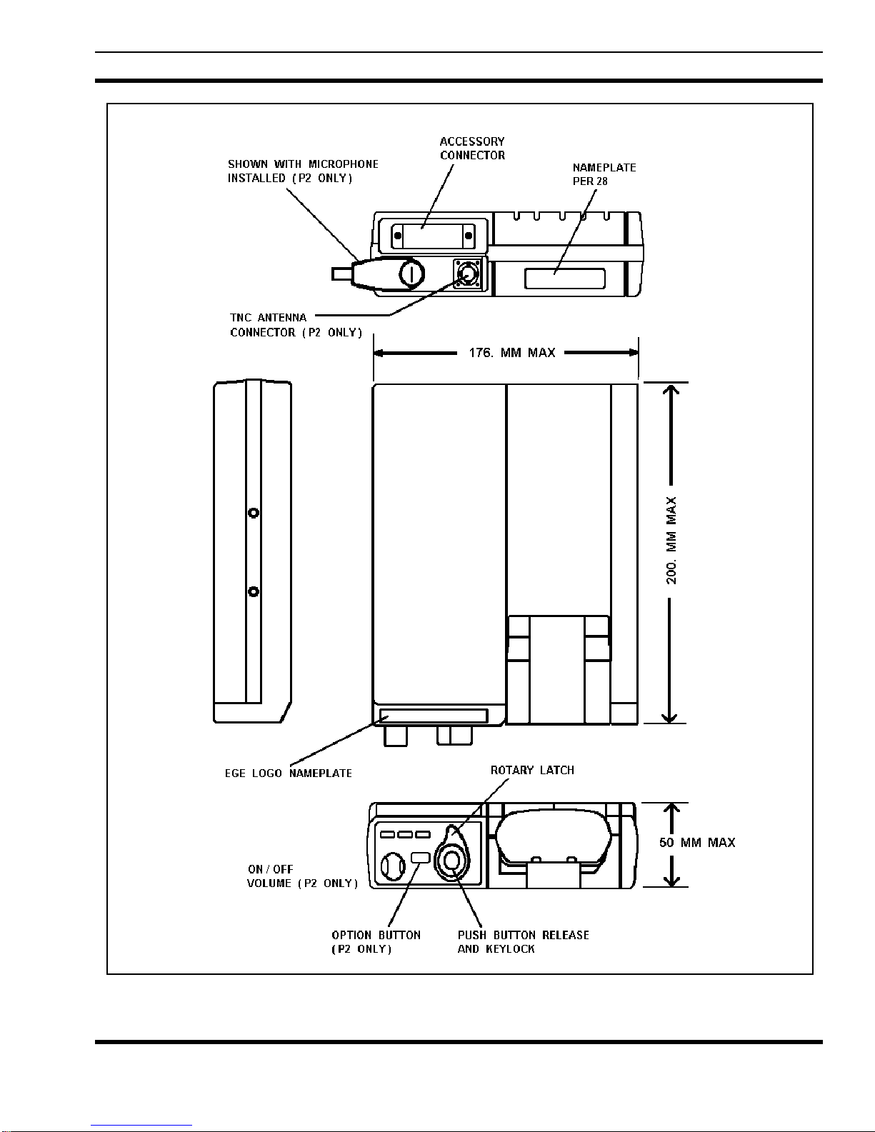
Size (H x W x D) 200 x 176 x 50 mm (7.8 x 6.9 x 1.9 inches)
Weight 1.2 Kg (2.6 lbs. [avoir.])
Indicator Lights
Charging (high rate) Yellow LED
Ready Green LED
Transmit Red LED (P2 only)
Repeater EnabledRed LED (P1 only)
*
Radio Latch Rotary knob with push-button release (lockable)
Maximum Recharge Times
1200 mAh Battery Pack 60 minutes
1700 mAh Battery Pack 60 minutes
Temperature Limits
Charging +5 to +45°C
Operating -30 to +60°C
Charge Fault Detection shorted cell and charge temperature limits
Duty Cycle 100% receive, 10% transmit
ELECTRICAL
Nominal Input Voltage 13.8 Vdc (negative ground)
Input Voltage Limits 10.8 to 16.6 Vdc
4
Continued

Continued
LBI-38936
SPECIFICATIONS
Maximum Current Drains
Off 5 mA
On And Not Charging 100 mA
Charging And Radio
Squelched 2.0 Amperes
Charging And Ext. Spkr.
At Rated Output 3.5 Amperes
Battery Charge Currents
Fast Charge 1200 mA ±150 mA
Slow Charge 100 mA ±20 mA
External Speaker Amplifier 10 Watts
Rated Audio Power Output
External Speaker Amplifier 5% at 10 Watts
Maximum Audio Distortion
External Speaker Amplifier ±1 dB from 300 to 3000 Hz
Frequency Response
Antenna Port Impedance 50 ohms
Maximum Antenna Port Loss 1.0 dB from UDC to TNC connector
*
ENVIRONMENTAL TESTS
STANDARD METHOD PROCEDURE TEST
MIL STD 810-C/D 514.2 VIII CAT F Vibration
MIL STD 810-C/D 516.2 I & II Shock
MIL STD 810-C/D 502.1 I Low Temperature
MIL STD 810-C/D 501.1 I High Temperature
MIL STD 810-C/D 501.2 II Operational Temperature
MIL STD 810-C/D 503.1 I Temperature Shock
MIL STD 810-C/D 503.2 I Temperature Shock
MIL STD 810-C/D 507.1 II Humidity
MIL STD 810-C/D 500.1 II Low Pressure
EIA RS-316-B Temperature
EIA RS-316-B Supply Voltage
EIA RS-316-B Vibration
EIA RS-316-B Humidity
514.2 X Vibration
514.3 I CAT 1 & 10 Vibration
516.3 I Shock
502.2 II Low Temperature
501.2 II High Temperature
507.2 II Humidity
500.2 II Low Pressure
∗ These specifications are intended primarily for use by service personnel. Refer to the appropriate
Specification Sheet for complete specifications.
5

LBI-38936
DESCRIPTION
Ericsson GE Vehicular Charger/Repeater units
344A4616P1 (Part 1) and 344A4616P2 (Part 2) provide a
mobile charging capability for either the M-RK I or MRK II personal hand held radios. These charger/repeater
units operate with either the standard high capacity
(19A149838P1 - 1200 mAh), or the extra high capacity
(344A3278P1 - 1700 mAh) nickel-cadmium battery
packs. The personal radio battery pack has a charging
current applied whenever the radio is inserted into the
charging sleeve. An enable/disable function is included
for the Part 1 (Vehicular Repeater System) charger.
With the Part 1 charger, the Vehicular Repeater
System is active only when the M-RK radio is
charging sleeve. When the M-RK is out of the charging
sleeve only then can the M-RK transmitted signal be
routed through the repeater. Inserting the radio into the
charging sleeve switches off the repeater.
With the radio out of the charging sleeve, the repeater
enable switch must also be in the enable position for
repeater operation. This switch is part of the repeater
receiver. When it is in the on position the
labeled
When a radio is inserted into the charger, charging
contacts are automatically made at the back of the radio.
A radio detect microswitch (S1), located near the charging
contacts, applies power and the fast charge begins,
provided the battery is in the acceptable temperature
range. A second microswitch determines the charging rate
required based upon battery size.
The High/Low temperature limit detector circuit
measures battery pack temperature by monitoring the
resistance of the battery thermistor. It provides a signal to
the charge microprocessor if the battery is within
acceptable temperature limits for fast charging.
The radio can be operated while in a Part 2 charger.
Provision for this operation is designed into the charger
with a vehicular antenna and a remote microphone
connected at the bottom of the charger (Refer to Figure
1B). The connections to the radio required for this
operation are made through the Universal Devices
onnector
C
charger by turning the front panel rotary latch knob
clockwise to the locking position. In this position the
UDC contacts meet with mating contacts on the M-RK I
or II personal radio for operation and the radio is locked
into the charger. Pushing a release button on the top of the
rotary latch knob releases and disconnects the radio from
operation. This release button arrangement is supplied
with a key that can be used to lock the push-button in the
clockwise (locked) position. With the lock engaged, the
RPT
lights.
when the radio is inserted in the
(UDC)
not
RED
in the
LED
release cannot be pressed. This locks the radio to the
charger and it cannot be removed.
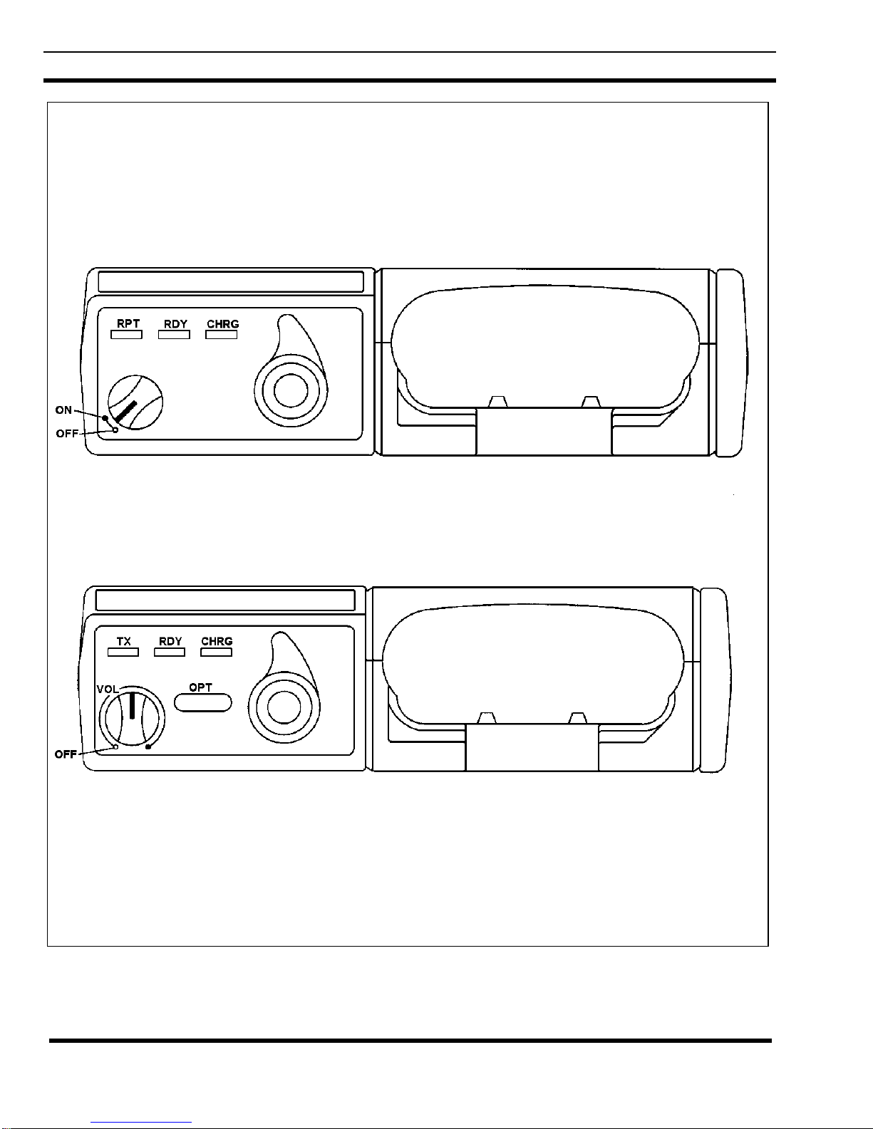
STANDARD VEHICULAR CHARGER
(344A4616P1)
The front panel of this charger contains three (3)
indicator lights;
switch for the Repeater Radio and the
LATCH KNOB
(1) Indicator Lights:
RPT
powered ON.
RDY
percent charged and the charger reverts to "trickle"
charge.
CHRG
inserted in the charger. Indicates Radio is being
"fast" charged.
(2) Repeater ON/OFF switch:
Turning this switch ON any time the M-RK
personal radio is out of the charger powers the
repeater radio and lights the Red Indicator light.
(3) UDC Rotary Latch Knob:
This knob latches the M-RK personal radio in the
charger and only secures the radio into the charger.
When the latch is activated, no other electrical
connections are made to the radio. It should always
be latched when the radio is in the charger and the
vehicle is moving.
RPT, RDY
(Refer to Figure 1A and 1B).
(Red) - Lights if the Repeater Radio is
(Green) - Lights if the Battery is 90 to 100
(Yellow) - Lights when radio is first
, and
, an
CHRG
UDC ROTARY
ON/OFF
ENHANCED VEHICULAR CHARGER
(344A4616P2)
The front panel of this charger contains three (3)
indicator lights;
volume control switch for operation of the M-RK personal
radio as a mobile radio, an option push-button, and the
UDC ROTARY LATCH KNOB
(1)
Indicator Lights
(Red) - Lights if the M-RK transmitter is
TX
active.
RDY
percent charged and the charger reverts to "trickle"
charge.
CHRG
in the charger. Indicates Radio is being "fast"
charged.
(2)
ON/OFF
TX, RDY
(Green) - Lights if the Battery is 90 to 100
(Yellow) Lights when radio is first inserted
Volume Control Switch:
:
, and
CHRG
(Refer to Figure 1A).
, an
ON/OFF
6

LBI-38936
This switch powers the radio for operation as a
mobile. Check to assure that the UDC LATCH
KNOB is in the "engaged" position.
(3) Option Push-Button:
This button can be programmed for many
functions, but factory programming causes the
same action as the M-RK "Clear" function. (See the
M-RK Operator's Manual LBI-38732 (or LBI-
38733).
(4) UDC Rotary Latch Knob:
This knob latches the M-RK personal radio in the
charger and connects the UDC to all circuits within
the charger to allow M-RK radio operation as a
mobile radio. It should always be latched when the
radio is in the charger and the vehicle is moving.
ELECTRICAL DESCRIPTION
The M-RK Vehicular Charger provides the following
electrical functions (see to Figure 2):
• Accessory connector
• Alternator noise/transient filter
Alternator Noise/Transient Filter
This filter reduces the alternator noise on the
incoming DC power to prevent noise form being heard
from the receiver or appearing on the transmitted signal.
The transient filter prevents damage due to reverse
polarity dc voltages, or from high voltage, positive or
negative voltage spikes, caused by automotive electronics.
High Rate Constant Current Source
This is an active constant current source used to
regulate charge current. It has adequate heatsinking to
dissipate the heat created with 16.5 Vdc input and a
battery pack with one shorted cell.
Charge Control
The charge control enables or disables the high rate
constant charge current. This circuit is connected in the
constant current source and is controlled by the charge
control microcontroller (IC4)
Power Supply
• High rate constant current source
• Charge control
• Power Supply
• Charge control microcontroller
• Hi/Low temperature limit detector
• Audio Amplifier
• 5-Volt regulator
• Remote control logic interface
• Microphone connector
• Antenna connector
• Universal Devices Connector (UDC)
• Bypassing
• Shielding
Accessory Connector
A DB15 Accessory Connector (CN1) provides
connections for the power cable, speaker leads emergency
foot switch, hookswitch and optional control unit leads to
the charger. DC power from the vehicle battery is routed
through the on/off power switch in the radio insert and
then to the alternator noise filter.
This is a current limited, constant voltage power
supply which is enabled when the radio is in the transmit
condition. This power supply will power the radio when
the battery is completely discharged by forcing a
minimum voltage of 7.5 V to appear across the battery
pack. The current limiting prevents damage to the
regulator when a battery pack with one or more shorted
cells is in the charging insert. This power supply is
enabled by the T/R output lead at the radio UDC. The red
PTT indicator lights when the power supply is enabled.
The power supply is designed to prevent the trickle charge
from flowing into the power supply when the power
supply is turned off and in the receive mode.
Charge Control Microprocessor
Functions performed by this controller are:
1. Shorted cell detection
2. Battery removal sensor
3. Battery charger latch
4. Minus delta V sensor for charge control
5. Charge indicator control and fault display
7
LBI-38936
STANDARD/REPEATER CONTROL M-RK VEHICULAR CHARGER 344A4616P1
ENHANCED M-RK VEHICULAR CHARGER 344A4616P2
Figure 1A - M-RK Vehicular Chargers
8
LBI-38936
Figure 1B - M-RK Vehicular Charger
9
 Loading...