

Page 1
LBI-3868 6A
Operator’s Manual
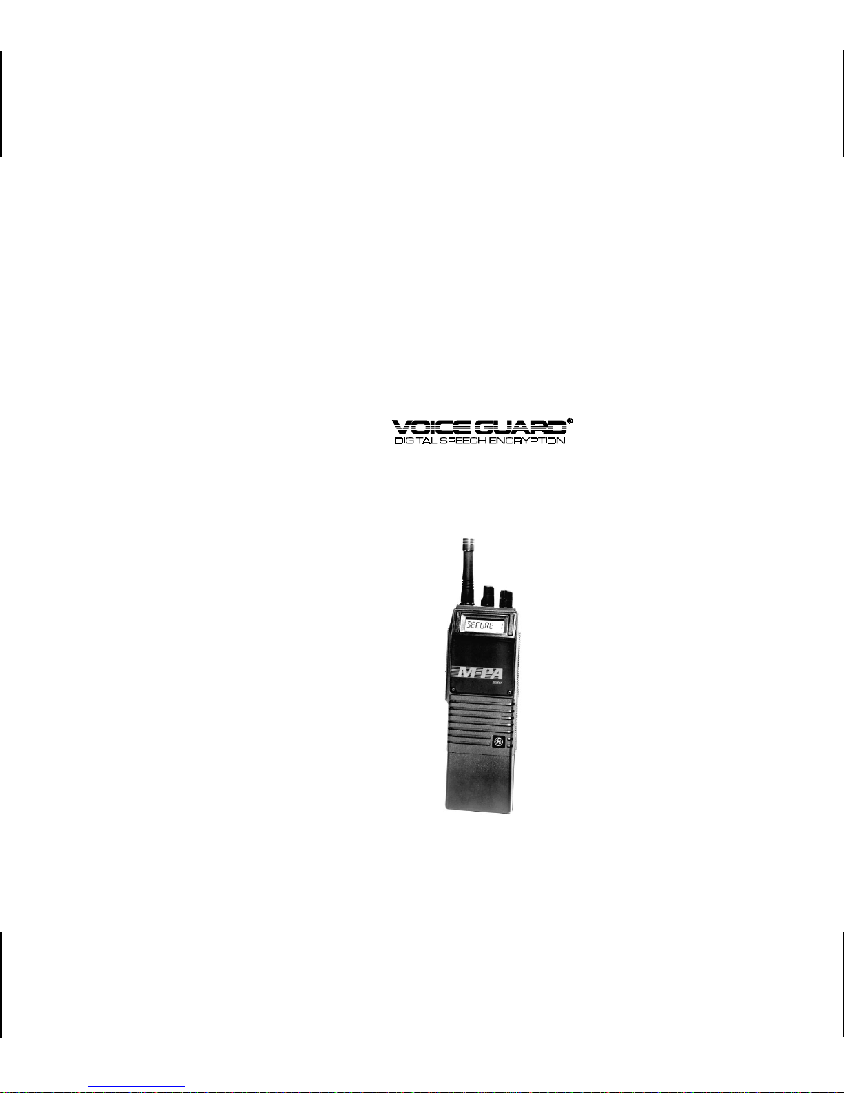
M-PATM SELECT MODEL
PORTABLE RADIO
(DES ALGORITHM)
E
Page 2

TABLE OF CONTENTS
TABLE OF CONTENTS (CONT.)
INTRODUCTION . . . . . . . . . . . . . . . 5
CONTROLS . . . . . . . . . . . . . . . . . 5
INDICATORS . . . . . . . . . . . . . . . . . 7
UNIVERSAL DEVICE CONNECTOR . . . . 8
ALERT TONES . . . . . . . . . . . . . . . . 8
OPERATION . . . . . . . . . . . . . . . . . 9
POWER-UP . . . . . . . . . . . . . . . . 9
CRYPTOGRAPHIC KEY HANDLING . . . 9
RECEIVING A MESSAGE . . . . . . . 10
TRANSMITTING A MESSAGE . . . . . 11
EMERGENCY OPERATION . . . . . . 12
OPERATING TIPS . . . . . . . . . . . . . 12
OPERAT ING RULES AND
REGULATIONS . . . . . . . . . . . . . . 13
BATTERY PACKS . . . . . . . . . . . . . 14
INSTALLING THE BATTERY PACK . . . 14
REMOVING THE BATTERY PACK . . . 15
CHARGING THE BATTERY PACKS . . 15
RECHARGEABLE BATTERY PACK
DISPOSAL . . . . . . . . . . . . . . . 16
SWIVEL MOUNT REMOVAL AND
REPLACEMENT . . . . . . . . . . . . . . 16
INTRINSICALLY SAFE USAGE . . . . . . 16
BATTERY PACKS . . . . . . . . . . . . 17
ACCESSORIES . . . . . . . . . . . . 17
GLOSSARY . . . . . . . . . . . . . . . . 18
WARRANTY . . . . . . . . . . . . . . . . 20
NICKEL-CADMIUM WARRANTY . . . . . 21
This manual is published b y
or improvements to programs and/or equipment, may be made by
part of this manual may be reproduced or transmitted in any form or by any means, electronic or mechanical, including photocopying and recording, for any purpose, without the express
written perm i ss i on of
Copyright © December 1991, Ericsson GE Mobile Communications Inc.
Ericsson Inc.
Ericsson Inc., w
ithout any warranty. Improvements and changes to this manual necessitated by typographical errors, inaccuracies of current information,
Ericsson Inc.,
at any time and without notice. Such changes will be incorportated into new editions of t his manual. No
2
Page 3

PRODUCT SPECIFICATION FOR CE MARKED
EQUIPMENT
The M-P A P ortable conforms to the following Prod-
uct Specifications.
EUROPEAN STANDARDS:
Safety: Not Applicable
EMC: prETS 300 279 (August 1995)
TTD: Not Applicable
SUPPLEMENTARY INFORMATION:
At this time, the M-PA portable radio may not be
operated whi le in a v e hicu lar char ger i n the Euro pean
Communi ty sin ce i t has no t been e valuated for oper ation in this mode.
The M-PA portable radio may be used in both
trunked an d co nventio na l ap pl ic at io ns.
3
Page 4
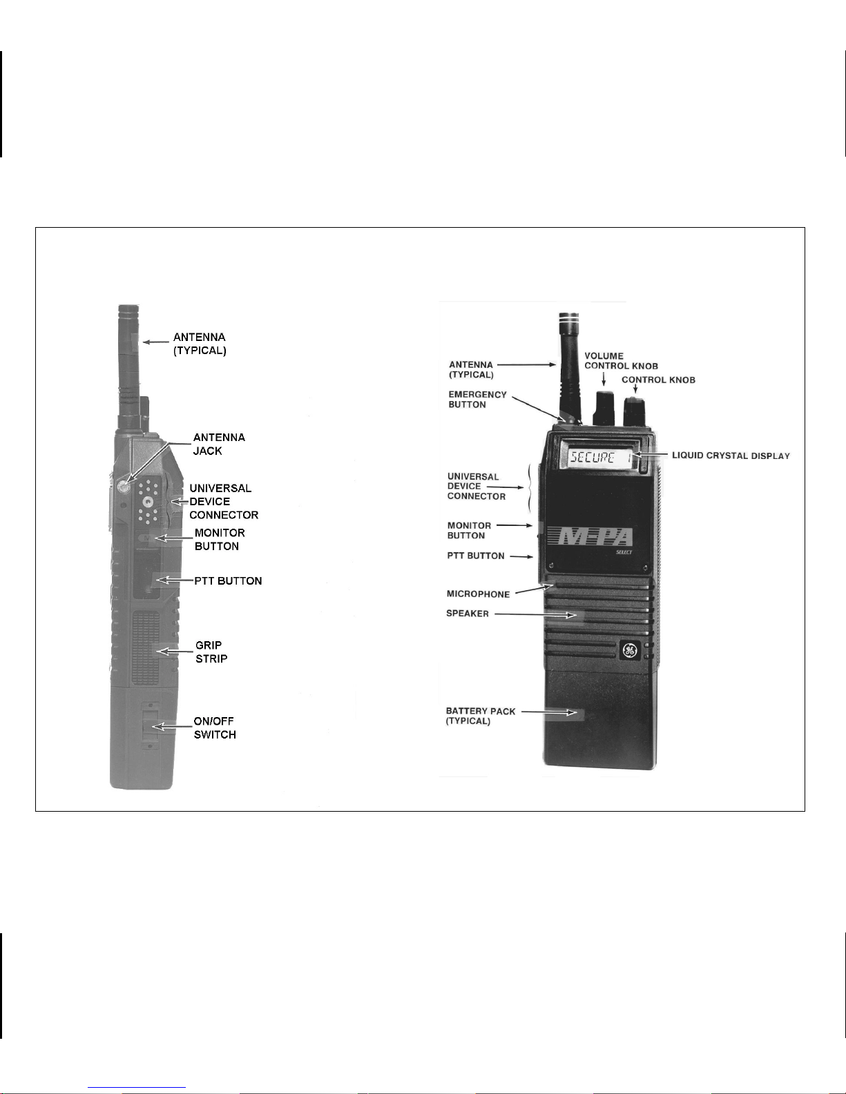
SIDE VIEW
FRONT VIEW
4
Figure 1 - M-PA Select Model Radio
Page 5

INTRODUCTION
This manual de scrib es the ope ration of the
M-PA
Vo i c e G u a r d® Select mo del radio. This f ullfeatured portable radio provides V oice Guard two-way
communi cati ons us ing th e Data Encryption Sta ndard
(DES) algorithm. The M-PA Voice Guard radio provides full-range performance for private (guarded) and
clear communications.
The cr yptographic key in the radio provides the
encryption and decryption code necess ary f or pri va te
communicatio ns. Only ra dios with the sa me cryp tographic key can monitor and communicate. Cryptographic keys are transferred into the radio using DES
Keyloader , Option V4025.
Operatin g controls on the radio include a rotatable
control knob, rotata ble volume con trol, push-to-talk,
emergency and monitor buttons. The on/off power
switch for the unit is located on the removable battery
pack.
such as private comm un ic at io ns en abled, tra ns m it te r
on, or emer ge nc y m od e enabled.
The exact operation of your radio will vary depending upon the mode of operation, the radio’s programming, and the particular radio system. Consult
your radio system’s representative for par ticular features that are programmed into your radio.
CONTROLS
ON/OFF SWITCH
The ON/OFF SWITCH is loc ated on the batt ery
pack. Sliding this switch up will supply power to the
radio from the battery pack. An audible click will be
heard and the "ON" indic a tor will be exposed. When
the radio is turned on, it will perform a power-up self
test and then resum e oper ation o n the pr e vious operating channel as displayed in the LCD. Sliding the
swi tc h down will turn the ra di o off.
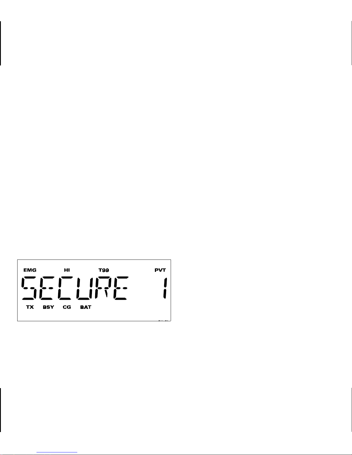
The 8-digit alphanumeric liquid crystal display
(LCD) on th e front of the radio displays the operating
status of th e r a di o. T hi s backlit d is play al so h as e ig ht
status fl ags t hat indi cate v ari ous oper at ing cond itio ns
VOLUME CONTROL KNOB
The VOLUME CONTROL KNOB is a rotatable
control on the top of the radio used to adjust the
receiver’s audio level in the speaker. Rotating this
5
Page 6

knob in a clockwise direction will increase the audio
level. Counter-clockwise rotation will decrease the
audio le v el. Min imum le v els ma y be prog ramme d into
the radio to prevent missed calls due to too low of a
volum e se tt in g.
CONTROL KNOB
The rotatable 16-position CONTROL KNOB located on the top of the radio selects the operating
channel. A stop plat e may be insta lled under the knob
to limit the maximum number of positions to less than
sixteen (16). It is normally factory installed for fifteen
(15) positions.
squelch an d the receiver noise will be heard in the
speaker.
If programmed e nabled for the selected channel,
Channel Guard (CG) and/or Type 99 (T99) signalling
will be enabled when the channel is selected. If CG
and/or T99 are en abled, th e appropriate stat us flag
"CG" and/or "T99" will turn on. The MONITOR BUTTON may then be used to toggle CG and/or T99
between disabled and enabled by pressing and holding the it for at least one (1) second; the appropriate
status flag will toggle on or off. The MONITOR BUTTO N is als o use d to re set T 99 oper at ion afte r a cal l is
received.
PTT BUTTON
Pressing the PTT BUTTON on the side of the
radio will enable the radio’s transmitter. The "TX"
status fl ag in the d ispl a y w il l turn on when th e r adi o is
transmit ti ng . Releasing t he P TT BUT TON will retu rn
operation to receive mode.
MONITOR BUTTON
The MONITOR BUTT ON is used to unsquelch the
receiver. Momentarily pressing this button will disable
6
EMERGENCY BUTTON
The EMERGENCY BUTTON is the small red
button lo cated on top of the radi o near the ante nna. If
this button is programmed for emergency operation,
pressing it for at least one (1) second will cause the
radio to t ransmit GE- STAR emergency sign alling. The
"EMG" status flag will turn on. GE-STAR is tr ansmitted
according to one of several different programmable
methods. See EMERGENCY OPERATION for de-
tails.
Page 7
This button may also be programmed as a home
mode button. If programmed in this manner, pressing
it will switch operation to the programmed home
mode.
INDICATORS
The eight (8 ) status flags locat ed along the top
and bottom of the display indicate operating status as
follows:
EMG EMerGency mode - On indicates emer-
gency GE-STAR signalling has been initiated by the user.
The radio’s liquid crystal dis pla y (LCD) located on
the front panel has eight (8) alphanumeric characters
and eigh t (8) stat us flags. This display indicate s the
current op erating channel an d various messa ge s .
LCD backlighting will turn on for a short period
anytime an acti v e bu tton i s pre ssed o r the CON TR OL
KNOB is rotated. Backlighting may be programmed
to remain off at all times.
Figure 2 - Liquid Crystal Display
HI HIgh power transmit - On indicates the
selected channel has been programmed
for high power transmit operation. Off
indicates low power transmit.
T99 Type 99 tone decode - On indicates Type
99 tone decoding is enabled on the selected channel. Flashing indicates a T99
selective call has been received and the
radio must be reset to receive another
T99 call.
PVT PriVaTe mode - On indicates private
mode is enabled and the radio will transmit encrypted messages on the selected
channel. Flashing indicates an encrypted
message is being received.
TX Transmitter enabled - On when the radio
is transmitting.
BSY BuSY - On indicates a carrier is being
received (the channel is busy). Note that
if the selected channel is programmed for
7
Page 8

Channel Guard (CG), Digital Channel
Guard (DCG), or Type 99 (T99) tone decode operation, the radio may not unsquelch if a valid tone(s) is not received;
the BSY status flag will be on.
CG Channel Guard - On indicates tone Chan-
nel Guard (CG) or Digital Channel Guard
(DCG) encode/decode is enabled on the
selected channel.
BAT BATtery low - On indicates the battery
pack’s charge is low.
UNIVERSAL DEVICE CONNECTOR
The Universal Device Connector (UDC) is located
on the side of the radio just above the PTT and
MONITOR BUTTONS. This connector provides connections for the exte rnal access ories such as a h eadset, a speaker-mike, or an emergency lanyard. When
the radio is locked in a vehicular charger/repeater the
UDC provides the audio and control connections between the radio and the vehicular cha rger/repeater.
The UDC is also used by the maintenance personnel
when the radio is programmed.
ALERT TONES
The M-PA uses alert tones or "beeps" to indicate
various operating conditions. The alert tones may be
disabled when the radio is programmed.
CARRIER CONTROL TIMER
This feature, programmable on a per channel
basis, prevents unnecessary channel traffic and radio
damage in the event of a "stuck" mic. If the programmed timer times-ou t during a transmission the
radio will so und an al er t tone and disable the trans mission . The beepin g tone w ill con tinue unti l the PT T
BUTTON is released. Releasing the PTT BUTTON
resets the ti m er.
CHANNEL BUSY
If the radio is receiving a signal when the PTT
BUTTON is pressed, an aler t tone will warn the operator that the radio is receiving a carrier and the
transmission will not occur. "RX BUSY" is displayed
and the alarm is sounded as long as the PTT BUTTON
is presse d. This f e atur e i s pr og ram mab l e on or off on
a per channel basis.
8
Page 9

RECEIVE ONLY CHANNEL
CRYPTOGRAPHIC KEY HANDLING
If the selected channel is programmed as receive
only the radio will sound an alert tone if a transmission
is attempted. "RX ONLY" is displayed.
RADIO/CHANNEL FAILURE
If the synthesizer is unable to lock correctly on the
selected channel, or another radio failure occurs, an
alert tone will sound. If incorrect programming is
detecte d or the synthesizer fails to lock, the displ ay
flashes "NO LOCK" then the selected channel’s
name.
OPERATION
POWER-UP
After the battery pack and antenna have been
installed, turn the radio on by sliding the ON/OFF
SWITCH on the battery pack up. After the radio has
completed a pow er-u p self- test, it will begin o pera tion
on the last oper at ing s tate as di sp la y e d in t he LC D. If
programmed on, th e power-up aler t tone (beep) will
be heard.
Crypt ograp hi c keys are transferred int o th e radi o
using the Keyloader, Option V4025. Refer to the
Keyloader operator’s manual (LBI-31541) for detailed
instructions on how to load keys into the Keyloader.
The radio is capable of storing up to seven (7)
different cr yptograp hic keys in its memor y. It is programmed for key selection on a per channel basis.
NOTE
Before private messages can be sent or
received, one or more cryptographic keys
must be transferred into the radio from the
Keyloader.
Transferring Keys Into The Radio
The following procedure outlines basic key transferring steps. See LBI-31541 for more details.
1. Turn the radio off.
2. Plug the modular connector of the Key-
loader cable into the Keyloader’s modular
jack.
9
Page 10

3. Connect the Ke yloader cable to the UDC on
the radio.
4. Press the PWR button on the Ke yloader and
wait for the Keyloader to display "MASTER
MODE".
5. Press the TRN button on the Keyloader. If
necessary, select a different cryptographic
key to be transferred into the radio.
6. Turn the radio on. The display should read
"KEY LOAD".
7. Press the EXE button on the Keyloader to
transfer the key. The Keyloader will display
"GOOD 1.x TRANSFER" where "x" is the
selected cryptographic key number.
8. Disconnect the cable from the radio’s UDC.
A single beep will be heard from the radio’s
speaker if the power-up alert tone is enabled. The radio will change to the selected
channel as indicated in the display.
Key Zero
All cryptographic keys stored in the radio can be
zeroed or "dumped" by removing the battery pack for
several minutes (typica lly thre e). When the battery
pack is late r reinst alle d and th e radio is powered-up,
it will displa y "KEY ZERO" and emit a series of beeps.
If cry pt ograp hi c key(s) are zero ed, o ne or mo re keys
must be transfe r red in to th e radio from th e Keyloader
before private communications may continue. Disassembling the front half of the radio from the rear half
will also zero all keys.
RECEIVING A MESSAGE
1. Slide the ON/OFF SWITCH on the battery
pack to the on position. The radio will initiate
and complete the power-up self-test and
beep if the power-up alert tone is programmed on.
2. Select the desired channel.
3. Press the MONITOR BUTTON to disable
squelch and adjust the VOLUME CONTROL for the approximate desired speaker
audio level. Pressing the MONITOR BUTTON ma y affect Channel Guard and/or Type
10
Page 11

99 tone operation if programmed for the
selected channel.
4. If the selected channel is programmed for
private operation, the radio will automatically switch between clear or private receive operation.
When an encrypted transmission is received, the "PVT" status flag will flash, the
receiver will unsquelch, and the Voice
Guard message will be heard in the speaker .
The selected channel must be programmed
for priv ate operation and the cor rect cryptographic key must be loaded into the radio
for this to occur.
If a clear mode (non-encrypted) transmission is received, the receiv er will unsquelch
and it will be heard in the speak er. Howe ver ,
if the selected channel is programmed for
Channel Guard or Type 99 tone operation,
the receiver will not unsquelch unless the
correct CG or T99 tone is received.
5. Adjust the volume as necessary.
TRANSMITTING A MESSAGE
1. Select the desired channel. If a channel
programmed for private operation is selected and there is no key in the r adio for the
selected channel "NO KEY x" (where "x" is
the key number) will periodically flash in the
display. If a transmission is attempted, "NO
KEY x" will show in the display and the r adio
will emit a series of beeps and will not
transmit.
2. Ensure no one is transmitting on the selected channel by pressing the MONITOR
BUTTON to disable squelch or observing
the display for the absence of the "BSY"
status flag. If the Channel Busy Lockout
feature is programmed for the selected
channel, the radio will not transmit when the
channel is busy.
3. Press and hold the PTT BUTT ON. The "TX"
and "BSY" status flags are displayed.
4. Hold the radio approximately three inches
from your mouth and speak into the microphone in a normal voice.
11
Page 12

5. Release the PTT BUTT ON when the tr ans-
mission is complete. If the transmission
exceeds the programmed Carrier Control
Timer limit, the radio will unkey and an alert
tone will sound.
6. Listen for a reply.
EMERGENCY OPERATION
• GE-STAR is transmitted on the selected
channel. If the channel is changed the emergency bursts will follow the newly selected
channel.
• The radio switches to and stays on a predetermined channel and GE-STAR is transmitted on that channel. Rotating the CONTROL
KNOB will not change channels. Turning the
radio off and back on will reset this condition.
The radio may be pr ogrammed to transmit GESTAR emergency signalling when the EMERGENCY
BUTTON is pressed or fro m a UDC connected l anyard. If the EMERGENCY BUTTON is programmed
for GE-STAR emergency activation, press it for approximately on e (1) se cond to activate th e transmis sion. If the lanyard is programmed for activation,
follow the ins tructions provided wit h it. GE-STAR is
programmed to transmit in one of the following methods:
• GE-STAR is transmitted on a pr edetermined
channel regardless of the selected channel.
In this case the selected channel is available
for voice and the radio will periodically "jump"
to the predetermined channel and send the
emergency message and then "jump back"
to the selected channel for voice operation.
• GE-STAR is sent on the selected channel
and the radio locks onto that channel. Rotating the CONTROL KNOB will not change
channels. Turning the radio off and then
back on will reset this condition.
OPERATING TIPS
Antenna location and condition is important when
operatin g a po rtable r ad io. Operati ng th e r adio in l ow
areas of terrain, under power lines or bridges, inside
of a vehicle or in a metal or steel framed building can
severely reduce the range of the unit. Mountains and
buildings can also reduce the range of the unit.
In areas where transmission or reception is poor,
some improv ement ma y be obtained by insuring that
the antenna is vertical. Mo ving a few y ards in another
direction or moving to a higher elevation may also
12
Page 13

improve comm unication. Vehicular operation can be
aided with the use of an externally mounted antenna.
Battery condition is another important factor in
the trouble free operation of a portable radio . Always
properly charge the batteries.
Always obser ve all of the Federal Communication Commission’s rules and regulations.
OPERATING RULES AND REGULATIONS
serve the display for the absence of the
"BSY" status flag before transmitting.
Emergency calls have priority over all other
messages. If someone is sending an emergency message - such as reporting a fire or
asking for help in an accident - KEEP OFF
THE AIR!
2. The use of profane or obscene language is
prohibited by Federal law.
Two-way FM radio systems must be operated in
accordance with the rules and regulations of the
Federal Com munications Commission (FCC). As an
operator of two-way radio equipment, you must be
thoroughly familiar with the rules that apply to your
particular type of radio operation. Following these
rules will help eliminate confusion, assure the most
efficient use of the existing radio channels, and r esult
in a smoothly functioning radio network.
When using your two-wa y radio, rem ember these
rules :
1. It is a violation of FCC rules to interrupt any
distress or emergency message. As your
radio operates in much the same way as a
telephone "party line", always listen to mak e
sure that the channel is clear and/or ob-
3. It is against the law to send false call letters ,
or false distress or emergency messages.
4. The FCC requires that you keep conversations brief and confine them to business. To
save time, use coded messages whenever
possi bl e.
5. Using your radio to send personal messages (except in an emergency) is a violation of FCC rules. You may send only those
messages that are essential for the operation of your business.
13
Page 14

6. It is against Federal law to repeat or otherwise make known anything you o verhear on
your radio. Conversations between others
sharing your channel must be regarded as
confidential.
7. The FCC requires that you identify yourself
at certain specific times by means of your
call letters. Refer to the rules that apply to
your particular type of operation for the
proper procedure.
8. No changes or adjustments shall be made
to the equipment except by an authorized or
certified electronic technician.
BATTERY PACKS
3. Align the battery pack and radio slide
grooves. See Figure 3.
4. Slide the battery pack fully into the radio
until the battery release latch clicks into
place.
INSTALLING THE BATTERY PACK
1. Ensure the ON/OFF SWITCH on battery
pack is in the off position.
2. Hold the radio and battery pack with the
back of them facing you.
14
Figure 3 - Installing the Battery Pack
Page 15

REMOVING THE BATTERY PACK
1. Ensure the ON/OFF SWITCH on the battery
pack is in the off position.
2. Press down on the battery release latch and
slide the battery pack out in the direction of
the release latch. See Figure 4.
Figure 4 - Removing the Battery Pack
CHARGING THE BATTERY PACKS
After receiving a new rechargeable battery pack
from the factory, it should be fully charged before
placing it into service. T his also applies to r echargeable batteries that have been stored f or long periods.
When the battery pack requires charging the radio
will signal the operator with an alert tone and the
"BAT" status flag will turn on.
Chargers are available with nominal charge
times of 1 hour (rapid) and 14 hours (standard).
Combinations include single (1) and multi (5) position, standard and rapid charge units. In addition, the
vehicular chargers/repeaters simultaneously charge
the battery packs while the radio is operating. For
specific instructions refer to the applicable charger
Operating Manual.
The rechargeable batteries used with the radio
can dev elop a reduced capacity condition sometimes
called the "Memory Effect". T his condition can occur
when a battery is continuously charged for long
periods or when a regularly performed duty cycle
allows the battery to expend only a limited portion of
its capacity. The battery pack may show a severe
decrease in its ability to deliver full capacity for an
extended period. Any rechargeable battery pack
showing signs of reduced capacity should be returned to a qualified service center for inspection.
15
Page 16

RECHARGEABLE BATTERY PACK DISPOSAL
The product that you have purchased co ntains a re chargeable, recyclable battery. At the end of it’s useful
life, under variou s stat e a nd lo ca l l aws,
it may be illegal to dispose of this battery
into the municipal waste stream. Check with your local
solid wa ste officials f or details in you r area for r ecycling
options or proper disp osal. Call Toll F ree 1-80 0-8-BATTERY fo r information and/or procedur es for re turning
rechargeable batteries in your state.
SWIVEL MOUNT REMOVAL AND
REPLACEMENT
To remove the swivel mount, slide a flat blade
screwd river underneath the spring reta in er a nd tw ist.
While twisting, slide the swivel mount out from under
the holder.
To replace the swiv el mount, place the end of the
swi vel in the g r ooves in th e r a dio and slid e th e m ount
up until it snaps in place.
16
Figure 5 - Swivel Mount Removal and Replacement
INTRINSICALLY SAFE USAGE
Selected portable radios with appropriate factory
installed F4 Options are certified as Intrinsically Safe
by the Factory Mutual Rese arc h Co rporatio n. Intrinsically Safe approval includes Class l, II, Ill, Division 1
hazardous locations in the presence of Groups C, D,
E, F and G atmospheres. Non-Incendive approval
includes Cl ass I, Divisi on 2 hazardous lo cations in t he
presence of Groups A, B, C and D atmospheres.
Hazardous locations are defined in the National Electrical Code. Useful standards NFPA 437A and NFPA
Page 17

437M for the classifications of hazardous areas can
be ordered from the National Fire Protection Association, Batterymarch Park, Quincy, MA 02269.
PAAE3R Speaker/Microphone
PAAE1B Speaker/Microphone with GE-
STAR Lanyard
BATTERY PACKS
Only batt ery packs id entified with a green latch
shall be us ed with a por table radi o that is rated an d
labeled as Factory Mutual Intrinsically Safe. Use of
nonspecified battery packs voids Factory Mutual approval. The following battery pack options are approv e d for use in intrinsicall y sa fe radios.
PA PA1F Rechargeable Battery Pack,
Extra High Capacity (Tall Case)
PA PA1G Rechargeable Battery Pack,
High Capacity (Short Case)
ACCESSORIES
The accessories that follow are approved for use
with intri nsical ly saf e r adio s. Use of access ories other
than those listed voids Factory Mutual approval.
PAAE3T Speaker/Microphone/Antenna
PA NC1B Antenna, 136-151 MHz, Helical
PA NC1F Antenna, 440-470MHz, Helical
PANC1L Antenna,378-440MHz, Whip
PANC1N Antenna,440-512MHz, Whip
PANC1H Antenna, 806 - 870 MHz, Ele-
vated Feed
PA NC1K Antenna, 806-870MHz, Flex
PA NC1U Antenna, 378-440MHz, Helical
PANC1Z Antenna,896-941MHz, Whip
PAHC1C Belt Clip
PA HC1D Swivel Mount with Belt Loop
PA HC3W Case, Leather, with Belt Loop
(Short Case)
PAPAB1A Headset/Microphone
PA AC1J Earpiece Kit
PAAC1B GE-STAR Lanyard
PA HC1K Shoulder Strap, Leather, with
Mounting Plate
PAHC5R Holster, Plastic.
17
Page 18

GLOSSARY
clear mode - communicating in a non-en-
crypted format (non-scrambled)
cryptographic key - the number or code used by the
encryption and decryption circuitry to encode and decode a
signal
DES - Data Encryption Standard - a
Federally accepted encryption/decryption algorithm used
to scramble or descramb le a signal
decryption - the process of decoding or de-
scrambling a signal according to
a predetermined algorithm
CCT - Carrier Controlled Timer - a pro-
grammable timer that will disab le
a transmission if the timer length
is exceeded
CG - Channel Guard - a method of
controlling squelch with a tone or
digital code (Channel Guard is
tradename for coded squelch)
RADIO TYPE
FREQUENCY BAND
OPERATOR’S NAME
encryption - the process of encoding or
scrambling a signal according to
a predetermined algorithm
private mode - communicating in an encrypted
format (scrambled)
T99 - Type 99 - a method of opening
squelch for selective page operations using sequential tones
18
Page 19

MODE
NUMBER
MODE
NAME
CHANNEL
NUMBER
CHANNEL
NAME
VG CG/
T99
USE
19
Page 20

WARRANTY
A. Ericsson Inc. (hereinafter "Seller") warrants to the original purchaser for use (hereinafter "Buyer") that Equipment manufactured by Seller shall be free
from defects in material, workmanship and title, and shall conform to its published specifications. With respect to any Equipment not manufactured by
Seller (except for integral parts of Seller’s Equipment to which the warranties set forth above shall apply). Seller gives no warranty , and only the warranty,
if any, given by the manu facturer shal l apply. B atterie s are excluded from this war ranty but are warrante d unde r a separate Nickel-C admiu m Batter y
Warr a nty.
B. Seller’s obligations set forth in Paragraph C below shall apply only to failures to meet the above warranties (except as to title) occurring within the following
periods of time from date of sale to the Buyer and are conditioned on Buyer’s giving written notice to Seller within thirty (30) days of such occurrence:
1. for fuses, incan descent lamp s, vacuum tubes and non-rechargeable batteries, operable on arrival only.
2. for pa rts and accessories (except as noted in B.1) sold by Seller’s Service Parts Operation, ninety (90) days.
3. for all other Equipment of Seller’s manufacture, one (1) year.
C. If any Equipm ent f ails to m eet the foregoing war ran tie s, Seller sh all c orre ct t he f a ilur e at its option (i) by re pair ing an y defective or dama ged p art or parts
thereof , o r (ii) by m aking a v ailab le at Se ller’ s f acto ry any ne cess ary repa ired o r repl acem ent parts. Any repair ed or re placem ent pa rt furnished h ereund er
shall be warranted for the remainder of the warranty period of the Equipment in which it is installed. Where such failure cannot be corrected by Seller’s
reasonable efforts, the parties will negotiate an equitable adjustment in price. Labor to perform w arranty service will be provided a t no change only for
the Equipment covered under Paragraph B.3, and only during the first three (3) months following the date of sale to the Buyer. Thereafter, labor will be
charged at prevailing rates. To be eligible for no-charge labor, service must be performed by an Authorized Service Center or other Servicer approved
for these purposes either at its place of business during normal business hours, for mobile or personal equipment, or at the Buyer’s location, for fixed
location equipment. Service on fixed location equipment more than thirty (30) miles from the Service Center or other approved Servicer’s place of
business will inc lude a char ge for t ransportation.
D. Seller’s obligations u nder Paragraph C shal l not app ly to any Eq uipm ent, or pa r t ther eof, which (i) has bee n modi fied or otherw ise al tered other tha n
pursuant to S el le r’s written ins truc t io ns or wri t ten ap pr o val or , (i i) is no rma ll y c on su me d in ope r at i on or, (iii) has a normal li fe inherent l y sh orter t ha n the
warranty periods specified in Paragraph B, or (iv) is not properly stored, installed, used, maintained or repaired, or, (v) has been subjected to any other
kind of misuse or detrimental exposure, or has been involved in an accident.
E. The preced ing pa ragraphs se t fort h the exclusi ve remedies for cla ims (except as to titl e) base d upon d efects in or no nconform ity of the E quipme nt,
whether the claim is in contract, wa rranty, tor t (includi ng negli gence), str ict liabili ty or othe rwise, and h owever instituted. Upon the expiration of the
warranty period, all such liability shall terminate. The f oregoing warranties are exclusive and in lieu of all other warranties, whether oral, written, expressed,
implied or statut ory . NO I MPLIED OR S TA TUT OR Y W ARRANTIE S OF MERCH ANTABILITY OR FIT NESS FOR PARTICULAR PURPOSE SHALL A PPLY.
IN NO EVENT SHALL THE SELLER BE LIABLE FOR ANY INCIDENTAL, CONSEQUENTIAL, SPECIAL, INDIRECT OR EXEMPLARY DAMAGES.
20
This warranty applies only within the United States.
1-800-592-7711 (Outside USA, 804-592-7711).
ECX-362S
Page 21

NICKEL-CADMIUM BATTERY WARRANTY
A. Ericsson Inc. (hereinafter "Seller") warrants to the original purchaser for use (hereinafter "Buyer") that nickel-cadmium batteries supplied by Seller
shall be free from defects in ma terial and wor k manship, and shall conform to its published specifications for a period of twelve (12) months f rom
the date of purchase.
B. For purposes of this warranty, batteries shall be deemed defective if (1) the battery capacity is less than 80% of rated capacity, or (2) the battery
develops leakage.
C. If any batter y fails to me et the foregoin g war ranty, Seller shall correct the fail ure by issui ng a r epla ceme nt batte ry upon rece ipt of th e defective
battery at an Authorized Servic e Center (ASC). To obtain the name and address of an ASC, ask your salesperson, consul t the Yellow Pages, or
call the number printed at the bottom of this page.
D. Replacement batteries shall be warranted only for the remaining unexpired warranty period of the original battery. T his warr anty becomes void if:
(1) The battery has been subjected to any kind of misuse, detrimental exposure, or has been involved in an accident.
(2) The battery is used in equipment or service other than the radio equipment for which it is specified.
E. The preceding paragraphs set forth the exclusive remedies for claims (except as to title) based upon defects in or non-conformity of any battery,
whether the claim is in contract, warranty , tort (including negligence), strict liability or otherwise, and however instituted. Upon the expiration of the
warranty peri od , a ll s uc h l ia bi li ty s ha ll terminate. The foregoing warranti es ar e exclusive and in lieu of all oth er war ranties, whether oral, w r itte n,
expressed, implied or statutory. NO IMPLIED OR STATUTORY WARRANTIES OF MERCHANTABILITY OR FITNESS FOR PARTICULAR
PURPOSE SHAL L APPLY . IN NO EVENT SH ALL THE COMPANY BE LIABLE FOR ANY IN CIDENTAL, CONSEQ UENTIA L, SPE CIAL, IN DIRECT
OR EXEMPLARY DAMAGES.
This warranty applies only within the United States.
1-800-592-7711 (Outside USA, 804-592-7711).
ECX-841C
21
Page 22

22
Page 23

23
Page 24

Police
State Police
Fire
Poison Control
Ambulance
Life Saving and
Rescue Squad
EMERGENCY NUMBERS
Ericsson Inc.
Private Radio Systems
Mountain View Road
L ynchburg, V irginia 24502
1-800-592- 7 71 1 ( O ut s i d e US A , 80 4- 5 92 - 77 11) Printed in U.S.A.
 Loading...