

Page 1

Operator’s Manual
LBI-38574B
E
M-PA
EDACS
900 MHz
SELECT, SCAN, & SYSTEM
PERSONAL RADIOS
Page 2

TABLE OF CONTENTS
Page
INTRODUCTION . . . . . . . . 6
OPERATING
NOMENCLATURE . . . . . . . 6
CONVENTIONAL
OPERATION . . . . . . . . . 6
TALK-AROUND
OPERATION . . . . . . . . . 6
TRUNKED OPERATION . . . 7
SYSTEM (AREA) . . . . . . . 7
GROUP OR SUBFLEET . . . 7
FLEET . . . . . . . . . . . . 7
AGENCY . . . . . . . . . . . 7
CONTROLS, DISPLAYS AND
CONNECTORS . . . . . . . . . 8
This ma nual is published by
warranty. Improvement s and ch anges t o this ma nual necessitated by typographical errors, inaccuracies of current information, or improvements to programs and/or
equipment , may be made by
and without notice. Such changes will be incorporated
into new e ditions of this manual. No par t of this manual
may be repro duced or tran smitte d in any form or by any
means, el ectronic or mechanical, including photocopying
and record ing, for any pur pos e, wit hout the express written permission of
Copyright© April 1991, Ericsson GE Mobile Communications, Inc.
Ericsson Inc.
Ericsson Inc.
Ericsson Inc.
, without any
, at any time
CONTROLS . . . . . . . . . . 8
4 KEY CONTROL . . . . . . . 9
SECOND FUNCTION
CONTROL . . . . . . . . . . . 11
DISPLAYS . . . . . . . . . . . 13
UNIVERSAL DEVICE
CONNECTOR (UDC) . . . . . 15
OPERATION . . . . . . . . . . . 15
SELF-TEST . . . . . . . . . . 15
CARRIER CONTROL
TIMER . . . . . . . . . . . . 16
TRUNKED MODE
OPERATION . . . . . . . . . . . 16
RECEIVING A
MESSAGE . . . . . . . . . . . 16
SENDING A
MESSAGE . . . . . . . . . . . 17
EMERGENCY
OPERATION . . . . . . . . . . 17
WIDE AREA ENCODE . . . . 18
TELEPHONE
INTERCONNECT . . . . . . . . 18
BASE/UNIT OPERATION . . . 18
INDIVIDUAL CALL . . . . . . 19
SYSTEM SCAN . . . . . . . . 19
2
Page 3

TABLE OF CONTENTS - Cont.
Page
WIDE AREA
SYSTEM SCAN . . . . . . . 19
GROUP SCAN
OPERATION . . . . . . . . . 19
GROUP SCAN MULTIGROUP
DECODE . . . . . . . . . . . 20
PRIORITY GROUP
SCAN . . . . . . . . . . . . . 20
SPECIAL CALL . . . . . . . 21
TELEPHONE
INTERCONNECT . . . . . . 23
CONVENTIONAL
OPERATION . . . . . . . . . . 26
RECEIVING A MESSAGE . . 26
SENDING A MESSAGE . . . 26
ALERT TONES . . . . . . . . . 27
SELF CHECK TEST . . . . . 27
CALL RECEIVED . . . . . . 27
CALL ORIGINATE . . . . . . 27
CALL QUEUED . . . . . . . 27
AUTOKEY . . . . . . . . . . 28
SYSTEM BUSY . . . . . . . 28
CALL DENIED . . . . . . . . 28
UNIT DISABLED . . . . . . . 28
OUT OF RANGE/SYSTEM
INOPERATIVE . . . . . . . . . 29
CARRIER CONTROL TIMER . 29
LOW BATTERY ALERT . . . . 29
KEY PRESS ALERT . . . . . 29
OPERATING TIPS . . . . . . . . 30
OPERATING PROCEDURES . . 30
REPLACEMENT OF
BATTERY PACKS . . . . . . . 32
INTRINSICALLY SAFE USAGE . 32
BATTERY PACKS . . . . . . . 33
AUDIO ACCESSORIES . . . . 34
RECHARGING BATTERY
PACKS . . . . . . . . . . . . . . 34
REDUCED CAPACITY IN
RECHARGEABLE
BATTERIES: . . . . . . . . . . 34
RECHARGEABLE BATTERY
PACK DISPOSAL . . . . . . . 35
REMOVAL AND
REPLA CEM ENT OF THE
SWIVEL MOUNT . . . . . . . . 36
WARRANTY . . . . . . . . . . . 38
NICKEL-CADMIUM
BATTERY WARRANTY . . . . . 39
3
Page 4

M-PA SELECT
M-PA SCAN
Figure 1A - M-PA EDACS Personal Radio
4
Page 5
M-PA SYSTEM
SIDE VIEW
Figure 1B - M-PA EDACS Personal Radio
5
Page 6

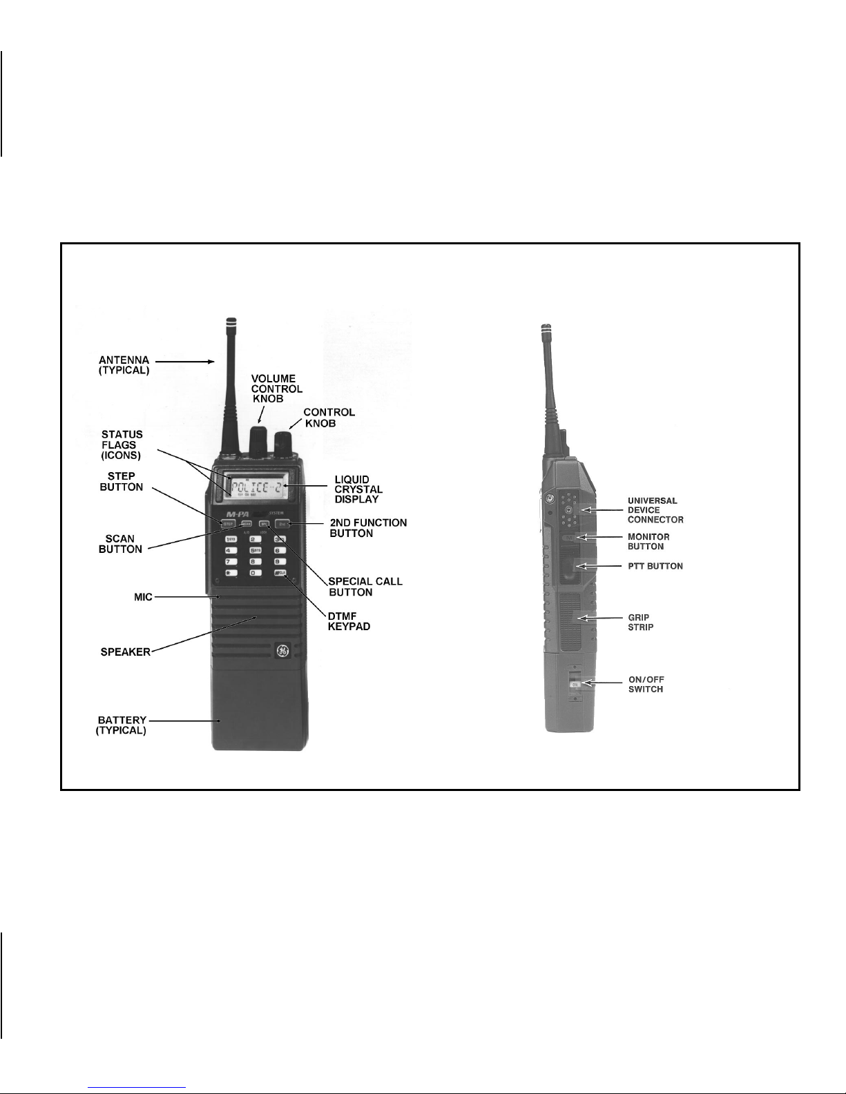
It is housed in a rugged aluminum
case equ ipped with an easy to read alphanumer ic disp lay providing operating
information and radio status. The controls include top mounted rotary Volume
and Control knobs, four Function keys
and a keypad. A recessed Emergency
button permits the use of a single button in sending emergency calls.
OPERATING NOMENCLATURE
CONVENTIONAL OPERATION
Figure 2 - M-PA EDACS System
Personal Radio (Top View)
INTRODUCTION
This manual describes how to use
the M-PA EDACS S yst em Personal Ra-
dios. The M-PA EDACS Select, Scan,
and System Personal Radios are field
programmable microprocessor controlled portable radio designed for Digital
Trunkin g and Co nventional communications.
6
All units on a conventional system
operate through the same radio repeater. Trunked features (such as call
queuing and system scan) a re no t a v ai lable in conventional mode.
TALK-AROUND OPERATION
Also referred to as “direct mode”,
talk-around provides a direct unit-to-unit
short range communications link. It is
intended to maintain communications
Page 7

outside of the main system coverage
area.
TRUNKED OPERATION
Trunked Operation refers to the use
of a set of radio frequency channels by
multiple user groups. By using high
speed digital data your M-PA EDACS
radio goes t o an unused channel when
a call is initiated and will also only respond to calls in the same user group.
In this way conversation privacy between user groups is assured.
SYSTEM (AREA) (Trunked operation
only)
The terms "system" and "areas" are
used interchangeably to refer to the
particular group of station repeaters
curren tly providing service to the radio.
Radios c an be preprogrammed to work
in different systems by changing the
CONTROL Knob position or by pressing the STEP button (for SCAN and
SYSTEM models) depending on radio
programming. (e.g., different systems in
different cities).
GROUP OR SUBFLEET
(Trunked Operation Only)
A group of users share the same
preprogrammed group identification
number in the ir mobile and portable radios. All units in the s ame gr oup will r eceive a di spatc h ca ll placed by any one
unit in the group.
FLEET (Trunked Operation Only)
A fleet of us ers consist s of multiple
groups (subfleets). Radios can be preprogrammed to make fleet calls to simultaneously access multiple user
groups.
AGENCY (Trunked Operation Only)
An agen cy is composed of multiple
fleets. Units can be preprogrammed to
7
Page 8

initiate agency calls to access multiple
fleets.
receive volume to the
desired listening level.
CONTROLS, DISPLAYS AND
CONNECTORS
CONTROLS
ON/OFF The Power ON/OFF
slide switch located on
the side of the battery
pack controls power
from the batter y pack to
the radio. Sliding the
switch up turns on the
radio and exposes the
yellow "ON" indicator.
This will also initiate the
personality self-test.
Sliding the switch down
turns the radio off.
MONITOR In the Trunked mode,
pressing the MONITOR
button enables non-supervisory users to clear
message trunked individual c alls, enter ed digits, and interconnect
calls. Supervisory units
may clear any call regardless of type, transmission or message
trunked. The MONITOR
button is also used to
clear any currently active
callback Status for both
supervisors and non-supervisors.
VOLUME The VOLUME Control
Knob, located o n the top
of the radio, adjusts the
8
In the Conventional
mode, the receiver may
be unsquelched by
pressing and holding the
Page 9

MONITOR button. This
perm its the use r to li sten
to the receiver and adjust the volume control
to the desired level.
When the button is released, the radio mutes
unless a carrier and
channel guard (if enabled) were detected in
the interim.
EMERGENCYThe EMERGENCY but-
(Trunked
mode only)
ton is used to initiate an
emergency call on the
programmed home
group or on the selected
group if no home group
is programmed.
4 KEY CONTROL
(SCAN and SYSTEM MODELS)
CONTROL
KNOB AND
T
System Selection System selection is accomplished with either
the Control knob or the
STEP key depe nding on
the pers onality programming. If the Control knob
is used for System
change, rotating the
knob will change Systems.
If the STEP key is used
for System change, then
pressing the STEP key
will take the radio to the
next system. Pressing
2nd the n STEP will take
the radio to the previous
System. Holding down
the STEP key will result
in repeated operation.
Upon reaching the end
of the System list, the
radio can be programmed to stop or
wrap around to the end
of the list.
9
Page 10
Selection may also be
made by entering the
system number and
pressing the STEP key
(System model only).
Group/Channel Selection -Group selection is
accomplished with either
the Control knob or the
STEP key, depending on
the pers onality programming. If the Control knob
is used for Group
change, rotating the
knob will change
Groups.
Group. Upon reaching
the end of the Group list
the radio can be programmed to stop or
wrap around to the other
end of the list. Selection
may also be made by
entering the group number and pressing the
STEP key (System
mode only).
10
If the STEP key is used
for Group change, then
pressing the STEP key
will take the radio to the
next Group. Pressing
2nd the n STEP will take
the radio to the previous
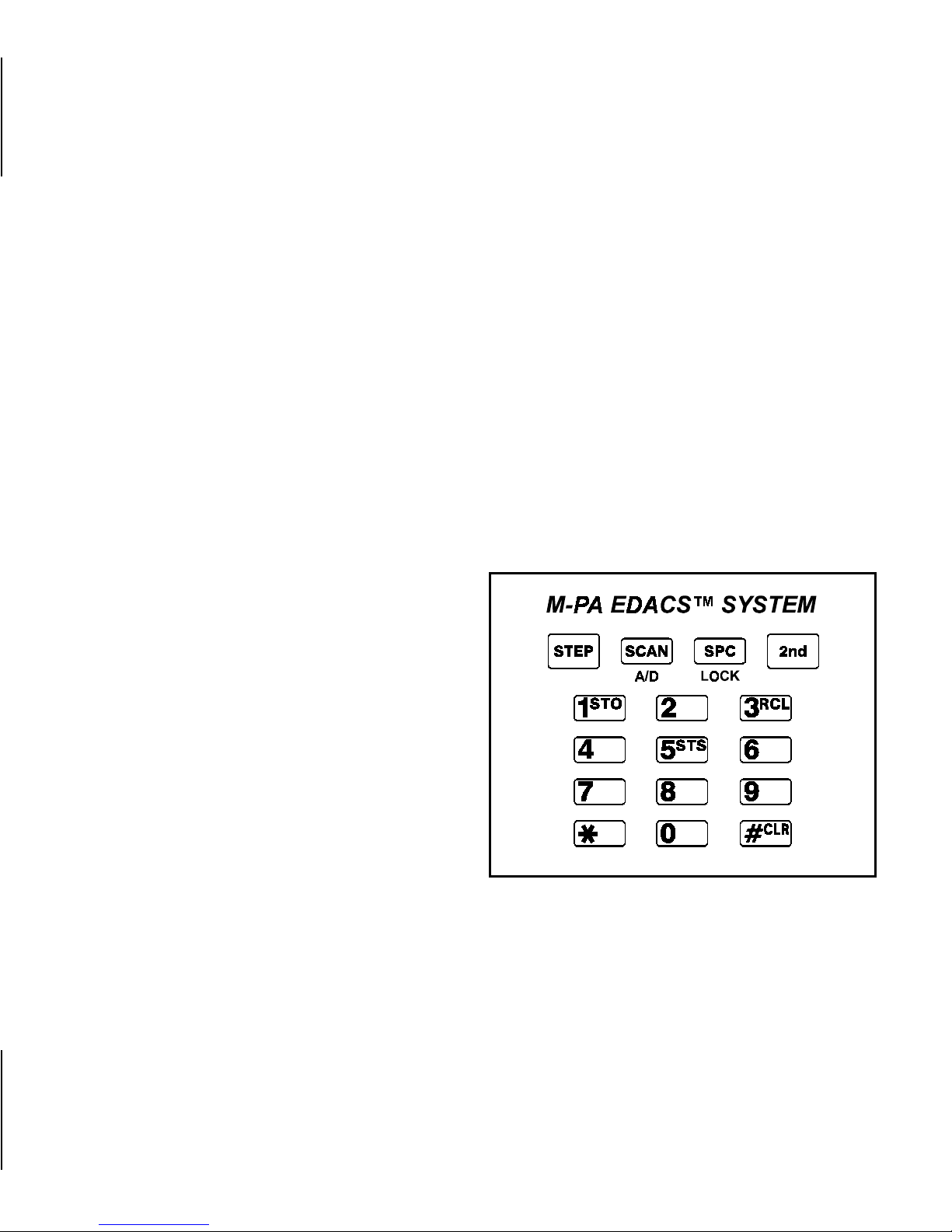
Figure 3 - M-PA System Keypad
Page 11

S
P
The SCAN key turns
Scan operation on or off.
The Special Call (SPC)
key switches operation
between the Group Select Mode and the Special Ca ll mode. Up to 24
special call unless can
be programmed into the
special call set for a
given system (up to 4
sets with 24 special call
entries per radio). The
STEP key is used to
scroll through the list.
SECOND FUNCTION CONTROL
(SCAN And SYSTEM MODELS ONLY)
A/D Pressing the 2nd key fol-
lowed by the Add/Delete
key (A/D) flags the selected group for scan or
deletes the group from
the Scan list.
LOCK Press in g t he 2nd key fol-
lowed by the LOCK key
makes the keypad inoperative, thus preventing
accidental key activation.
Repeating this operation
reenables the keypad.
Selection may also be
made by entering the
Special call entry number and pressing the
SPC key. (Syst em model
only).
SECOND FUNCTION CONTROL
(SYSTEM MODEL ONLY)
The system keypad provides additional capabilities. These capabilities include storage and recall of up to 10
telephone numbers and 10 radio identification numbers, manually sending a
11
Page 12

telephone interconnect call, manually
initiating an individual radio call, and
quick selection of spec ial calls and Systems or groups.
1
The storage function allows you to store a telephone number or radio
ID number.
16382) followed by a
pound sign (#) control
character. Next enter the
storage location (1 to 10)
and press the 2nd and
STO keys. The LCD displays "STORED" for 2
seconds and returns to
its previous state.
12
To store a telephone
number, enter the telephone num ber (up to 29
digits) followed by an asterisk (*) control character. Next enter the
storage location (1 to 10)
and press the 2nd and
STO keys. The LCD displays "STORED" for 2
seconds and returns to
its previous state.
To store an in div idua l radio ID number, enter the
ID number (from 1 to
3
The recall function allows you to recall a telephone number or radio
ID number previously
stored u sing the storage
function. To recall a number, first enter the control digit (* or #) to
indicate whether you are
recalling a telephone
number or a radio ID
number. Next enter the
storage location (1 to
10). Pressing the 2nd
and RCL keys com-
Page 13

pletes the process and
the telep ho ne number or
radio ID number is displayed on the LCD.
Pressing only the 2nd
and RCL keys without
specifying the recall type
or location will recall the
last number that was
stored or recalled.
DISPLAYS
The radio’s Liquid Crystal Display
(LCD) p anel, located on the front of the
radio, provides the use r with an 8 character alphanumeric display and twelve
radio st atus flags located along the top
and bottom of the display panel.
#
Pressing the 2nd key followed by the CLR key
allows you to clear the
last digit entered from
the keypad. If you are
clearing the first digit,
then the display will return to its previous state.
Holding CLR down results in repeated operation.
The alphanumeric display provides
the user with infor mation relating to the
identification of a received or transmitter
call.
The status flags indicate the various operating characteristics of the radio. Only the active flags are displayed.
An explanatio n of the flags is given below.
13
Page 14

EMG Emergen cy indicator - In
trunked mode, the flag is
on steady when the user
initiates or receives an
emergency call.
NC No Control channel -
Steady display indicates
no tru nked control c hannel. Flashing indicates
trunked syst em is in failsoft (supervisory radios
only).
HI High Power status flag -
On indicates the radio is
programmed to transmit
at high power. Off indicates low power.
MSG Message - A flashing
message flag indicates
an individual call has
been received but not
responded to (trunked
mode).
CNV Conventional Mode -
flag indicates that the radio is operating in the
confessional mode.
SPC Sp ecial Ca ll - The flag is
displayed when the Special Call mode is selected (trunked mode).
TX Transmit Status flag -
Flag is on when the radio is transmitting.
BSY Channel Busy indicator -
In the Trunked mode, on
indicates the radio is receiving a call. In the
Conventional mode, on
indicates a carrier is present.
14
Page 15

CG Channel Guard - Dis-
played when Channel
Guard is enabled on the
selected conventional
channel.
External Microphone
External Earphone
External Speaker/Mic
Vehicular Charger
BAT Batter y low - This status
flag indic ates the batter y
pack needs recharging.
S Scan Lis t - Indicates the
selected group/channel
is in the scan list.
SCN Scan - Ind icates radio is
in the Scan mode.
UNIVERSAL DEVICE CONNECTOR
(UDC)
The Universal Device Connector
(UDC) is located on the sid e of the radio above the PTT bar. The M-PA
EDACS radio su ppor t up to 1 6 external
devices. Some of these devices are:
Emergency Lanyard
The UDC is also used by maintenance personnel for programming the
radio.
OPERATION
SELF-TEST
During the power-up sequence, the
radio performs a Personality self-test.
During this test, the radio executes a
set of preprogrammed instructions. At
the star t of the test all segments of the
LCD will be momentarily displayed.
When the radio passes the selftest, it will begin operation on the selected System.
15
Page 16

If the ra dio fails the self-test, an error condition exists and the message
"PERS ERR" will be displayed and a
failure tone is sounded. If this happens,
the radio requires reprogramming or
servicing. A short tone or beep is
sounded if the radio passes the selftest.
CARRIER CONTROL TIMER
(If programmed)
TRUNKED MODE OPERATION
RECEIVING A MESSAGE
1. Slide the ON/OFF switch on the
battery pack to the ON position.
The radio initiates and completes the self-test after which
the System name and "NC"
Status flag are dis played. When
the system control channel is located, the "NC" flag disappears
and the group name is displayed.
2. Set the VOLUME Cont rol to mid
range.
This feature unkeys the transmitter
if the use r exceeds the pre pro grammed
time for continuous transmission and
produces a beeping tone in the speaker
until the PTT switch is released. Releasing PTT resets the timer.
16
3. Use the CONTROL Knob or
STEP key to select the desired
System and/or group (depending on programming). The display indicates the selected
group name.
Page 17

4. The radio is now ready to receive messages.
GROUP CALL - Whe n the radio
5.
receives a group call, it unsquelches on the assigned channel
and lights the "BSY" flag. The
Group name or originator’s ID
(depending on programming) is
displayed.
INDIVIDUAL CALL - If an indi-
6.
vidual call (call directed only to
your radio ) is rec eived, the radio
unsquelches on the assigned
channel and the "BSY" flag
lights. The message "*INDV*" or
originator’s ID is displayed.
If you respond to the call prior to
the programmed call-back time-out,
your call will automatically be directed
to the originating unit.
SENDING A MESSAGE
1. Turn the radio on, set the re-
ceive audio l evel, and select the
desired group as described under TO RECEIVE A MESSAGE.
2. Observe the display for the absence of the "BSY" indicator to
ensure that no one is transmitting on the selected group.
3. Pre ss and h old the PTT bar, the
radio will pe rform the nec essary
signaling required to obtain a
communication channel.
4. Wh en the channe l ha s been acquired, the "TX" and "BSY"
flags are displayed and the
channel access tone is heard.
5. Hold the radio about three
inches from your mouth and
speak normally.
17
Page 18

6. Release the PTT bar when the
transmission is complete, and
listen for any reply.
2. Press the PTT bar, and speak
into the mic rophone in a nor mal
voice.
EMERGENCY OPERATION
Receiving an Emergency Call
1. When the radio receives an
Emergency Channel Assignment, the "EMG" flag is displayed. Follow your standard
emergency procedures.
Sending an Emergency Call
1. For emergency transmission,
press and hold the EMERGENCY button for approximately one second. The radio
transmits an emergency call
message until an Emergency
Channel Assignment is received. Upon receipt the "EMG"
flag is displayed.
3. Release the PTT bar when the
transmission is complete and listen for a reply.
4. When the radio receives a normal group channel assignment,
it will return to the group previously selected.
WIDE AREA ENCODE
This pre pro gra mmed option insures
all system scanning mobiles and portables have time to lock onto the call before the in itiating u nit is all owed to talk.
A three t one ale r t and a shor t delay will
be notice d after keying the un it and before the call originate beep is heard.
This delay occurs only at the first call
transaction, all conversation immediately following will operate at normal
system speed. The delay length will
18
Page 19

vary depending on system operating
parameters.
TELEPHONE INTERCONNECT
This feature al lows you to initiate or
receive telephone calls through your radio if the system is configured for this
operation.
identif ication co de. A mobile or portable
unit can call another particular unit by
programming the receiving unit’s ID into
his radio’s special call set for that system. Each special call may be selectable and accessed through the
CONTROL knob (depending on radio
programming) or through the SPC key
(SCAN and SYSTEM models).
BASE/UNIT OPERATION
This prepro gramm ed option is used
in some fleets so units can only hear
and talk t o a base dispatch unit, not to
other mobiles or portables in the group.
In this mode of operation, when a unit
in a particular group is talking to the
base dispatch unit, all other mobiles
and por tables i n that group will receive
a "System Busy" tone if they try to access the system.
INDIVIDUAL CALL
Every radio in the system is preprogrammed with a unique individual
SYSTEM SCAN
The radio can be preprogrammed
to scan (m onit or acti vity on ) up to three
separate trunked systems and receive
calls on any of these systems.
WIDE AREA SYSTEM SCAN
The unit may be programmed with
a predef ined scan list so that if the current system is lost, the radio will automatically search out and lock to the
next available system in its scan list. If
enabled, the radio will login to the new
system once acquired.
19
Page 20

GROUP SCAN OPERATION
The scan operation is enabled by
pressing the SCAN key, turning on the
"SCN" status flag.
When a group in the scan list receives a ch annel assignment, the radio
unsquelches on the assigned channel
and displ ays the gr oup name. If the radio detects a selected group call, it will
switch to the selected group call and
display the selected group name.
Pressing the PTT while in scan
causes the radio to place the call on the
selected group, as described under TO
SEND A ME SSAGE.
Press the SCAN key to disable
scan operation, the "SCN" flag turns off
and the rad io resumes operation on the
selected group.
GROUP SCAN - MULTIGROUP DECODE (Trunked Operation Only)
This radio can be preprogrammed
to monitor up to 48 se parate groups simultaneously (multi-group decode),
perm itting the user to both monitor and
receive calls from these groups. When a
radio receives a call from one of these
groups, it will "loc k out", a nd no t send or
receive messages from other groups for
a preprogrammed period of 5, 10 or 15
seconds, permitting the user to respond
to the group call. (The radio may also
be preprogrammed for no lock out period). At the end of the "lock out" period,
the radio s ounds two short low pitched
"beeps" and is a gain ready to receive a
call from any of the preprogrammed
groups.
PRIORITY GROUP SCAN
20
If enabled on the radio by the PC
Programmer, Priority Group Scan allows the u s er to s ca n up to 48 separate
Page 21

groups simu lt an eously, with one level of
priority. When the user is receiving a
non-priority group call and a call from
the prior ity group is detected by the radio, the unit will automatically switch to
the priority group call in process.
The priority group call can be defined via the PC Programmer as either
a predetermined group or the currently
selected group.
Adding T o Scan
(System and Scan Models Only)
3. Press 2nd then A/D keys turn-
ing on the "S" flag, the displayed group is now in t he scan
list.
Deleting From Scan
(System and Scan Models Only)
Delete groups from the scan list as
follows:
1. Press the SCAN key if the
"SCN" status flag is on, to turn
scan function off.
Set up (o r add to) the grou ps to be
scanned as follows:
1. Press the SCAN key if the
"SCN" status flag is on, to turn
off scan function.
2. Select the group to be added
using the STEP key or CON-
TROL knob.
2. Select the group to be deleted
using the STEP key or CONTROL knob.
NOTE
If 2nd - A/D keys are pressed
while receiving a scanned call,
the group will be deleted from
the scan list.
21
Page 22

3. Press 2nd then A/D keys turn-
ing off the "S" flag, the displayed group is deleted from the
scan list.
Follow the instructions for sending a
special call.
Sending A Special Call
SPECIAL CALL
Receiving An Individual Call
When an individual call (call directed only to your radio) is received,
the radio u nsquelches on the assigned
channel with the "BSY" flag displayed.
The message "*INDV*" originator’s ID,
or caller’s name is displayed and the
"MSG" flag flashes.
If you respond to the call prior to
the programmed call-back time-out,
your call will automatically be directed
to the originating unit. If you don’t call
back before the call-back time-out, the
"MSG" will remain flashing. To call the
calling u nit back, press SPC. The originator’s ID or name will be displayed.
You may make Special Calls with
your radio t hrough th e Specia l Call feature. Use the following procedure to initiate and complete a Special Call:
1. To make a selection from the
special menu, press and release
the SPC key. An alert tone
sounds, the "SPC" flag lights
and the display changes from
the sele cted group to one of the
special call displays. If no special calls are programmed, the
display indicates "NO SP C" and
the trunked failure tone sounds.
Press the STEP or 2nd-STEP
keys to scroll through the special call menu until the desired
Special Call name appears in
the display.
22
Page 23

2. Press and hold the PTT bar. The
radio performs the necessary
signaling required to obtain a
communication channel. When
the signaling is complete and
the radio is c lear to transmit, the
"TX" flag turns on and the channel access tone sounds.
3. Release the PTT bar when you
are done tal kin g, an d listen for a
reply.
4. When the call is finis hed, the radio remains in the Special Call
menu for a programmed amount
of time. To return to the group
selection, press and release the
SPC key. The radio switches to
the previously selected group.
pad or re call a previously stored
number using the recall function.
The numbe r is displayed on the
LCD.
2. Press and hold the PTT bar. The
radio performs the necessary
signaling required to obtain a
communication channel. When
the signaling is complete, the
"TX" flag l ights a nd the channel
access tone sounds indicating
you are clear to transmit.
3. Speak into the microphone in a
normal voice.
4. Release the PTT bar when
transmission is completed, and
listen for a reply.
Manual Call From Keypad
(System Model Only)
1. En ter the individual radio’s iden-
tification number from the key-
5. Wh en the call is co mpleted, the
LCD w ill c ontinue to display the
radio’s ID until the Special Call
Time-out expires. To return to
the group selection, press and
23
Page 24

release the SPC key. The radio
switches to the previously selected group.
TELEPHONE INTERCONNECT
Yo u may make telephone calls with
your radio t hrough th e Specia l Call feature. Use the following procedure to initiate and complete telephone calls:
1. Pre ss and release the SPC key.
The alert tone sounds, the
"SPC" flag lights and the display changes from the selected
group to one of the special call
displays.
2. Press the STEP or 2nd-STEP
keys to scroll through the special menu, until the desired telephone interconnect display
appears.
3. Pre ss and release the PTT bar.
The radio performs the necessary signaling required to obtain
a communication channel. When
the signaling is complete, the
"BSY" flag turns on and the
channel access tone sounds.
4. Press the PTT bar to speak.
5. To hang-up, press and release
the SPC key. Pressing the
MONITOR button also hangs up
the call and returns radio to
group menu.
Manual T elephone Inter connect
(System Model Only)
1. Enter the telephone number
from the keypa d. The number is
displayed on the LCD. You can
enter up to 31 digits with the last
eight (8) digits displayed. The
last digi t ent ered must be an asterisk (*), indicating the digits
entered are for an interconnect
call. You may also call up a pre-
24
Page 25

viously s tored number using the
recall function.
2. Send the number by pressing
the PTT bar.
The radio performs the necessary signaling required to obtain
a working channel. When the
signaling is successfully completed the "BSY" flag lights, the
channel access tone sounds
and the radi o enters the receive
mode.
If the interconnect signaling is
unsuccessful, the radio returns
to the idle mode and the number
remains displ ayed until the Special Call Time-out expires or another group or system is
selected.
3. When someone answers, press
the PTT bar and speak directly
into the grille on the radio. Re-
lease the PTT bar as soon as
you stop talking. Messages can
not be received when the PTT
bar is pressed.
4. When the conversation is completed, press the SPC to terminate the inter-connection (or
MON/ CLR).
Credit Card Call (System Model
Only)
1. Place a call to the long distance
carrier’s local access number
using the manual interconnect
procedure.
2. When the carrier’s access tone
is heard, enter your credit card
number and press the PTT bar.
The digits are erased from the
display after they are transmitted. You may also send the digits
one at a time by pressing the
PTT after entering each digit.
25
Page 26

3. Continue the call using the man-
ual interconnect call procedures.
VOLUME Control Knob for the
desired listening level.
If the DTMF tones are not recognized, terminate the call by
pressing the SPC key and repeat the process. If the problem
persists, verify software and
hardware associated with DTMF
overdial is operational.
CONVENTIONAL OPERATION
In the Co nventional mode, the user
may select a channel programmed for
conventional use and then communicate on that channel.
RECEIVING A MESSAGE
1. Us e the CONTROL Knob to se-
lect the desired oper ating channel.
2. Press the MONITOR button to
disable squelch. Then adjust the
3. The radio is now ready to receive messages.
SENDING A MESSAGE
1. Tur n the radio on, set the audio
level, and select the desired
channe l as descr ibed under RE-
CEIVING A MESSAGE.
2. Observe the display for the ab-
sence of the "BSY" indicator to
ensure that no one is transmitting on the selected channel.
NEVER interrupt another transmission .
3. Pre ss and h old the PTT bar, the
"TX" flag is displayed. Speak
into the mic rophone in a nor mal
voice. Release the PTT bar
when finished talking, the "TX"
flag goes out and radio returns
to the receive mode.
26
Page 27

ALERT T ONES
This section contains a glossary of
the alert tones and their associated
functions used in your M-PA System.
SELF CHECK TEST
(Trunked and Conventional Modes)
You should hear one short tone or
"beep" shortly after you turn the radio
on. This alert indicates that your radio
has passed a SELF CHECK test, and is
ready for you to send and receive messages. (NOTE: This alert can be disabled by the PC Programmer.)
CALL RECEIVED
(Trunked Operation Only)
A single alert tone is sounded when
you receive a group call. A two tone
aler t is so unded (one high and one low
tone) for an individual call.
CALL ORIGINATE
(Trunked Operation Only)
A short alert tone is sounded whenever you key the unit, (Push-To-Talk
switch is pressed), indicating that your
radio has ac q ui r ed a voice channel. You
can begin sending your message immediately following the tone.
NOTE
The radio can be preprogrammed to
mute the Call Originate and/or Call
Received alert tones. Individual receive alerts cannot be disabled.
CALL QUEUED (Trunked Operation
Only)
If you hear two short, high pitched
tones (beeps) after you key the unit, the
system has placed your request in the
queue. The receiving unit(s) also hear
the to nes, indicating they will receive a
call sho rt ly. If you keep your unit keyed,
your radio will continue to sound the
queue be ep s un ti l t he queue is c lear ed.
27
Page 28

If you should release the PTT button
while in queue, your radio will autokey
whenever a cha nnel becomes available
(see AUTOKEY).
AUTOKEY (Trunked Operation Only)
press the PTT switch. Releasing the
PTT and rekeying init iates a new channel request.
CALL DENIED (Trunked Operation
Only)
When you are placed in queue, the
repeater station calls your unit when a
channel becomes available and automatically keys your transmitter
(autokey) for a short period of time
holding the channel for you. When you
hear the call alert tone, immediately
press the PTT switch to keep the channel and send your message.
SYSTEM BUSY (Trunked Operation
Only)
If you key the radio and hear four
shor t, low pitched tones, the system is
busy (no channels are available at this
time for sending messages, and the
waiting queue is full). The busy tone sequence will be repeated as long as you
If you hear five long low pitched
tones when you key the radio, you are
not a valid user on the sy stem you have
selected.
UNIT DISABLED
(Trunked Operation Only)
When the PTT switch is pressed,
you will hear a continuous low pitched
tone if you r radio has been disabled by
the system. You will not be able to send
or receive any messages until the system re-enables your radio. See your
system operator for more information.
28
Page 29

OUT OF RANGE/SYSTEM IN OPERATIVE (Trunked Operation Only)
resets t he timer and turns the transmitter back on.
Repeated short low pitched tones
heard imme di ately after you key the u n i t
indicates your unit is out of the repeater’s range. These are the same
tones you would hear if you pressed the
MONITOR push-button. If you hear
these "beeps" when you know you are
in range, the s ystem may be off the air
or your portable unit may need servicing.
CARRIER CONTROL TIMER
(Trunked and Conventional Modes)
The Carrier Control Timer aler t is a
long low pitched tone. You will hear the
tone if you excee d the preprogrammed
time for continuous transmission. The
transmitter will shut down shortly after
you hear the tone, interrupting communications. To maintain communications.
release an d re - key the P T T button. This
LOW BATTERY ALERT
(Trunked and Conventional Modes)
If you key the radio and hear a low
pitched, long repeating tone and the
"BAT" flag is on, the battery is discharged and the radio will not transmit
your message. However, the radio will
still be able to receive messages until
the battery is discharged beyond the
point of operation. Replace or recharge
the battery to resume normal operation.
KEY PRESS ALERT
(Trunked and Conventional Modes)
A short tone or "beep" is sounded
to indicate a key has been pressed. If a
shor t low pitched tone is heard after a
key is press ed, this indi cates no action
was taken and a failure occurred.
29
Page 30

OPERA TING TIPS
OPERATING PROCEDURES
The following conditions tend to reduce the effective range of two-way radios and should be avoided whenever
possible.
•• Operating the radio in low areas
of terrain or while under power
lines or bridges.
•• Operating the radio inside of a
vehicle or in a metal or steel
framed building unless using an
outside antenna.
•• Obstructions such as mountains
or buildings between the person
sending and the person receiving
the messages.
In areas where transmission or reception is poor, some improvements
may be obtained by insuring that the
antenna is vertical. Moving a few yards
in another direction or moving to a
higher el evation may also improve communication.
Two-way FM radio systems must
be operated in accordance with the
rules and regulations of the Federal
Communications Commission (FCC).
As an operator of two-way radio
equipment, you must he thoroughly
familiar with the rules that apply to
your particular type of radio operation. Following these rules will help
eliminate confusion and will assure
the most efficient use of existing radio channels. This will result in a
smoothly functioning radio network.
When using your two-way radio, remember these rules:
1. It’s a violation of FCC rules to interrupt any distress or emergency message. As your radio
operates in muc h the same way
as a telephone "party line", always listen and/or observe the
absence of the "BSY" flag to
30
Page 31

make sure that the li ne is clear.
If someone is sending an emergency me s sage -such as r eporting a fire, or asking for help in
an accident - KEEP OFF THE
AIR! Emergency calls have priority over all other messages.
5. Using your radio to send personal messages (except in an
emergency) is a violation of
FCC rules. You may send only
those messages that are essential for the operation of your
business.
2. Use of profane or obscene language is prohibited by federal
law.
3. It is against the law to send false
call letters, or false distress or
emergency messages.
4. The FCC requires that you keep
conversations brief and confine
them to business. To save time,
use code d messages whenever
poss ible.
6. It is against federal law to repeat
or otherwise make known anything you overhear on your radio. Conversations between
others sharing your channel
must be regarded as confidential.
7. The FCC also requires that you
identify yourself at certain specific time s by mean s of your call
letters. Refer to the rules that
apply to your particular type of
operation for the proper procedure.
31
Page 32

REPLACEMENT OF BATTERY
PACKS
To remove the battery pack from
the radio: (refer to Figure 4).
1. Turn the radio off by sliding the
ON/OFF switch to the OFF posi-
tion.
2. Press down on the battery release lat ch and sli de the battery
pack out in the direction of the
release latch.
To connect the battery pack to
the radio: (refer to Figure 5).
1. Ensure that the ON/OFF slide
switch on the battery pack) is in
the OFF position.
2. Align the Battery pack with the
slide grooves and insert into
grooves.
32
Figure 4 - Removing Battery Pack
3. Insert fully into grooves until battery release latch dicks into
place.
INTRINSICALLY SAFE USAGE
Selected personal radios with appropriate factory installed F4 Options
are certified as Intrinsically Safe by the
Page 33

Factory Mutual Research Corporation
for use in Class 1, Division 1 or 2, hazardous locations in the presence of
Groups C and D atmospheres; Non-incentive Class 1, Division 2, hazardous
location s in the presence of Groups A,
B, C, and D atmospheres.
Hazardous locations are defined in
the National Electrical Code. Useful
standards NFPA 437A amid NFPA
437M for the classifications of hazardous area s may be o r de red fr om the National Fire Protection Association,
Batterymarch Park, Quincy, MA 02269.
BATTERY PACKS
Figure 5 - Installing Battery Packs
Only battery packs identified with a
green latch shall be used with a portable radio that is rated and labeled as
Factory Mutual Intrinsically Safe. Use of
nonspecified battery packs voids Factor y Mut ual ap proval. The following batter y pack options are approved for use
in intrinsically safe radios.
PAPA1F Rechargeable Battery Pack,
Extra High Capacity
(Tall Case)
PAPA1G Rechargeable Battery Pack,
High Capacity (Short Case)
33
Page 34

AUDIO ACCESSORIES
The audio ac cessories listed below
are approved for use with intrinsically
safe radios:
Use of audio accessories other
than th ose listed voids the Factor y Mutual approval.
RECHARGING BATTERY PACKS
PAAB1A Headset/Microphone
(high noise environment).
PAAC1J Earpiece Kit.
PAAC1B Emergency Lanyard.
PAAE3R Speaker/Microphone.
PAAE1B Speaker/Microphone
with Emergency Lanyard.
PAAE3T Speaker/Microphone/
Antenna.
PANC1Z Antenna, 896-941 MHz,
Whip.
PAHC1C Belt Clip.
PAHC1D Swivel Mount with Belt Loop.
PAHC3W Case, Leather, with Belt
Loop (Short Case).
PAHC1K Shoulder Strap, Leather,
with Mounting Plate.
PAHC5R Holster, Plastic.
When the battery pack voltage
drops below 6.5 volts DC, the low batter y flag "BAT " is displayed and a 500
Hz tone sounds, indicating the battery
pack needs recharging.
There are several chargers and
charge rates available for charging the
battery packs. For specific instructions
refer to the applicable charger’s operating manual.
REDUCED CAPACITY IN RECHARGEABLE BATTERIES:
Rechargeable batteries in some applicatio ns c an develop a condition of reduced capacity, sometimes called
“Memory Effect”. This condition may occur when:
34
Page 35

1. The battery is continuously overcharged for long periods of time.
2. A re gularly performed duty cycle
which allows the battery to expend only a limited por tion of its
capacity.
Any rechargeable battery showing
signs of reduced capacity should be
careful ly checked before being returned
under warranty or scraped.
RECHARGEABLE BATTERY PACK
DISPOSAL
If the rechargeable battery is only
sparing ly or seldom u sed and is left on
continuous charge for one or two
months at a time, it could experience
reduced capacity. On the first discharging cycle, the output voltage could be
sufficiently lowered to reduce that battery’s hours of useful service.
The most com mo n m ethod of caus ing this limited capacity is regular ly performing short duty cycles; when the
battery is operated so that only a portion (<5 0% ) of its capa city is expended.
This type of of operation can cause the
battery to become temporarily inactive
and how a severe decrease in the ability to deliver a full rated capacity.
The product that you have
purchased contains a rechargeable, recyclable battery. At the end of its useful
life, under various state and
local laws, it may be illegal to dispose of
this battery into the municipal waste
stream. Check with your local solid
waste officials for details in your area
for recycling options or proper disposal.
Call Toll Free 1-800-8-BATTERY for information and/or procedures for returning rechargeable batteries in your state.
35
Page 36

REMOVAL AND REPLACEMENT OF
THE SWIVEL MOUNT
To remove the swivel mount, slide a
flat blade screwdriver underneath the
spring ret aine r a nd t wist (s ee Figure 6).
While tw isting, slide the swivel out from
under the holder .
To replace the swivel mount, place
the end of the swivel in the grooves in
the radio and slide the mount forward
until it snaps in place.
Figure 6 - Removal And Replacement
36
Page 37

PRODUCT SPECIFICATION FOR CE
MARKED EQUIPMENT
The M-PA Portable conforms to the
following Product Specifications.
EUROPEAN STANDARDS:
SUPPLEMENTARY INFORMATION:
At this time, the M-PA portable radio
may not be o perated while in a vehicular
charger in the European Community
since it has not been evaluated for operation in this mode.
Safety: Not Applicable
EMC: prETS 300 279
(August 1995)
TTD: Not Applicable
The M-PA portable radio may be
used in both trunked and conventional
applications.
37
Page 38

WARRANTY
A. Ericsson Inc. (hereinafter "Seller") warrants to the original purchaser for use (hereinafter "Buyer") that Equipment manufactured by Seller
shall be free from defects in material, workmanship and title, and shall conform to its published specifications. With respect to a n y E qu ipment not manufactured by Seller (except for integral parts of Seller’s Equipment to which the warranties set forth above shall apply).
Seller gives no warranty, and only the warr anty, if any, given by the ma n ufacturer shall apply. Batteries are excluded from this warranty but
are warranted under a separate Nickel-Cadmium Battery Warranty .
B. Seller’s obligations set forth in Paragraph C below shall apply only to failures to meet the above warranties (except as to title) occurring
within the following periods of time from date of sale to the Buyer and are conditioned on Buyer’s giving written notice to Seller within
thirty (30) days of such occurr en ce:
1. for fuses, incandescent lamps, vacuum tubes and non-rechargeable batteries, operable on arrival only.
2. for parts and accessories (excep t as no te d in B .1 ) sold b y Se ller ’s Service Parts Operation , nin et y (90) days.
3. f or all other Equipment of Seller’s manufacture, one (1) year.
C. If any Equipment fails to meet the foregoing warranties, Seller shall correct the failure at its option (i) by repairing any defective or dam-
aged part or parts thereof, or (ii) by making available at Seller’ s factory any necessary repa ired or replacement parts. Any repaire d o r replacement part furnished hereunder shall be warranted for the remainder of the warranty period of the Equipment in which it is installed.
Where such failure cannot be corrected by Seller’s reasonable efforts, the parties will negotiate an equitable adjustment in price. Lab or to
perform warranty service will be provided at no charge only for the Equipment covered under Paragraph B.3, and only during the first
three (3) months following the date of sale to the Buyer. Thereafter, labor will be charged at prevailing rates. To be eligible for no-charge
labor, service must be performed by an Authorized Service Center or other Servicer approved for these purposes either at its place of
business during normal business hours, for mobile or personal equipment, or at the Buyer’ s location, for fixed location equipmen t. Service
on fixed location equipment more than thirty (30) miles from the Service Center or other approved Ser vicer’s place of business will include a charge for transportation.
D. Seller’s obligations under Paragraph C shall not apply to any Equipment, or part thereof, which (i) has been modified or otherwise altered
other than pursuant to Seller’s written instructions or written a pprov al or, (ii) is normally consumed in operation or, (iii) has a normal lif e inherently shorter than the warranty periods specified in Paragraph B, or ( iv) i s n ot p ro pe rl y stored, installed, used, ma intained or re pa ire d,
or, (v) ha s bee n sub j ect ed to an y ot he r kind of mi su se or det rime nt al exposure, or has be en in v olved in an accident.
E. The precedi ng paragraphs set forth the exclusive remedies for claims (except as to title) based upon defects in or nonconformity of the
Equipment, whether the claim is in contract, warranty, tort (including negligence), strict liability or otherwise, and however instituted. Upon
the expiration of the warranty per iod, all such liability shall terminate. The foregoing warranties are exclusive and in lieu of all other warranties, whether oral, written, expresse d, implied or stat utory. NO IMPLIED OR STA TUTORY W ARRANTIES OF MERCHANTABILITY OR
FITNESS FOR PARTICULAR PURPOSE SHALL APPLY. IN NO EVENT SHALL THE SELLER BE LIABLE FOR ANY INCIDENTAL,
CONSEQUENTIAL, SPECIAL, INDIRECT OR EXEMPLARY DAMA GES .
This warranty applies only within the United States.
1-800-592-7711 (Outside USA, 804-592-7711)
38
ECX-362S
Page 39

NICKEL-CADMIUM BATTERY WARRANTY
A. Ericsson Inc. (hereinafter "Seller") warrants to the original purchaser for use (hereinafter "Buyer") that
nickel-cadmiu m batteries supplied by Seller shall be free from defects in material and workmanship,
and sha ll conform to its pu blished spec ification s for a period of twelve (12) months from the d ate of
purchase.
B. For purpo ses of this warra nty, b atteries shall be deemed defective if (1) the battery capacity is less
than 80% of rated capacity, or (2) the batter y develops leakage.
C. If any bat ter y fails to mee t the foregoing warranty, Seller shall correct the failure by issuing a replace-
ment batt er y upon re ceipt o f the de fective batter y at a n Authorized S ervi ce Center (ASC). To o btain
the name and address of an ASC, ask your salesperson, consult the Yellow Pages, or call the number
printed at the bottom of this page.
D. Replacement batteries shall be warranted only for the remaining unexpired warranty period of the
original battery. This warranty becomes v oid if:
(1) The battery has been subjected to any kind of misuse, detrimental exposure, or has been in volved
in an accident.
(2) The bat tery is used in eq uipment or ser vice other than the radio equipment for which it is speci-
fied.
E. The prece ding para graphs set forth the exclusive remedies for claims (except as to title) base d upon
defects in or no n-conformit y of any batter y, whether the claim is in contract, warranty, tort (including
negligence), strict liability or otherwise, and however instituted. Upon the expiration of the warranty period, a ll such liability shall terminate. The foregoing warranties are exclusive and in lieu of all other
warranties, whether oral, written, expressed, implied or statutory . NO IMPLIED OR STATUTORY WARRANTI ES OF MERCHANTABILITY OR FITNESS FOR PARTICULAR PURPOSE SHALL APPLY. IN
NO EVENT SHALL TH E COMPANY BE LI ABLE FOR ANY INCI DENTAL, CONSEQUENTIAL, SPECIAL, INDIRECT OR EXEMPLARY DAMAGES.
This warranty applies only within the United States.
1-800-592-7711 (Outside USA, 804-592-7711)
ECX-841C
39
Page 40

Police
State Police
Fire
Poison Control
Ambulance
Life Saving and
Rescue Squad
EMERGENCY NUMBERS
Ericsson Inc.
Private Radio Systems
Mountain Vie w Road
L y nch b ur g, Virginia 2450 2
1-800-592-7711 (Outside USA, 804-592-7711) Printed in U.S.A.
 Loading...