

Page 1

MINI-LINK BAS
Technical Description
Page 2

Ericsson is the leading provider
in the new telecom world,
with communications solutions
that combine telecom and datacom technologies
with freedom of mobility for the user.
With more than 100,000 employees in 140 countries,
Ericsson simplifies communications for its Customers
- network operators, service providers,
enterprises and consumers -
the world over.
Ericsson Information on Demand Database can be
addressed at: http://www.ericsson.com
We continuously develop and improve our products and therefore
reserve the right to alter technical details without notice.
Ericsson Microwave Systems AB
Microwave Radio Division
S-431 84 Mölndal
SWEDEN
Telephone: +46 31 747 00 00
Fax: +46 31 27 72 25
EN/LZB 111 0542 P2B
© Ericsson Microwave Systems AB 2000
Designed and developed by
Ericsson Lab Italy
R&D Global Product Center
via Cadorna 73, 20090 Vimodrone, Milan
ITALY
Page 3

1 MINI-LINK BAS
EN/LZB 111 0542 P2B Technical Description
MINI-LINK BAS
Technical Description
Copyright Ericsson 2000
Page 4

MINI-LINK BAS 2
Technical Description EN/LZB 111 0542 P2B
Foreword
The customer documentation includes all information and documents
necessary for a basic knowledge of Ericsson systems.
The above said documentation has its own code number and release;
the latter is subject to changes whenever eventual updates may occur.
The customer documentation is subdivided into the following
manuals:
• AT Installation Manual
• Installation Manual
• Operation and Maintenance Manual
• Planning and Engineering Manual
• Product Catalogue
• Technical Description
The purpose of this description is to support the reader with detailed
information on the product from technical and functional points of
view.
It supplies all information necessary to understand equipment
operation and technical characteristics. This document is addressed to
the network planner and operation personnel who will find the
information they are interested in.
Use of any trademark in this document is not intended in any way to
infringe on the rights of the trademark holder.
Page 5

3 MINI-LINK BAS
EN/LZB 111 0542 P2B Technical Description
Preface
For more information, please refer to the MINI-LINK BAS Product
Catalogue.
You may also contact your Ericsson representative or the area sales
manager for your country at:
Ericsson Microwave Systems AB
Microwave Radio Division
S-431 84 Mölndal
SWEDEN
Telephone: +46 31 747 00 00
Fax: +46 31 27 72 25
Please contact your Ericsson representative for latest details and data.
The specifications or configuration contained in this document are
subject to change without notice due to continuous design
improvement.
If there is any conflict between this document and Compliance
statements, the latter will supersede this document.
Please refer to the “Information Revision” document for details about
the updating level of the present description.
The MINI-LINK BAS and the relative Customer documentation have
been designed and developed by:
Ericsson Lab Italy
R&D Global Product Center
via Cadorna 73
20090 Vimodrone
Milan
ITALY.
Page 6

MINI-LINK BAS 4
Technical Description EN/LZB 111 0542 P2B
Contents
1 Introduction............................. 1-1
1.1 General Information..................................1-2
1.2 Manual Structure.......................................1-2
1.3 General Overview.....................................1-3
1.3.1 Opportunities.....................................................1-3
1.3.2 Product Benefits................................................1-4
1.4 Terminology..............................................1-6
2 System Description ................ 2-1
2.1 Overview...................................................2-2
2.2 System Components.................................2-4
2.2.1 AT .....................................................................2-5
2.2.1.1 FlexNU................................................................2-6
2.2.1.2 ODU....................................................................2-6
2.2.1.3 ACT.....................................................................2-6
2.2.2 RN.....................................................................2-6
2.2.2.1 R-AAS.................................................................2-8
2.2.2.2 ODU..................................................................2-10
2.2.3 C-AAS.............................................................2-11
2.2.4 Control and Management................................2-11
2.2.4.1 CP.....................................................................2-11
2.2.4.2 EM.....................................................................2-11
2.3 Configuration Limits................................2-12
2.4 System Interfaces...................................2-12
2.4.1 Intra-System Interfaces...................................2-12
2.4.2 Customer Service Interfaces...........................2-13
2.4.3 Local Exchange/ISP Interfaces.......................2-14
3 Network Architecture.............. 3-1
3.1 Introduction...............................................3-2
3.2 SN.............................................................3-3
3.2.1 SN R-AAS Stand-alone.....................................3-3
3.2.2 SN C-AAS.........................................................3-4
3.2.3 Generic MINI-LINK BAS Network......................3-6
3.2.4 SN connection to CP and EM............................3-7
3.2.5 Examples of an Overall Network.......................3-8
3.3 System Synchronisation ...........................3-9
3.4 Traffic Routing........................................3-10
Page 7

5 MINI-LINK BAS
EN/LZB 111 0542 P2B Technical Description
3.5 Typical Network Applications...................3-11
4 End-User Services...................4-1
4.1 Introduction...............................................4-2
4.2 Data Communication.................................4-3
4.2.1 Ethernet Frames Encapsulation According
to RFC 1483......................................................4-4
4.3 CE Services..............................................4-6
5 Physical and MAC Layers.......5-1
5.1 Introduction...............................................5-2
5.2 Physical Layer...........................................5-3
5.2.1 Media Control Loops .........................................5-5
5.2.1.1 Amplitude Control Loop....................................... 5-6
5.2.1.2 Frequency Control Loop...................................... 5-6
5.2.1.3 Modulation Index RCL, Uplink and Downlink....... 5-7
5.2.1.4 Clock Phase RCL, Uplink only............................5-7
5.2.2 Radio Link Adaptation .......................................5-8
5.2.3 Modulation.........................................................5-8
5.3 RAUs ........................................................5-9
5.3.1 Block Diagram.................................................5-10
5.3.1.1 Trans mi tter On/Off Switch................................. 5-13
5.4 LLC Layer ...............................................5-14
5.4.1 TDMA/TDM Framing .......................................5-14
5.4.1.1 Downlink TDM Fram e.......................................5-14
5.4.1.2 Uplink TDMA Frame......................................... 5-15
5.4.2 Frame Alignment.............................................5-17
5.4.3 Scrambling.......................................................5-17
5.4.4 FEC.................................................................5-17
5.4.5 Performance Monitoring..................................5-18
5.5 MAC Layer..............................................5-20
5.5.1 Sign-On...........................................................5-22
5.5.2 Distance Ranging............................................5-22
5.5.3 Radio Bandwidth Limitation.............................5-23
5.6 Processing Flow......................................5-24
5.6.1 Downlink Processing Flow...............................5-24
5.6.2 Uplink Processing Flow...................................5-25
5.6.3 RC Cells Insertion............................................5-26
6 Management and Control6-1
6.1 Introduction...............................................6-2
6.2 Management System................................6-3
6.3 Control Architecture ..................................6-4
6.3.1 Hierarchy...........................................................6-4
Page 8

MINI-LINK BAS 6
Technical Description EN/LZB 111 0542 P2B
6.3.2 Board Relay ......................................................6-5
6.3.3 ICS/ATM Connection Rules..............................6-5
6.3.3.1 Configuration Requirements................................6-5
6.3.3.2 Interface Requirements.......................................6-6
6.4 EM............................................................6-9
6.4.1 Basic Platform.................................................6-10
6.4.2 Generic Services.............................................6-12
6.4.3 Specific Services.............................................6-14
6.5 CP...........................................................6-15
6.5.1 Interface Handlers ...........................................6-16
6.5.2 Main Applications............................................6-16
6.5.2.1 Connection Handler...........................................6-17
6.5.2.2 Equipment Handler............................................6-17
6.5.2.3 Alarm Handler ...................................................6-18
6.5.3 HH (Device Handlers).....................................6-18
6.5.4 MRS & MRI.....................................................6-19
6.6 Equipment Management.........................6-20
6.6.1 Equipment Hardware Configuration................6-20
6.6.2 Equipment Software Configuration..................6-20
6.6.3 Equipment Supervisioning...............................6-21
6.6.4 Equipment Errors and Error Handling.............6-22
6.6.5 Equipment Audit..............................................6-22
6.7 Connection Management........................6-23
6.7.1 Connection Configuration................................6-23
6.7.2 Cross Connection Re establishment...............6-24
6.7.3 Connection Supervisi on..................................6-24
6.8 Alarm and Event Management ................6-25
6.8.1 Alarm Correlation............................................6-25
6.8.2 Alarm Suppression..........................................6-25
6.8.3 Active Alarm List .............................................6-25
6.8.4 Alarm and Event Log.......................................6-26
6.8.5 Alarm Severity .................................................6-26
6.9 Performance Management......................6-27
6.10 Database Management...........................6-27
6.10.1 Persistent Data................................................6-27
6.10.2 Backup and Restore........................................6-28
6.10.3 Atomicity of Transactions................................6-28
6.11 Internal Communication..........................6-29
6.11.1 Communication between EM and CP.............6-29
6.11.2 Communication between CP and DP..............6-29
6.12 Recovery Procedures .............................6-31
6.12.1 Initial Start.......................................................6-31
6.12.2 Cold Restart....................................................6-31
6.12.2.1 System Cold Restart..........................................6-31
6.12.2.2 Board Cold Restart............................................6-32
6.12.3 Hot Restart......................................................6-32
Page 9

7 MINI-LINK BAS
EN/LZB 111 0542 P2B Technical Description
7 ATM Transport and
Multiplexing ..............................7-1
7.1 Introduction...............................................7-2
7.2 Virtual Connections...................................7-3
7.2.1 VP/VC Connection Plan....................................7-4
7.2.2 Use of VPI/VCI Values ......................................7-4
7.3 Service Categories....................................7-6
7.3.1 Connection Admission Control..........................7-6
7.4 R-AAS and C-AAS (CE Shelf)...................7-7
7.5 FlexNU......................................................7-8
7.6 ATM Fault Management............................7-8
8 Equipment Practice and
Power ........................................8-1
8.1 Introduction...............................................8-2
8.2 Hub Site....................................................8-2
8.2.1 R-AAS, Radio-ATM Access Shelf......................8-2
8.2.1.1 PSU.................................................................... 8-3
8.2.1.2 Fan Unit.............................................................. 8-3
8.2.2 RAU...................................................................8-4
8.2.3 Antenna.............................................................8-5
8.2.3.1 Antenna for Point-to-Multipoint Connection ......... 8-5
8.2.3.2 Antenna for Point-to-Point Connection................ 8-6
8.3 AT Site......................................................8-8
8.3.1 FlexNU...............................................................8-8
8.3.2 RAU...................................................................8-9
8.3.3 Antenna.............................................................8-9
8.4 Core ATM – C-AAS (CE Shelf)................8-10
8.4.1 Front Access Shelf ..........................................8-10
8.4.2 Rear Access Shelf...........................................8-11
8.4.3 POU.................................................................8-12
8.4.4 Fan Unit for Front Access AAS........................8-12
8.4.5 Fan Unit for Rear Access AAS........................8-13
8.5 Control and Management........................8-14
8.5.1 EM...................................................................8-14
8.5.2 CP ...................................................................8-15
8.6 PDU........................................................8-15
8.7 Cabinets/Racks.......................................8-16
8.7.1 Front Access Central Office.............................8-16
8.7.2 Rear Access Central Office.............................8-20
Page 10

MINI-LINK BAS 8
Technical Description EN/LZB 111 0542 P2B
9 O&M Facilities......................... 9-1
9.1 Introduction...............................................9-2
9.1.1 Communication Channels.................................9-2
9.1.2 AT Setup...........................................................9-3
9.2 Fault Detection..........................................9-3
9.2.1 Alarms...............................................................9-3
9.2.2 Events...............................................................9-8
9.3 Test Loops................................................9-9
9.3.1 RN Near-End Loops..........................................9-9
9.3.2 AT Near-End Loops ..........................................9-9
9.3.3 AT Far-End Loops...........................................9-10
9.4 Performance Monitoring..........................9-11
9.4.1 Signals Monitoring...........................................9-12
9.5 Unit Replacement...................................9-12
9.6 Local Supervision Interface.....................9-13
9.7 System Upgrade.....................................9-16
9.7.1 Install SW Upgrade File...................................9-17
9.7.2 Download Modules..........................................9-17
9.7.3 Install New Management System....................9-17
9.7.4 Stop CP...........................................................9-17
9.7.5 Install New CP Software..................................9-17
9.7.6 Upgrade Network Database............................9-17
9.7.7 Start Control Processor in “Upgrade mode”....9-18
9.7.8 Execute Upgrade ............................................9-18
9.7.9 Restart Control Processor...............................9-19
9.7.10 Software Rollback...........................................9-19
9.7.10.1 Case A ..............................................................9-19
9.7.10.2 Case B ..............................................................9-20
9.7.10.3 Case C..............................................................9-20
10 Technical Data ...................... 10-1
10.1 System Parameters ................................10-2
10.1.1 Frequency Range............................................10-2
10.1.2 Transmitter Performance.................................10-4
10.1.3 Receiver Performance ....................................10-6
10.1.4 Transmission Technology...............................10-7
10.2 Intermediate Frequency..........................10-8
10.3 System Features.....................................10-9
10.4 Power Supply........................................10-11
10.5 Antenna Data........................................10-12
10.5.1 Radio Node Antennas...................................10-12
10.5.2 AT Antennas .................................................10-13
10.6 Environmental Requirements................10-14
10.6.1 Cabinets/Racks/Frames................................10-14
10.6.2 Power Distribution.........................................10-14
Page 11

9 MINI-LINK BAS
EN/LZB 111 0542 P2B Technical Description
10.6.3 EMC ..............................................................10-14
10.6.4 Alarms...........................................................10-14
10.7 Characteristics ......................................10-15
10.7.1 Central Office.................................................10-15
10.7.2 AT..................................................................10-16
10.7.3 ODU ..............................................................10-17
10.8 Miscellaneous Features........................10-20
11 Index.......................................11-1
11.1 Index.......................................................11-2
Page 12

MINI-LINK BAS 10
Technical Description EN/LZB 111 0542 P2B
Page 13

1-1 MINI-LINK BAS
EN/LZB 111 0542 P2B Technical Description
Introduction
Page 14

MINI-LINK BAS 1-2
Technical Description EN/LZB 111 0542 P2B
1.1 General Information
The new fields for application of microwave radio links introduce
more demanding functional requirements as well as stricter
requirements on operational performance. The transmission quality in
terms of acceptable bit error ratio, availability, and so on is improved,
as well as the spectral characteristics in order to permit effective
utilization of the available bandwidth.
The scope of requirements in the form of directives, standards and
recommendations issued by national and international organizations is
constantly widening.
The MINI-LINK BAS meets these requirements. Performance data
meets or surpasses the detailed requirements specified for this type of
equipment.
1.2 Manual Structure
The Technical Description was prepared in order to satisfy the
customer’s need for information on the technical features of his
equipment; it is composed of the following parts:
Contents
It includes the general contents of the chapters.
Introduction
It consists of this section that describes in short the contents of the
various parts composing the description and the list of acronyms and
abbreviations.
Chapters
They supply all information necessary to understand equipment
operation and technical characteristics. These are addressed to the
network planner and operation personnel who will find the
information they are interested in.
Page 15

1-3 MINI-LINK BAS
EN/LZB 111 0542 P2B Technical Description
1.3 General Overview
The MINI-LINK BAS -Broadband Access System- product family is
member of Ericsson’s large and powerful product line for
telecommunication. The combined expertise of Ericsson, covering
switching, cellular technology, radio and networking, means
excellence in turnkey project management.
It is more than just an Asynchronous Transfer Mode (ATM) crossconnect featured by a point-to-multipoint microwave radio. It is a
complete system, including hardware, software, experience and
competence. The MINI-LINK BAS integrates fully with existing
telecom access networks, adding new levels of flexibility. It has
proved to be a reliable communication medium, a highly competitive
alternative to copper and fibre cable.
The MINI-LINK BAS is a natural step in Ericsson's product
development program, in response to new requirements from a
growing market and is based on more than 20 years’ experience of
microwave links.
Ericsson designers and engineers remain vigilant, seeking new
technology and developments to keep MINI-LINK BAS at the
forefront of microwave communications. Advanced Technology,
constant product development of powerful functions, operational
reliability and quality have resulted in the MINI-LINK BAS.
MINI-LINK BAS is a product for point-to-multipoint and point-topoint connections, carrying multimedia traffic services and is designed
primarily to meet increased demands for more efficient transmission
systems in access networks.
1.3.1 Opportunities
The worldwide deregulation of the local loop market, the emergence
of new wireless technologies, and an increased demand for new
services, has created a great market opportunity for existing and new
competitive access service providers.
Small and medium sized businesses have an increasing demand for
data oriented services such as high-speed Internet/Intranet access,
LAN-LAN interconnect, Internet Protocol (IP) services and T1/E1
leased line connections.
MINI-LINK BAS offers the possibility to satisfy these needs,
providing the medium for convergence between telecommunication,
and datacom/ Information Technology (IT) systems.
Ericsson experience in building world class radio products coupled
with clear market drivers such as Local Multipoint Distribution
System (LMDS), has lead Ericsson to define and develop our next
generation ATM based digital microwave radio systems, for
broadband radio access. The system is initially targeted for the
business community supporting a large range of multimedia services.
Page 16
MINI-LINK BAS 1-4
Technical Description EN/LZB 111 0542 P2B
A well designed wireless broadband access system, enables operators
to provide rapid, cost efficient, flexible and reliable broadband access,
without the need of a cost prohibitive and complex fiber access
infrastructure. The system is efficient in both areas with high and
low/medium penetration since the system is featured by a scaleable
“pay as you grow” architecture.
IP
Services
Telephony
ATM
Leased
Line
Radio
Nodes
Access
Termination
Ethernet
and/or
E1/T1
interfaces
Indoor
Indoor
Indoor
Indoor
Indoor
Indoor
HUB
Outdoor
Outdoor
Figure 1-1 General Applications for the BAS
1.3.2 Product Benefits
The MINI-LINK BAS offers, to name a few, the following features:
• true Fast Dynamic Capacity Allocation (F-DCA) for data
services;
• port-to-port, intra-Hub, Local Area Network (LAN) and Private
Branch Exchange (PBX) interconnections without the use of core
resources;
• symmetrical broadband air-interface, independent in both
directions;
• cost-efficient scaleable broadband access solutions (pay as you
grow);
• rapid deployment and provisioning;
• reduced dependence on existing facilities;
• integration/convergence of different types of services such as IP
traffic and telephony traffic.
The radio design is based on the same platform that is being
developed for the immensely successful and reliable MINI-LINK
family, deployed in more than 100 countries.
Page 17

1-5 MINI-LINK BAS
EN/LZB 111 0542 P2B Technical Description
This digital microwave family has shown exceptional reliability with
actual Mean Time Between Failures (MTBF) figures exceeding 30
years, thanks to a quality oriented high volume production, with a
current production capacity exceeding 100,000 units per year. In the
MINI-LINK BAS the new multi-chip module improves the reliability
and simplifies production even further.
• The design is compact and integrated. The radio and antenna
form an integrated outdoor part;
• clean-cut concept; the outdoor part holds all frequency-dependent
units and the indoor part holds all traffic management units;
• single coaxial cable interconnection between outdoor and indoor
parts;
• software-aided Access Terminal (AT) configuration and setup;
• centralized operation and maintenance system by means of the
EM (Element Manager);
• high system gain and spectrum utilization with an advanced
modulation process and coding;
• high MTBF figures of 20–30 years.
Page 18

MINI-LINK BAS 1-6
Technical Description EN/LZB 111 0542 P2B
1.4 Terminology
AAL ATM Adaptation Layer
ACT AT Craft Tool
ANSI American National Standards Institute
API Application Programming Interface
ASK Amplitude Shift Keying
AT Access Terminal
AT Access Termination
ATM Asynchronous Transfer Mode
ATPC Automatic Transmit Power Control
BAS Broadband Access System
BBER Background Block Error Ratio
C-AAS Concentration Shelf
CB Channel Bank
CBR Constant Bit Rate
CE Circuit Emulation
CE-AAS Circuit Emulation Shelf
CE Board Network side Circuit Emulation card
CEPT Conference on European Post and Telegraph
CP Control Processor
CPE Customer Premise Equipment
C-QPSK Constant envelope offset Quadrature Phase
Shift Keying
CRC Cyclic Redundancy Check
DP Device Processor
EBER Excessive Bit Error Ratio
EIA Electronic Industries Association
EM Element Manager
ESR Error Second Ratio
ET Exchange Terminal
ETSI European Telecommunication Standard
Institute
FAS Frame Alignment Signal
Page 19

1-7 MINI-LINK BAS
EN/LZB 111 0542 P2B Technical Description
FAW Frame Alignment Word
FEC Forward Error Correction
FCC Federal Communication Commission
FCS Frame Checking Sequence
F-DCA Fast Dynamic Capacity Allocation
FDD Frequency Division Duplex
FlexNU Flexible Network Unit
FPROM Flash Programmable Read Only Memory
GUI Graphical User Interface
HH Hardware Handler
HP-OV Hewlett Packard OpenView
HTTP Hyper Text Transport Protocol
ICS Internal Communication System
IEC International Electrotechnical Commission
IF Intermediate Frequency
IP Internet Protocol
IRCC Internally Radio Communication Channel
ISDN Integrated Services Digital Network
ISP Internet Service Provider
IT Information Technology
ITU International Telecommunications Union
LAN Local Area Network
LLC Logical Link Control
LMDS Local Multipoint Distribution System
LOS Line-of-Sight
MAC Media Access Control
MCM Multi-Chip Module
MIB Managed Information Base
MMIC Microwave Monolithic Integrated Circuit
MRI Managed Resource Interface
MRS Managed Resource Server
MS Management System
MTBF Mean Time Between Failures
Page 20

MINI-LINK BAS 1-8
Technical Description EN/LZB 111 0542 P2B
NCU Node Control Unit
NE Network Element
NNM Network Node Manager
NU Network Unit
ODU Outdoor Unit
OTP Open Telecom Platform
OSI Open Systems Interconnection
PABX Private Automatic Branch Exchange
PBA Printed Board Assembly
PBX Private Branch Exchange
PDH Plesiochronous Digital Hierarchy
PDU Power Distribution Unit
PID Process Identification Number
PLL Phase Locked Loop
PMP Point to Multi Point
POTS Plain Old Telephone Service
POU Power Unit
PRC Primary Reference Clock
PSTN Public Switching Telephone Network
PSU Power Supply Unit
PVC Permanent Virtual Circuit
QoS Quality of Service
R-AAS Radio Shelf (Radio ATM Access Subrack)
RAI Remote Alarm Indication
RC Radio Control channel
RCL Radio Control Loop
RDI Remote Defect Indication
RF Radio Frequency
RN Radio Node
RAU Radio Unit
RSSI Received Signal Strength Indication
RTD Round Trip Delay
SC Service Configuration
Page 21

1-9 MINI-LINK BAS
EN/LZB 111 0542 P2B Technical Description
SDH Synchronous Digital Hierarchy
SESR Severely Error Second Ratio
SN System Node
SNI Service Network Interface
SONET Synchronous Optical Network
STA Spanning Tree Algorithm
SU Service Unit (AT side)
TDM Time Division Multiplex
TDMA Time Division Multiple Access
TMN Telecommunication Management Network
UAT Unavailability
UBR Unspecified Bit Rate
UDT Unstructured Data Transfer
UF Uplink Efficiency
UNI User Network Interface
VC Virtual Channel
VCO Voltage Control Oscillator
VCTCXO Voltage Controlled Temperature Compesated
Crystal Oscillator
VoIP Voice over Internet Protocol
VP Virtual Path
WAN Wide Area Network
WBAS Wireless Broadband Access System
Page 22

MINI-LINK BAS 1-10
Technical Description EN/LZB 111 0542 P2B
Page 23

2-1 MINI-LINK BAS
EN/LZB 111 0542 P2B Technical Description
System Description
Page 24

MINI-LINK BAS 2-2
Technical Description EN/LZB 111 0542 P2B
2.1 Overview
The MINI-LINK BAS integrates ATM transport and microwave
broadband technologies. This permits the system to efficiently use the
carrier bandwidth to support a wide range of medium to high-speed
services. It is a complete end-to-end solution from customer service
terminals, to IP/ATM/PSTN backbone equipment and management
systems. It assures the quality, availability and security that Ericsson
customers have come to depend on for over a century.
The MINI-LINK BAS consists of customer located Access
Terminations (ATs), communicating with Radio Nodes (RNs).
User traffic is either transported to the customer premises through a
dedicated point-to-point connection, for longer radio reach, or in a
point-to-multipoint configuration. The latter provides an efficient use
of available spectrum sharing the air interface capacity among many
customers and allowing the use of statistical multiplexing over the
radio interface.
The system communicates with ATM and PSTN backbones via a
variety of standard interfaces, from E1/T1 to OC-3/STM-1, 155 Mbps.
ATs support a wide variety of services, from PBX interconnections to
LAN to LAN interconnect and Internet access over different types of
interfaces such as E1/T1 and Ethernet 10/100BaseT.
The customer located ATs are designed with “hot plug-in” service
interface boards for different service requirements. So new services
are easily added without any impact on other services. ATs are also
designed with remote program capability so that settings can be
changed without the need for a visit from a service engineer at the
customer premises.
The MINI-LINK BAS utilises a Constant envelope offset-Quadrature
Phase Shift Keying/Time Division Multiple Access/Frequency
Division Duplex (C-QPSK/TDMA/FDD) scheme.
C-QPSK is a robust modulation scheme that delivers exceptional
Carrier to Interference (C/I) performance and a healthy link budget
that is required in a fully built out system.
The TDM/TDMA solution allows to efficiently support the fast
dynamics in bursty packet switched data networks (IP traffic) via
statistical multiplexing and F-DCA. This results in a very compact and
cost effective solution.
The MINI-LINK BAS uses applicable frequency spectrum such as:
• 24.5-26.5 GHz band in Europe
• 27.5-28.35 GHz in the US LMDS “A” band
• 31.0-31.30 GHz in the US LMDS “B” band
Page 25

2-3 MINI-LINK BAS
EN/LZB 111 0542 P2B Technical Description
MINI-LINK BAS supports 28 MHz Channelling achieving a capacity
over the air interface of 37.5 Mbps in both directions.
The MINI-LINK BAS follows a cellular deployment structure where
multiple cells support a footprint over a geographical area. Each cell is
comprised of a Hub with multiple RNs equipped with
sector/directional antennas for point-to-multipoint and point-to-point
connections.
The ATs require a Line-of-Sight (LOS) path toward the Hub and can
be located anywhere within the sector coverage area, typically up to 6
km for point-to-multipoint access; up to 10 km for point-to-point
access; the actual distance depends on the operating frequency and
rain zone.
Page 26
MINI-LINK BAS 2-4
Technical Description EN/LZB 111 0542 P2B
2.2 System Components
The MINI-LINK BAS consists of the following components:
1. AT
− In Door Unit (IDU): FlexNU
− Out Door Unit (ODU): Radio and antenna
2. RNs
− Indoor NCU
− ODU: Radio and antenna
3. C-AAS
4. Control and management
− CP
− EM
RNs are housed in R-AAS. A Radio Hub site can contain one or more
RNs plugged into one or more R-AASs. The multiple shelves can be
co-located or remote from each other.
EM
CP
ATM
Backbone
Server
Nodes &
Router
Element Manager Service
Configuration, Fault and
Perfomance Management
C-AAS
(CE Shelf)
R-AAS
FlexNU
ATs
FlexNU
Figure 2-1 MINI-LINK BAS Generic Network
Page 27

2-5 MINI-LINK BAS
EN/LZB 111 0542 P2B Technical Description
2.2.1 AT
AT is composed by:
− IDU: FlexNU
− ODU: Radio and the antenna
AT is located at the edge of the network close to the subscriber
providing an interface between the MINI-LINK BAS network and the
subscriber equipment.
Each AT is assigned to a RN and receives downlink, broadcast traffic
from that RN using the TDM scheme. AT transmits uplink traffic to
the RN in a TDMA fashion sharing the total RN capacity, 37.5 Mbps,
with the ATs.
Network Unit (NU)
Service
Interface
Units
Modem
Unit
User
Radio
Unit
User
Antenna
Figure 2-2 AT Block Diagram
CE_NU_E1/T1, SU Ethernet
Modem Board
Ethernet
POTS
PABX
FlexNU
User Radio Unit
Figure 2-3 AT
Page 28

MINI-LINK BAS 2-6
Technical Description EN/LZB 111 0542 P2B
2.2.1.1 FlexNU
FlexNU is the indoor part of the AT. It is connected to the ODU with
an IF coaxial cable, as shown in the Figure 2-3.
The FlexNU, which can house Modem board and Service Units (SUs),
features an active backplane on which the Media Access Control
(MAC) functionality is implemented.
FlexNU supports different types of services at each subscriber node by
means of SU boards. Two types of SUs are currently available:
• CE-SU E1/T1 with 2 interfaces per board
• 10/100BaseT-SU with 2 interfaces per board
Up to four SUs can be inserted as plug-in modules in the FlexNU.
This gives the FlexNU service flexibility and upgrade capability. In
addition to the plug-in SUs, the FlexNU is equipped with a power
supply unit, 110/220 Vac, and a built-in Ethernet 10BaseT interface
usable for maintenance operations.
2.2.1.2 ODU
The ODU consists of a Radio and a directional antenna ”Low Profile”
parabolic type, 0.20 m., integrated within its casing.
Optionally an integrated 0.60 m antenna is available.
2.2.1.3 ACT
The AT Craft Tool (ACT) is a software application that resides in the
AT. By means of an external notebook, working in VT-100 emulation,
the ACT is used for local maintenance of the AT. The connectivity is
provided by a RS232 interface available on the FlexNU front plate.
The installation or maintenance personnel can read or set configurable
parameters locally within the AT, for example the radio frequency, the
AT and RN identification numbers.
Via ACT it is possible to execute local software download and
download swap command can be independently executed.
2.2.2 RN
The Radio Node (RN) consists of an ODU and an IDU. The ODU is
made of a Radio and a Node Antenna. The Node Antenna is either a
directional antenna for point-to-point applications or a sector antenna
for point-to-multipoint applications.
Page 29

2-7 MINI-LINK BAS
EN/LZB 111 0542 P2B Technical Description
A RN, equipped with a sector antenna, creates a sector carrier that
typically covers an area up to 6 km in radius. Multiple sector carriers
can be used to increase the capacity within a sector and multiple
sectors can be used to cover a complete cell area of a Radio Hub.
Node
Control
Unit
Node
Radio
Unit
Node
Antenna
Radio Node (RN)
=
Node
Control
Unit
MAC
+
Modem
Figure 2-4 RN Block Diagram
The Node Antenna and the Radio are encased in a weatherproof
outdoor mounted casing. The Radio is highly integrated and connected
to the IDU via an Intermediate Frequency (IF) coaxial cable.
The microwave parts incorporate Ericsson’s unique Microwave
Monolithic Integrated Circuit (MMIC) technology that supports
integration of a complete receiver and transmitter into a single multichip module, thus reducing the size of the ODU (see Figure 2-5).
MMIC technology also guarantees extremely high reliability and is
suitable for high-volume production.
The IDU is the NCU of the RN and it consists of Modem and MAC
board sandwiched in a single plug-in unit.
The Modem board provides the IF interface towards the outdoor
mounted radio and contains all modulating/demodulating functions.
The Modem is also in charge to maintain the radio links, providing
control loops for frequency, timing and transmitter power.
MAC functionality rules the traffic demands toward and from the
ATs. MAC is based on very fast protocol and scheduling mechanism
that grant capacity request in less than 1 msec.
The F-DCA feature of the MAC protocol affords very high statistical
gain so that Radio capacity is used in a very efficient way.
The MAC board connects to the ATM bus on the backplane of the RAAS.
The downering cell rate managed by a RN is 78000 cells/s. This is a
net capacity in downlink and a gross capacity in the uplink.
In order to calculate the net capacity in uplink it must consider the
overhead, which is necessary to handle traffic queues status in each
AT. The overhead depends on the number of ATs per RN and on the
polling period.
In the following table the capacity reduction is given for a defaultpolling period, 80 slots, versus the number of ATs per RN. The
Uplink Efficiency (UF) varies from 0.96 to 0.75.
The throughput at the application level, both CE and Ethernet will
decrease because of the ATM and AAL1, AAL5 overhead.
Page 30

MINI-LINK BAS 2-8
Technical Description EN/LZB 111 0542 P2B
Moreover some capacity is allocated for control purpose and Physical
Layer preservation. In the table are reported the max number of
unstructured E1/T1 connections versus the number of ATs.
ATs/RN UF (%) E1/RN T1/RN
1 to 8 0.96 14 18
9 to 16 0.93 13 18
17 to 24 0.90 13 18
25 to 32 0.87 13 17
33 to 40 0.84 13 17
41 to 48 0.81 12 17
49 to 56 0.78 12 16
57 to 64 0.75 12 16
2.2.2.1 R-AAS
The R-AAS is an indoor mounted subrack that can accommodate up
to six plug-in NCUs (Modem + MAC). Each NCU is connected to an
ODU, which is dedicated to a RN in a sector.
R-AAS can also house ET and CE-SNI boards. ET boards provide
Wide Area Network (WAN) connectivity towards ATM backbone, IP
router, C-AAS. CE-SNI boards provide connectivity towards PSTN.
R-AAS provides a total of 17 board slots, which are distributed
according to the following scheme.
• Slot 1: ET board, any type 155, 45 or 34 Mbps
An ET board shall be always present for Cellbus
arbitration.
• Slot 2, 3: 2 CE-boards
• Slot 4, 5: 1 NCU or 2 CE-boards
• Slot 6, 7: 1 NCU or 2 CE-boards
• Slot 8, 9: 1 NCU or 2 CE-boards
• Slot 10, 11: 1 NCU
• Slot 12, 13: 1 NCU
• Slot 14, 15: 1 NCU
• Slot 16: POU
• Slot 17: POU
Depending on the configuration, a R-AAS can host up to 6 RNs, or up
to 8 CE-boards that can terminate 32 E1/T1 interface connections.
Page 31

2-9 MINI-LINK BAS
EN/LZB 111 0542 P2B Technical Description
R-AAS can support different configurations:
Number of RNs
Number of CE
boards
Number of E1/T1
interfaces
62 8
54 16
46 24
3, 2, 1 8 32
In principle, a fully equipped R-AAS with 6 RNs, could cover up to 6
* 64 = 384 ATs. However, in order to optimise the overall
performance of the system, it is recommended not to exceed 128 ATs
per R-AAS.
The R-AAS backplane can handle up to 530 Mbps, providing crossconnect functionality between ATs covered by RNs inserted into the
same R-AAS.
P
S
U
P
S
U
FAN
R-AAS
SUB-ID
TX/RX
SLOT2
TX/RX
SLOT3
TX/RX
SLOT4
TX/RX
SLOT5
TX/RX
SLOT6
TX/RX
SLOT7
TX/RX
SLOT8
TX/RX
SLOT9
Figure 2-5 ODU and the R-AAS
R-AAS provides an ATM cross-connection capability through a
distributed bus architecture named Cellbus. Each NCU, ET, CE-SNI
boards access the bus through a CUBIT-PRO device.
ET board in slot 1 will acts as bus arbiter.
The traffic from the NCU/RNs is cross connected on the Cellbus to
allowing very flexible interconnection between two ATs in a RN.
ATs can be connected not only to the backbone networks but also
among them:
• ATs in a RN (User to User connection)
• From one RN to another RN (User to User connection)
Page 32

MINI-LINK BAS 2-10
Technical Description EN/LZB 111 0542 P2B
• From a RN to a ATM switch, through an ET155 interface board;
OC-3/ STM-1 (User to Service connection)
• From a RN to a PSTN switch, through a CE-SNI E1/T1 interface
board (User to Service connection)
Point-to-multipoint
connections
Point-to-point
connections
Node
Control
Unit(s)
CE_SNI_E1/T1
SDH/SONET/ATM
Cell-BUS
Radio Shelf
Figure 2-6 R-AAS
The interfaces at the customer premises, in our case at the ATs, are
referred as User interfaces, whereas interfaces toward backbone
network are referred as Service interfaces.
Subscriber traffic can be connected in a User to Service connection,
from the subscriber to the backbone network, or from User to User.
For User to Service connections, CE traffic from various RN, can be
terminated in the R-AAS using the CE-SNI (E1/T1) board. As an
alternative it can be connected through an ET155 to an ATM network
and then terminated in an external C-AAS (CE Shelf) using CE-SNI
(E1/T1) boards or in other equipment supporting standard CE
termination functions.
Data traffic related to an AT Ethernet interface, similarly, can be
connected in a User to Service connection from the RNs through an
ET155 to an ATM switch. For User to User connections (data or CE),
the R-AAS provides a through path from RN to RN.
2.2.2.2 ODU
ODU contains Node Antenna and Radio. The ODU is connected to the
NCU through a coaxial cable.
The Node Antenna used for point-to-multipoint applications is sector
antenna, highly directive in elevation. For point-to-point applications
the antenna that is used is a directive ”Low Profile” parabolic type
antenna.
Page 33

2-11 MINI-LINK BAS
EN/LZB 111 0542 P2B Technical Description
2.2.3 C-AAS
C-AAS is aimed to host CE terminations towards PSTN. C-AAS is
mostly equipped with CE-SNI boards.
The C-AAS has 19 board slots which usage is report below:
Slot 1: ET boards
Slots 2-17: CE boards or ET boards
Slots 18-19: Two redundant power supplies, operating in load sharing
mode
The ET board, in slot 1, shall be always present as performs Cellbus
arbitration. Typical configuration foresees one ET board, for
connection toward R-AAS or backbone network and up to 16 CE-SNI
boards for connection toward PSTN.
Other configurations, with a greater number of ET boards, are
allowed.
The C-AAS provides an ATM cross-connect functionality through
Cellbus, as in R-AAS.
2.2.4 Control and Management
2.2.4.1 CP
The CP constitutes the agent that carries out all of the EM User
commands, acts as the repository for the system database, and
oversees control of the overall system. It is a UNIX based shelf
mounted processor. CP can be either co-located with the R-AAS,
C-AAS or at a remote location.
The CP is physically connected through a SDH/SONET link at OC3/STM-1 Rate. The ATM switch multiplexes the CP control message
traffic and subscriber traffic together for interfacing to the ET155
boards.
It is possible to connect the CP either to each C-AAS (CE Shelf) or RAAS shelf using ATM connection or directly to ET in slot 1.
One CP can control a number of shelves, C-AAS (CE Shelf) and RAAS, and their subtended equipment, that are radios and ATs.
2.2.4.2 EM
The EM operates on a standalone UNIX based workstation. The EM
interfaces to the CP using a 10BaseT connection. One EM can manage
shelves controlled by several CPs.
The EM can be co-located or remote from the CP that it manages.
Page 34

MINI-LINK BAS 2-12
Technical Description EN/LZB 111 0542 P2B
2.3 Configuration Limits
MINI-LINK BAS components have the following configuration
limits:
• EM can support to 10 CPs.
• 1 CP can control up to 128 ATs and support up to 30 SNs.
• 1 RN supports up to 64 ATs.
• 1 AT supports up to 4 Ethernet SUs or CE SUs.
2.4 System Interfaces
The system includes several primary physical interfaces.
2.4.1 Intra-System Interfaces
ET155 ATM
• 155 Mbps, IR, SONET STS-3c (Bellcore GR-253-CORE)/ S1.1
SDH STM-1 (ITU-T G.957)
• Full duplex
• Single mode optical interfaces
Radio Interface
• Channel spacing: 28 MHz
• Air capacity: 37.5 Mbps gross bit rate, full duplex using C-QPSK
modulation scheme
• Frequency bands:
− ETSI 26 GHz
− LMDS A 28GHz
− LMDS B 31 GHz
Note: The formal Type Approved certification has been obtained
for the given frequencies.
There are also other frequencies that have been
introduced, apply to the local Business Manager for more
information.
• Duplex distance:
− 1008 GHz for ETSI
Page 35

2-13 MINI-LINK BAS
EN/LZB 111 0542 P2B Technical Description
− 420 MHz for LMDS
ET34/45 ATM
• E3/T3, 34/45 Mbps
• Full duplex
• Electrical interface
• DS3 direct and PLCP mapping available
2.4.2 Customer Service Interfaces
10BaseT/100BaseT Ethernet
• IEEE 802.3/Ethernet, 10/100 Mbps
• Half duplex and full duplex
• Electrical interface with Multiprotocol over ATM Adaptation
Layer 5 encapsulation (RFC 1483)
Note: This functionality minimizes the system impact on
supporting LANs.
2xDS1 – CE_NU_T1 SU
• ITU G.703/704
• TDM
• 1.544 Mbps
• Full duplex
• Electrical interface
• Unstructured CE service, synchronous and plesiochronous
2xE1 - CE_NU_E1 SU
• ITU G.703/704
• TDM
• 2.048 Mbps
• Full duplex
• Electrical interface
• Unstructured CE service, synchronous and plesiochronous
10BaseT NU built-in
• IEEE 802.3/Ethernet
Page 36

MINI-LINK BAS 2-14
Technical Description EN/LZB 111 0542 P2B
• 10 Mbps
• Half duplex
• Electrical interface with Multiprotocol Over ATM Adaptation
Layer 5 encapsulation (RFC 1483)
• Operation and Maintenance access only
2.4.3 Local Exchange/ISP Interfaces
ET155 ATM
• 155 Mbps, IR, SONET STS-3c (Bellcore GR-253-CORE)/ S1.1
SDH STM1 (ITU-T G.957)
• Full duplex
• Single/multi mode optical interfaces
ET34/45 ATM
• E3/T3, 34/45 Mbps
• Full duplex
• Electrical interface
• DS3 direct and PLCP mapping available
4xDS1 - CE_SNI_T1
• ITU G.703/704
• TDM
• 1.544 Mbps
• Full duplex
• Electrical interface, unstructured CE service, synchronous and
plesiochronous
4xE1 - CE_SNI_E1
• ITU G.703/704
• TDM
• 2.048 Mbps
• Full duplex
• Electrical interface, unstructured CE service, synchronous and
plesiochronous
Page 37

3-1 MINI-LINK BAS
EN/LZB 111 0542 P2B Technical Description
Network
Architecture
Page 38

MINI-LINK BAS 3-2
Technical Description EN/LZB 111 0542 P2B
3.1 Introduction
MINI-LINK BAS is a scaleable system that allows building up access
networks ranging from very small to very large configuration.
MINI-LINK BAS network can be tailored to very different scenarios
in terms of subscribers or traffic density.
This chapter describes basic configurations and the rules to build large
configurations. Network synchronisation options are described.
Remote and local connection of Control and Management
components, CP and EM, are described as well.
Last some typical network applications are shown in Paragraph 3.5.
Page 39

3-3 MINI-LINK BAS
EN/LZB 111 0542 P2B Technical Description
3.2 SN
The basic MINI-LINK BAS network is constitued by a single R-AAS
and its served access terminals.
This basic network supports all services and can be connected both to
an ATM backbone network and a PSTN network through STM-1, E1,
T1, E3, DS3 interfaces.
A large access network can be made of several basic networks,
according to a cellular deployment. In a MINI-LINK BAS network,
geographically spread, the use of ET1/T1 links for connection of RAAS to the PSTN would be quite expensive because of the high
number of links and their length.
MINI-LINK BAS provides an effective solution by the use of a CAAS close to the PSTN. Traffic collected from the R-AASs can be
transported toward the C-AASs through a few high capacities STM-1
connections.
This will result in a very cost-effective solution.
The R-AAS and the C-AAS are named, in the Control and
Management perspective, SNs. SNs can be connected to CP and EM
either in local or in remote mode.
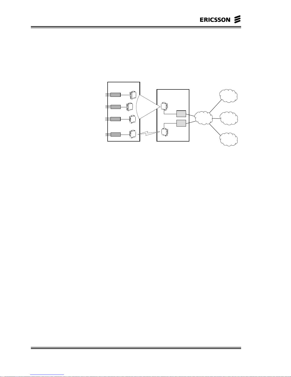
3.2.1 SN R-AAS Stand-alone
This is the basic MINI-LINK BAS configuration made of only one
R-AAS.
ATM network
AT
AT
AT
ET board
R-AAS
Always Slot 1 (CellBus Master)
RN Control Unit
boards
CE boards
System Node R-AAS stand-alone
One PVC for each ETxx,
CE board and NCU
CP
PSTN
EM
HUB
Figure 3–1 SN R-AAS Stand-alone
Page 40

MINI-LINK BAS 3-4
Technical Description EN/LZB 111 0542 P2B
The R-AAS is directly connected to the backbone networks, both
ATM and PSTN. CE boards and ET boards can be mixed in a rather
free way in the subrack.
This is the typical SN architecture where mainly data traffic is handled
and only few CE E1/T1 connections are terminated.
In the Figure 3–1 the R-AAS is remotely connected to the CP, through
the backbone ATM network. The local CP connection is supported as
well.
3.2.2 SN C-AAS
The C-AAS SN addresses a specific functionality in a MINI-LINK
BAS network: the termination high number of CE emulation
connections.
The typical application is therefore in large MINI-LINK BAS
networks where several SN R-AAS are present and a high number of
CE connections are transported and terminated within the system.
ATM network
System Node C-AAS (CE Shelf) stand-alone
One PVC for each ETxx,
CE board and NCU
CP
C-AAS
(CE Shelf)
CE boards
ET
PSTN
SN R-AAS
stand-alone
SN R-AAS
stand-alone
SN R-AAS
stand-alone
EM
HUB
HUB
HUB
Figure 3–2 SN C-AAS Stand-Alone
When a large number of E1/T1 connections is terminated within the
system, due to the R-AAS limitations and capacity availability, proper
C-AAS has to be used. All CE traffic coming from each R-AAS can
be terminated in one or a set of C-AAS.
Theoretically, in principle the C-AAS has 16 slots available to host
CE boards for CE traffic collection from the R-AAS through the
backbone ATM network. In practice, the bandwidth budget has to be
analysed when defining the actual structure of this SN.
Page 41

3-5 MINI-LINK BAS
EN/LZB 111 0542 P2B Technical Description
In fact, the C-AAS has here to terminated the CBR (typically E1/T1)
traffic. The ET link capacity and the number of CE boards, in terms of
E1/T1 ports, constitute the bottleneck of such a configuration.
Moreover, it must be noted that the intermediate configurations are
possible. In fact, as the CE boards can be hosted both into the R-AAS
and into the C-AAS, additional PSTN links could be obtained using
available slots in the R-AAS directly.
This configuration is well suited when the physical connection points
with the PSTN are co-located with the C-AAS, while the R-AAS is
remote.
The C-AAS is basically equipped with CE boards and one ET board
connected to the ATM backbone, in slot 1.
Page 42

MINI-LINK BAS 3-6
Technical Description EN/LZB 111 0542 P2B
3.2.3 Generic MINI-LINK BAS Network
The generic MINI-LINK BAS network is made of several SN.
Each SN can be seen as a totally independent, tree-structured sub-
network, having the direct access to each backbone network and
offering end-user services.
The SNs are mutually independent, that is, there is no traffic crossing
the SN boundaries toward another SN without passing through the
backbone network. Each CP can manage a number of different System
Nodes (SNs). The numbers of SNs each CP can manage is mainly
dependent on the total number of ATs.
A single EM can manage up to 10 CPs. In the management
perspective the CP is the agent whilst the EM is the manager. The subnetwork controlled by the CP is therefore referred as NE.
A single CP can control up to 30 SNs. However, in order to optimise
the control architecture performance, it is recommended not to exceed
128 ATs per CP; therefore, the real number of CP to be deployed
strictly depends on the topology of each SN, and less than 30 SNs
could be actually allowed under the same CP.
Backbone Network
(ATM, PSTN, data network, ...)
..................................................................................
CP
SNSNSNSNSN
CPE CPE CPE
EM
Network Element
Figure 3–3 Generic MINI-LINK BAS Network
Page 43

3-7 MINI-LINK BAS
EN/LZB 111 0542 P2B Technical Description
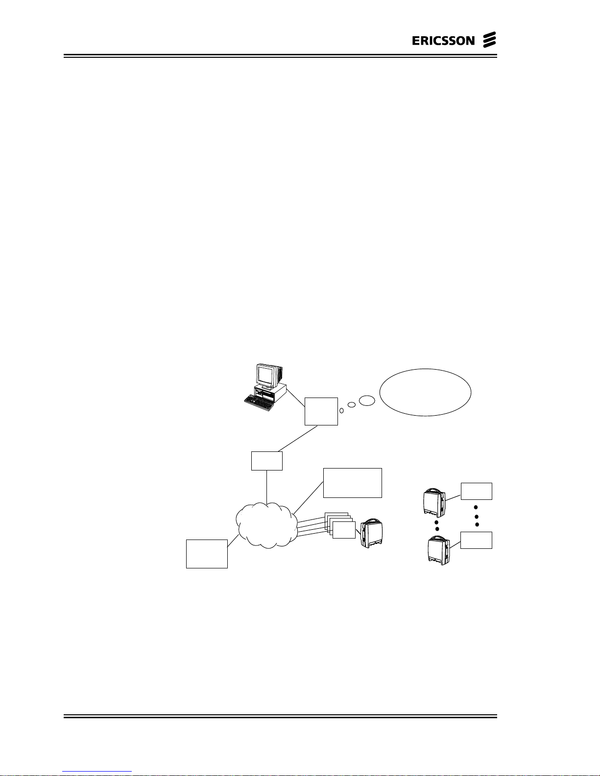
3.2.4 SN connection to CP and EM
The CP is equipped with ATM interface at STM-1 line rate, therefore
can be connected to SNs through ATM virtual connections, is either a
remote or local mode.
In the remote connection mode, the CP is connected to the ATM
backbone network and virtual connection are set up in the ATM
network to reach SN, as shown in the Figure 3–4.
CP can be locally connected to a SN as well. In such a case the CP is
directly connected through an optical fibre to the ET 155 board
housed in the slot 1 of shelves, either R-AAS or C-AAS.
The ET 155 board exploited for CP local connection is no longer
available for traffic.
Only one SN can be managed by the CP local mode because of the
uniqueness of the physical interface.
CPs are connected to EM through an Ethernet interface on an Ethernet
LAN. External device performing Ethernet bridging are needed in
case the EM is remotely located respect the CP.
C-AAS (CE Shelf) or R-AAS
ET155
ATM adapter
CP
slot 1
ATM network
C-AAS (CE Shelf) or R-AAS
ET155
In-band CP communication
channel directly on the STM-1
link
ATM adapter
CP
slot 1
B
A
Figure 3–4 CP-SN Connection through ATM Network
Up to 10 CPs can be managed by an EM. An estimated bandwidth of
128 kbps per CP is needed.
Page 44

MINI-LINK BAS 3-8
Technical Description EN/LZB 111 0542 P2B
3.2.5 Examples of an Overall Network
The following diagrams show some different network applications for
the MINI-LINK BAS.
NU
Ethernet
E1/T1
PBX
ET NCU NCU
ET CE CEET
ET155-ET34/45
R-AAS
ET NCU NCU
R-AAS
ET155-ET34/45
C-AAS
(CE Shelf)
FlexNU
AT
PBX
FlexNU
AT
Ethernet
E1/T1
PBX
ATM
Network
PSTN
Network
CE
CP
EM
MS
Figure 3-5 Network Example with R-AAS and C-AAS
Ethernet
E1/T1
PBX
ET NCU
NCU
R-AAS
ET NCU NCU
R-AAS
FlexNU
AT
PBX
AT
Ethernet
E1/T1
PBX
CE
CE
ET155
CP
EM
ATM
Network
PSTN
Network
FlexNU
MS
Figure 3-6 Network Example with R-AAS
Page 45

3-9 MINI-LINK BAS
EN/LZB 111 0542 P2B Technical Description
3.3 System Synchronisation
MINI-LINK BAS access network needs to be synchronized to the
backbone networks in order to interoperate correctly with them.
Interoperation with a PSTN is strictly related to the services provided
which imply isochronous operations and timing transparency from the
Local Exchange till Customer Premises Equipments (CPEs).
Even the SDH/ATM backbone network requires synchronous
operation, at least at link level. The timing of PSTN and SDH/ATM
backbone derive from a Primary Reference Clock (PRC) – eventually
this PRC clock could be unique.
In order to face different network scenarios the system allows the
choice of any port in the system – both PDH synchronous and SDH –
for synchronization purpose. In principle, because of the synchronous
CES support, the best choice is to use synchronous PDH references as
isochronous operation where the PSTN network is inherently assured.
The use of SDH ports for synchronization is also a suitable choice
since once timing of SDH network and PSTN network are traceable to
the same PRC. If it is not the case and the two networks are traceable
to separate PRC, byte slips would be experienced for the PDH service,
which rate is anyway limited to less than 1 slip every 72 days.
Slips are not due to the system behaviour but are due to the
plesiochronous operation of the backbone networks.
Asynchronous PDH ports are not suitable for network synchronization
and their use is not allowed for synchronization purpose.
The lack of a network reference will make the system operate in the
free running mode: the port selected for synchronization will keep
synchronizing the system exploiting the on board internal reference,
that features a Stratum 4 clock accuracy, that is better than 32 ppm.
The port selected for synchronization is monitored against failures,
synchronization specific alarms are reported to the operator to allow
manual recovery of the failure. Guidelines and procedures are given in
the proper section of the user documentation.
The system does not foresee any dedicated port for network
synchronization from office clock distributors.
Page 46

MINI-LINK BAS 3-10
Technical Description EN/LZB 111 0542 P2B
3.4 Traffic Routing
MINI-LINK BAS, as any access network, allows the set-up of traffic
connection from the customer, User interface, to the backbone
networks, Service interface.
Due to a cross connection capability in R-AAS, C-AAS, AT-to-AT
connections are allowed without resorting to the backbone network.
Internal traffic is generated, whenever AT-to-AT connections are
established within a sector, without exploiting R-AAS resources, or
within a single R-AAS domain, without exploiting ATM Network
resources.
LAN
PBX
FlexNU
FlexNU
LAN
LAN
PBX
FlexNU
R-AAS
ATM
C-AAS
(CE Shelf)
LAN
PBX
FlexNU
R-AAS
PSTN
Telephony
ROUTER
Internet
10/100BaseT
CE T1/E1
RN internal traffic
R-AAS internal traffic
MINI-LINK BAS
Figure 3–7 MINI-LINK BAS with AT-to-AT Connections
Page 47

3-11 MINI-LINK BAS
EN/LZB 111 0542 P2B Technical Description
3.5 Typical Network Applications
Due to its flexible ATM based platform and its F-DCA technology, is
a highly competitive solution for delivering services in the access
network.
Traditional telephony service can be supported by the MINI-LINK
BAS as shown in Figure 3-8. Typically, small and medium businesses
have a PBX that uses either analogue or digital lines. A digital PBX
that uses E1/T1 trunks can interface directly to the CE-SU (E1/T1) AT
interfaces. In order to support analogue telephony services, the
operator can augment the AT functionality with a Channel Bank (CB).
ATM PVC links the AT’s E1/T1 interface to a CE-SNI E1/T1
interface in the R-AAS or in a C-AAS, which in its turn is connected
to the PSTN. Note that the MINI-LINK BAS can also support an
intra-Hub port-to-port connection, depicted in Hub 1 in the diagram.
For local leased line interconnection applications this can reduce the
load on the ATM mux/switch and other associated central office
equipment.
PBX
AT
AT
AT
AT
Radio
Shelf
C-AAS
(CE Shelf)
AT
CB
AT
AT
AT
RN
RN
ATM
Radio
Shelf
CB
PSTN
HUB 1
HUB 2
CB = Channel Bank
PBX = Private Branching Exchange
AT = Access Termination
RN = Radio Node
Analog
PABX
PBX
Figure 3-8 System Deployed for Telephony (PBX-PSTN, PBX-
PBX)
An alternative solution to the conventional voice transportation is
offered by the Voice over IP (VoIP) technology. An example of how
the MINI-LINK BAS can support VoIP is shown in Figure 3-9. In
such a scenario the subscriber’s IP packets, containing telephony
information, interface with the MINI-LINK BAS through an AT’s
10BaseT interface and are then carried along with other IP services.
To support VoIP services, the operating company or subscriber must
use an external VoIP gateway.
This solution gives the subscriber and operating company the option
to select between traditional voice or datacom and VoIP services
converged according to their needs.
Page 48

MINI-LINK BAS 3-12
Technical Description EN/LZB 111 0542 P2B
PBX
AT
AT
AT
AT
Radio
Shelf
AT
AT
AT
AT
RN
RN
ATM
Radio
Shelf
HUB 1
HUB 2
R = Router
G/W = H. 323 Gateway
AT = Access Termination
RN = Radio Node
GK = Gatekeeper
G/W
R
LAN
LAN
R
G/W
G/K
G/W
INTERNET
PSTN
PSTN
H. 323 Terminal
Figure 3-9 System Deployed for IP Telephony (PBX-PSTN, PBX-
H.323 terminal)
Subscriber’s datacom traffic is bridged at Ethernet interface to provide
a demarcation point between the CPE LAN and the public network.
Typically a router can provide the operator with many options for
multiple ISP access, billing and security for Internet and Intranet
solutions.
AT
AT
AT
AT
Radio
Shelf
AT
AT
AT
AT
RN
RN
ATM
Radio
Shelf
HUB 1
HUB 2
R = Router
AT = Access Termination
RN = Radio Node
R
LAN
LAN
R2
R
R3
ISP 1
R3
ISP 2
Figure 3-10 System Deployed for Data Traffic and Multiple IP
Selection
Page 49

4-1 MINI-LINK BAS
EN/LZB 111 0542 P2B Technical Description
End-User Services
Page 50

MINI-LINK BAS 4-2
Technical Description EN/LZB 111 0542 P2B
4.1 Introduction
Small and medium sized offices require support for data and
telephony traffic interconnection. Data traffic can be either between
the end-user LANs or between a LAN and the Internet.
In a similar way the telephony traffic can be either between end-user
PBXs or between a PBX and the PSTN.
These different interconnection cases are shown in Figure 4-1.
PBX
LAN
Router
PBX
Router
Internet
LAN
MINI-LINK BAS
PSTN
ATM
LAN
PABX
LAN
Leased Digital
(E1/T1)
Leased Lines
Figure 4-1 Different Traffic Interconnections Needs
Traditionally the services described above have been offered to the
end-users as leased lines based on the telephony network
infrastructure with a permanently allocated capacity and a granularity
of 64 Kbps.
MINI-LINK BAS offers both permanent capacity allocation for PBX
interconnectivity and the possibility to offer better performances for
data traffic exploiting statistical multiplexing and bandwidth
allocation not constrained by the 64 Kbps granularity. Statistical
multiplexing at the air interface is obtained via the F-DCA feature
offered by the MAC at the air interface, see Chapter 5.
10/100 Base-T Ethernet interfaces at the NU, named FlexNU, are
offered for data communication. E1 and T1 interfaces are available for
PBX interconnectivity. Up to 4 SUs can be installed in a FlexNU.
Each FlexNU offers 2 interfaces. In addition, a 10 Base-T Ethernet
interface is available in the FlexNU mainly for OAM purposes, but
can also be used for support of pure best effort data traffic.
Page 51

4-3 MINI-LINK BAS
EN/LZB 111 0542 P2B Technical Description
4.2 Data Communication
Enterprise data equipment with Ethernet interfaces connects directly
to MINI-LINK BAS FlexNU Ethernet interfaces. Typical data
equipment represents routers and layers 2/3 switches.
The FlexNU encapsulates Ethernet frames in ATM cells, in agreement
with RFC1483.
Data services are offered using a UBR best effort service category. As
an option, connection admission control, always executed in case of
CBR connections, can also be activated for data UBR connections.
The option is selectable on SN basis.
The best effort service category allows the maximum utilisation of the
air interface bandwidth. The MAC protocol serves on a fair basis the
traffic offered by the different ATs. The minimum guaranteed
bandwidth per end user is controlled dimensioning the number of ATs
planned in the sector and the number of Ethernet interfaces active per
AT.
A reduction of the air interface capacity is programmable by the EM.
This control of the allocated sector capacity allows to balance the load
on the different sectors with the aim to prevent the allocation of an
excessive bandwidth to ATs located in not fully deployed sectors.
This plain best effort service is the only service available for the builtin Ethernet interface.
On the Ethernet SUs an additional traffic management function is
available: the peak cell rate shaping of the traffic at each Ethernet
interface. This allows the control of the maximum additional best
effort bandwidth that an end-user can access in addition to the
minimum guaranteed. The peak cell rate value can be set using the
EM.
The option of activating connection admission control allows the
provision of a guaranteed bandwidth to each end-user exceeding the
minimum allowed by the specific sector configuration. In this case
statistical multiplexing is not used at the air interface. Connection
admission control is executed by the system to control the bandwidth
availability when a new connection is reserved.
In the downstream direction the MINI-LINK BAS supports
differentiation between CBR and UBR traffic flows. Shaping or
minimum guaranteed bandwidth has to be provided by the NE sending
traffic towards the system. Therefore, when the minimum guaranteed
bandwidth is desired suitable ATM service categories like UBR +
have to be used in the ATM backbone network.
Page 52

MINI-LINK BAS 4-4
Technical Description EN/LZB 111 0542 P2B
4.2.1 Ethernet Frames Encapsulation According to
RFC 1483
The Ethernet frames received at the Ethernet 10/100 BaseT interface
of the NU are encapsulated in ATM cells according to RFC 1483.
The protocol stack for data traffic handling is shown in Figure 4-2. In
the figure it is assumed that the data flow is directed to an external
router where the IP protocol is processed. Note, however, that the
MINI-LINK BAS acts as a totally transparent system to the different
protocols running above the Ethernet layer protocol. Therefore data
transport is not limited to the IP protocol.
higher layers
Ethernet
PHY
End User
LAN
AT
LLC/SNAP
AAL-5
ATM
PHY
(RADIO)
PHY
Ethernet
ATM ATM
PHY
(RADIO)
PHY
(SDH)
Higher layers
LLC/SNAP
AAL-5
ATM
PHY
(SDH)
PHY
Ethernet
R-AASS
Permanent
Virtual
Comunication
MINI-LINK BAS
Ethernet 10base T
Router
(ISP)
Layer 2
or
Layer 3
ATM ATM
PHY
(SDH)
PHY
(SDH)
ATM
Node
Figure 4-2. Protocol Stack Model for Ethernet Frames in
MINI-LINK BAS
The connection through the MINI-LINK BAS is set via the EM as a
UBR PVC through the whole MINI-LINK BAS, shown as a dotted
line in Figure 4-2.
In that case local frames sent to local LAN MAC addresses are filtered
but not forwarded to the air interface. All broadcast/multicast
messages are passed over the bridge.
Note: FlexNU does not support the Spanning Tree Algorithm
(STA).
The Ethernet SU transceiver provides an auto-sensing 10/100 Base-T
interface, both half or full duplex, and complies with both IEEE 802.3
and Ethernet frame formats.
The encapsulation of the IEEE 802.3/Ethernet frames is in agreement
with RFC 1483 and RFC 2684. The encapsulation for the case of an
Ethernet frame is shown in Figure 4-3.
The Logical Link Control (LLC) or the VC multiplexing option and
the Frame Checking Sequence (FCS) presence are selectable by EM
on per connection basis.
Page 53

4-5 MINI-LINK BAS
EN/LZB 111 0542 P2B Technical Description
In the LLC multiplexing option the LLC and SNAP fields are inserted
to identify the type of bridged protocol data unit. In the VC
multiplexing these fields are not required, as indicated in the figure, as
the protocol data unit type is associated to a specific VC. This option
allows therefore to decrease the encapsulation overhead and is
recommended whenever supported by the equipment terminating the
RFC1483 protocol, such as the external router shown in the Figure
4-2.
The ATM Adaptation Layer 5 (AAL5) is used to segment the frames
in cells and insert also an FCS field additional to the one available in
the Ethernet frames. The Ethernet FCS field can therefore be omitted
in the encapsulated frame to save bandwidth. In this case it is
reinserted when the Ethernet frame is rebuilt. The presence of the FCS
field can be set by the EM.
6 bytes
5
Dest. Mac
Address
Preamble
Start
Frame
7 bytes 1 bytes 6 bytes
Source
Address
Type
2 bytes 46-1500 bytes
Data
FCS
4 bytes
Ethernet
LLC
3 bytes
5 bytes
2 bytes
0-47 bytes
RFC 1483 Encapsulation
SNAP Pad Data
FCS encapsulation
is a provisonable
options.
LLC or VC based
multiplexing is a
provisonable option
AAL-5 CPCS-PDU
1 bytes 1 bytes 2 bytes 4 bytes
CPCS-PDU Payload Pad CPCS-UU CPI Length FCS
A
U
U
=0
A
U
U
=0
A
U
U
=0
A
U
U
=0
A
U
U
=1
ATM-cells
5 bytes 48 bytes 5 bytes 5 bytes 5 bytes 5 bytes48 bytes 48 bytes 48 bytes 48 bytes
Figure 4-3. Ethernet Frame Encapsulation on ATM in the AT
Page 54

MINI-LINK BAS 4-6
Technical Description EN/LZB 111 0542 P2B
4.3 CE Services
MINI-LINK BAS system supports Synchronous and plesiochronus,
unstructured E1/T1 service. Unstructured service can be used to
support any framed or unframed E1/T1 structure.
Unstructured CE end-user services are provided in MINI-LINK BAS
through the E1 and T1 interfaces at the NU.
CE Services are supported via ATM PVCs. In the CE case, however, a
CBR service category is used to ensure low cell loss ratio, low cell
delay and low cell delay variation.
The mapping of the CE services in ATM cells is done in MINI-LINK
BAS according to the ATM forum CE service inter-operability
Specification (AF-VTOA-0078.000), ITU-363 and ETSI ETS 300
363.
The unstructured circuit transport allows transport of any framed or
unframed E1/ T1 services over MINI-LINK BAS. It does not however
enable the operating company to monitor the performance of the
framed E1/T1 services. Data traffic and embedded facilities, signalling
and maintenance information, are transparently transported.
Bits of E1/T1 interfaces are mapped into ATM cell payload using the
AAL-1/Unstructured Data Transfer (UDT) mode adaptation layer.
The synchronous or plesiochronous modes of operation are selectable
per port basis via the EM.
Synchronous mode applies when the E1/T1 interfaces connected by
the CE connection are synchronised to a common primary reference
clock used also by the MINI-LINK BAS.
Plesiochronous mode is used when:
• the E1/T1 interfaces connected by the CE connection are not
synchronised to the same primary reference clock,
or
• if they use a common clock different from the one adopted by the
MINI-LINK BAS, for example, a Private Automatic Branch
Exchange (PABX) connected to a Plain Old Telephone Service
(POTS) carrier not providing the reference clock to the
MINI-LINK BAS.
In the plesiochronous case the receiving CE function rebuild the
originating clock from the receiving cell interarrival timing. The
protocol stack for the transparent transport of E1/T1 bit stream is
shown in Figure 4-4.
Note that the AAL-1 protocol originated by a FlexNU can be
terminated either in a CE board housed in the MINI-LINK BAS, RAAS or CE-AAS, or in any external CE equipment compliant with the
CE service inter-operability Specification or ATMF ITU/ETSI
relevant standards.
Page 55

4-7 MINI-LINK BAS
EN/LZB 111 0542 P2B Technical Description
Higher Layers
PHY
End User
equipment
AAL-1
ATM
PHY
(RADIO)
PHY
Mapping Function
ATM ATM
PHY
(RADIO)
PHY
(SDH)
R-AAS
S
Permanent Virtual
Connection
MINI-LINK BAS
Ethernet 10base T
ATM ATM
PHY
(SDH)
PHY
(SDH)
AAL-1
ATM
PHY
PHY
(SDH)
Mapping Function
ATs
C-AAS
(CE Shelf)
Higher Layers
PHY
Operation
equipment
Ethernet 10base T
ATM
Node
Figure 4-4. OSI Model for Transparent Transport of E1/T1 Data in
MINI-LINK BAS
The delay on CE traffic is due mainly to four contributions:
• ATM packetization delay
• MAC delay
• Transport delay
• Cell delay variation compensation delay
The ATM packetization delay is related to the time needed to fill one
ATM cell with the CE data. In the E1 and T1 case this value is equal
to 183 and 244 µs respectively.
The MAC layer in the MINI-LINK BAS introduces a delay of the
order of 1 ms. The transport of cells over the air is of the order of 0.1
ms depending on the actual location. Its contribution to the total delay
is therefore insignificant.
The Cell Delay Variation compensation delay is inserted at the
receiving side to guarantee that there are not octet starvations in
rebuilding the E1/T1 signal due to high cell delay variation. Typical
values are of the order of 2 ms.
The delay for unstructured CE traffic is therefore of the order of 3 ms.
Page 56

MINI-LINK BAS 4-8
Technical Description EN/LZB 111 0542 P2B
Page 57

5-1 MINI-LINK BAS
EN/LZB 111 0542 P2B Technical Description
Physical and
MAC Layers
Page 58

MINI-LINK BAS 5-2
Technical Description EN/LZB 111 0542 P2B
5.1 Introduction
In this chapter it will be presented a brief treatment of the
implementation of the Open Systems Interconnection (OSI) layers,
which are the Physical layer, LLC and MAC layers, in the
MINI-LINK BAS.
The following figure provides a description of the terms used in a
radio fixed or mobile link.
Physical layer handles the conversion between a digital stream and a
Radio Frequency (RF) signal, providing the following functions:
• Media control loops
• C-QPSK Modulation in both uplink and downlink
• Automatic Transmit Power Control (ATPC) in uplink direction,
to prevent the ATs to create unnecessary interference to other
MINI-LINK BAS Cells and limit dynamic range requirements in
RN receiver.
In particular in this chapter it will be considered the Physical Air
Interface, whereas the aspects regarding the Users, Service Network
and Internal interfaces are described in the relative sections.
• LLC layer creates the information frame structure to be
transported by the link. The LLC provides the following
functions;
• Downlink Frame Alignment Signal (FAS)
• Scrambling
• Forward Error Correction (FEC)
• Error control, by Cyclic Redundancy Check (CRC)
• Performance monitoring
Page 59

5-3 MINI-LINK BAS
EN/LZB 111 0542 P2B Technical Description
Finally the MAC layer handles the access to the physical medium
providing the following functions:
• TDMA Access
• Handling request and permits to access the shared medium
• Signing-on of new ATs
• Ranging of the new ATs to compensate for propagation delay
• Addressing of ATs
Following the OSI stack, which describes the general structure of a
communication system, we can define the overall architecture of the
MINI-LINK BAS as depicted in the Figure 5-1.
INTERFACE UNITS
TERMINAL NODE
Service
ATM
PHY
Utopia
User interface
Access Termination, AT
ATM
W-MAC
W-LLC
W-PHY
ATM
PHY
ATM
W-MAC
W-LLC
W-PHY
PHY
Air interface
RADIO
NODE
ATM
PHY PHY
Cell bus
Radio - ASS
NNI
NNI
ATM Node
ATM
PHY PHY
CE
ATM
PHY
C- AAS (CE Shelf)
Service Network Interface
ATM
PHY PHY
Figure 5-1 Generic MINI-LINK BAS System Model
5.2 Physical Layer
The service offered by the physical layer is to transfer bits or bit
groups. The protocols of this level manage the link through the
physical media, in the most effective way in terms of channel
allocation, channel bandwidth usage and transmission robustness.
Facilities are implemented in the Physical Layer in order to allow
PMP operations by controlling physical parameters like carrier
amplitude, carrier frequency, symbol clock phase and modulation
index.
The most important functionality handled by this level is implemented
in two specific blocks: the radio and modem units.
Functional schemes for the radio and for the modem units are depicted
in the Figure 5-2 and Figure 5-3.
Page 60

MINI-LINK BAS 5-4
Technical Description EN/LZB 111 0542 P2B
CABLE
INTERFACE
TX
Demodulator
TX direct
Modulator
TX MCM
Module
TX Burst
Controller
RX IF2
Converter
RX MCM
Module
DC/DC
Amplitude
controlling
Board
controller
IF2
LO2
(uP)
IF1
LO1
to/from
Modem
Figure 5-2 Radio Board Functional Block Diagram
Scambler
uP
FEC
Enc
D/A
C-QPSK
Endcoder
IF
Modulator
RCL and
Ranging
Handler
De -
Scrambler
FEC
Dec
A/D
C-QPSK
Detector
IF
Demodulator
RAU
Interface
from
MAC
to
MAC
from
backplane
Supervision &
Maintenance
RCC
to/from
RAU
+56V
350 MHz
140 MHz
to/from
MAC
Radio Control loop
to/from MAC
Figure 5-3 Modem Board Functional Block Diagram
Page 61

5-5 MINI-LINK BAS
EN/LZB 111 0542 P2B Technical Description
5.2.1 Media Control Loops
Media control loops are needed to control transmission parameters of
Terminals and RN in order to make a proper working of PMP
transmission scheme.
PMP synchronisation encompasses carrier amplitude and frequency
control, symbol clock phase and modulation index control. These
control loops are used to compensate the effects of the real
components and of the radio propagation.
The above controls are distinguished in local internal loop and in
remote radio loop. The local loops are confined to the Node whereas
radio loops encompass node and terminals while the others are the
radio controls loop. These are:
• Carrier Amplitude
− Local Loop in Down-Link
− Local/Remote loop in Up-Link
• Carrier Frequency
− Only internal Local Loop, at the AT side
• Modulation Index
− Local/Remote loop in Down-Link
− Local/Remote loop in Up-Link
• Clock Phase
− Only internal Local Loop in Up-Link
The internal and radio loops share the same error detectors. The error
corrections are either performed internally in the demodulator for the
internal control loops or performed in the remote radio and modulator
for the radio control loops.
The action of internal control loops is faster than of the remote, with
the only exception of the amplitude control loop; they act directly on
the received bit stream, whereas the radio control loops act at the
remote transmission side and their time response depends on the loop
bandwidth.
In order to implement the radio control loops, a logical channel within
the physical radio channel is provided to send back through the air
interface the error information to the terminals.
Symbol clock phase and modulation index control are strictly related
to the modulation and demodulation processes and are following
described.
Page 62

MINI-LINK BAS 5-6
Technical Description EN/LZB 111 0542 P2B
5.2.1.1 Amplitude Control Loop
Amplitude control is necessary in down or uplink direction in order to
have a constant signal at the input of the demodulator passing from a
TDMA slot to the adjacent one. In fact in the uplink direction there are
the contributions of the different terminals served by the RN.
Therefore for proper operation the received power level from each
terminal shall be equalised. This is accomplished by the amplitude
control loop: in the RN the amplitude is measured and an error signal
is send back to the terminal in order to adjust output power until error
is within a proper threshold.
The RAU in the node transmits at a fixed output power level whereas
the RAUs of terminals change dynamically their output power in such
a way that the signal at the input of the modem in the node holds
nominally equal amplitude from all the ATs.
In order to control carrier amplitude a facility is provided to measure
the amplitude of the received signal referred to Received Signal
Strength Indication (RSSI).
The information concerning the error relevant to the amplitude is
evaluated in the node modem exploiting also the RSSI information
coming from radio.
The transmitted power is fine-tunable in the terminal radio only. The
RN sends, via Internal Radio Control Channel (IRCC) interface, the
peak value of the received signal to the modem, where this value is
compared with a reference amplitude, to guarantee the required signal
to noise ratio for each AT in uplink direction. The result of the
comparison is a byte, which represents the amplitude error.
5.2.1.2 Frequency Control Loop
The carrier frequency of all terminals in uplink direction must be
controlled too, in order to be compliant with the frequency stability
requirements.
In the RAU, both the transmitter and the receiver are locked to the
same reference frequency, this is generated from an internal reference
supplied by a Voltage Controlled Temperature Compensated Crystal
Oscillator (VCTCXO).
Synchronisation of carrier frequency of terminals is accomplished
using the Node carrier frequency as a reference. The RN carrier
frequency is locked to a fixed IF reference inside the NCU.
In the ATs the nominal reference frequency is the carrier frequency
from the RN; the frequency lock is performed in the NU, calculating
the carrier residue with respect to the RN-NCU main reference
frequency, in the Rx direction.
Page 63

5-7 MINI-LINK BAS
EN/LZB 111 0542 P2B Technical Description
5.2.1.3 Modulation Index RCL, Uplink and Downlink
The purpose of this loop is to ensure that the error in the modulation
process of the physical carrier remains within acceptable limits,
regarding both spectral emission requirements and receiver
performance degradations.
The control is implemented by estimating the average error in a phase
increase of the modulated carrier, inside the demodulator, and sending
a correction message to the corresponding transmitter by means of a
RCL message over the air-interface.
The RN modulation index compensation uses a subset of the active
terminals to receive the feedback.
5.2.1.4 Clock Phase RCL, Uplink only
The purpose of this loop is to control the symbol frequency of each
terminal in transmission, in order to have the two clock phases aligned
as much as possible. In this way the node receiver can sample the
received signal at the lowest possible frequency ensuring best
perfomance.
The control is implemented by estimating the clock phase error in the
RN demodulator on AT-basis and transmitting the AT self-correction
information through an RCL message over the air-interface.
Page 64

MINI-LINK BAS 5-8
Technical Description EN/LZB 111 0542 P2B
5.2.2 Radio Link Adaptation
Radio link adaptation is needed to adapt data stream from base band to
the characteristics of the medium. The main processing is physical
parameter setting and frequency conversion.
A frequency conversion is then necessary in order to take the signal
from a fixed IF to the proper microwave frequency and viceversa, in
order to allocate the signal in the requested band.
On the modulation side, the input signal is filtered and up-converted to
350 MHz using a Voltage Control Oscillator (VCO) locked to the
reference oscillator.
The IF signal is then amplified and put towards the RAU interface.
The incoming signal from RAU towards the demodulator is at 140
MHz. It is amplified and demodulated down to base-band to extract its
in-phase and quadrature components.
It is possible to loop back the modulator output into the demodulator
input using a local shift oscillator that carries the 350 MHz signal
down-to 140 MHz.
Operation and administration signal needed to the RAU board
processor are sent via radio control interface by means of an
Amplitude Shift Keying (ASK) modulator at 6.5 MHz. Data provided
by RAU processor to modem is decoded by a ASK demodulator
working at 4.5 MHz.
5.2.3 Modulation
The adopted modulation technique is called Constant envelope
Quaternary Phase Shift Keying (C-QPSK).
In the C-QPSK modulation the complex envelope is always on the
Unit circle and its average position in the decision instants is centred
in one of the eight points.
The C-QPSK modulated signal is generated by setting the control
voltage of a VCO, according to the bits stream to be modulated.
The bits stream at the modulator input generates a voltage level, which
depends on the value of the modulation index, mod_index_Tx.
The modulation index signal in the transmission, mod_index_Tx, is
extracted by the remote demodulator and feedback to the modulator
by Mod Index radio control loop.
Page 65

5-9 MINI-LINK BAS
EN/LZB 111 0542 P2B Technical Description
5.3 RAUs
The MINI-LINK BAS comprises the following radio models referred
to the indicated frequency bands:
• 24.5 - 26.5, ETSI 26 GHz
• 27.5 - 28.35, LMDS "A" 28 GHz
• 31.0 – 31.30, LMDS "B" 31 GHz
They are available for different frequency channel arrangements,
according to the Federal Communication Commission (FCC), ITU-R
and Conference on European Post and Telegraph (CEPT)
recommendations.
Figure 5-4 RAU
The RAU is a waterproof box, with a handle for lifting and hoisting. It
fits on the back of the integrated antenna unit, where it is connected to
the RF-port. Physically, a printed board assembly, RF Multi-Chip
Modules (MCMs) and branching filters, constitute the MINI-LINK
BAS RAU.
The printed board assembly includes external interfaces towards the
indoor parts. This interface is featured by a 50 Ohm N-type connector.
A connector for RF-input level measurements and a set of LEDs are
accessible from the outside of the RAU.
The MCMs consist of a mechanical assembly, containing the MMICs,
which perform the RF conversion. The branching filters provide the
waveguide interfaces towards the antenna and are mounted between
the waterproof box and the printed board assembly.
Page 66

MINI-LINK BAS 5-10
Technical Description EN/LZB 111 0542 P2B
5.3.1 Block Diagram
The following main functions are included in the RAU, as shown in
Figure 5-5:
• Cable interface with lightning protection
• Transmitting IF signal processing
• Receiving IF signal processing
• Supervision and control
• Tx ON/OFF circuit to transmit in burst condition
Transmit IF
Signal
Processing
Frequency Control
Transmitter
Oscillator
Transmitter
Multiplier
& Filter
Final
Amplifier
Branching
Filter
Branching
Filter
Receiver
Oscillator
Multiplier
and
Filtering
AGC
Testport
Frequency
Control
ON/OFF
Switch
Circuit
TX ON/OFF
TX ON/OFF
Output
Level
Control
Output
Level Set
Receive IF
140 MHz
Signal
Down
Converter
Filter &
Amp.
Down
Converter
Receiver
Low
Noise
Amp.
Command
& Control
Signal
Control &
Supervision
Processor
Alarm and
Control
DC/DC Converter
Cable Interface
To
indoor
parts
Receive IF
Signal
Processing
Transmit IF
350 MHz
Signal
To Antenna
Figure 5-5 General RAU Block Diagram
Cable Interface
The incoming composite signals from the indoor units, that are, the
transmitting IF signal, command and control signal and DC, are
demultiplexed in the cable interface and forwarded for further
processing:
• Transmitting IF signal: modulated signal with a nominal
frequency of 350 MHz
• The command and control signal from modem to RAU: an ASK
modulated signal with a nominal frequency of 6.5 MHz;
Page 67

5-11 MINI-LINK BAS
EN/LZB 111 0542 P2B Technical Description
• The DC feed for the overall RAU.
Similarly, the outgoing signals are multiplexed in the cable interface:
receiving IF signal and command and control signal downlink.
• The nominal frequency of the receiving IF signal is 140 MHz.
• The command and control signal from RAU to modem is an ASK
modulated signal with a nominal frequency of 4.5 MHz.
In addition to the above, the cable interface includes an over-voltage
protection circuit.
The transmitted IF signal is also used as control signal for the Tx
on/off circuit.
Transmitting IF Signal Processing
The transmitting IF signal is amplified, limited and demodulated. The
demodulated signal is amplified and passed, via a buffer amplifier, to
the microwave transmitter for modulation on to the RF carrier. The
input amplifier is automatically gain-controlled so that no
compensation is required due to the cable length between indoor and
outdoor equipment. The level is used to generate an alarm, indicating
that the transmitting IF signal level is too low due to excessive cable
losses.
Receiving IF Signal Processing
140 MHz receiving IF signal from the microwave receiver is
amplified and fed to the cable interface. Additionally, a portion of the
signal is fed to a calibrated detector to provide an accurate receiver
input level measurement. The measured level is accessible either as an
analogue voltage at the receive signal level test port or as a straight
forward measure, in dBm, through the operation and maintenance
system.
Control and Supervision Processor
The RAU houses the processor for control and supervision. The main
functions of this processor are:
• Alarm collection
Collected alarms and status signals from the RAU are sent to the
indoor processor. Summary status signals are visualised by LEDs
on the RAU
• Command handling
Commands from the indoor units are executed. These commands
include transmitter activation and deactivation, channel frequency
settings, output power settings and RF-loop
activation/deactivation
• RAU control
In addition to above, the processor controls the RAU’s internal
processes and loops.
Page 68

MINI-LINK BAS 5-12
Technical Description EN/LZB 111 0542 P2B
DC/DC Converter
The DC/DC converter provides stable voltages for the microwave
sub-units as well as for the radio interface unit.
Transmitter Oscillator
The frequency of the transmitter is controlled in a Phase Locked Loop
(PLL), a sample of the VCO signal is fed to a divider and further on to
a programmable phase detector. The error signal is controlled by the
integrated control and supervision system through a serial bus. An
unlocked VCO loop generates a transmitter frequency alarm.
Multiplying and Filtering
The VCO signal is amplified, frequency multiplied and filtered.
Final Amplifier
The transmitter output power is controlled by adjusting the gain of the
final amplifier. The output power is set in steps through the operation
and maintenance system (EM). The transmitter can be turned on or off
by switching the final amplifier.
Power Detector
The transmitted output power it's checked for supervision, output
power alarm.
RF Loop
An attenuated replica of the transmission signal is mixed with a shift
oscillator signal and is fed into the receiver for test purposes.
Branching Filter
On the transmitting side, the signal is fed to the antenna via a
branching filter and a circulator. On the receiving side, the circulator
feeds the received signal to an input branching filter.
Receiver
The received signal is fed from the input branching filter into a low
noise amplifier and a down-converter to a first IF step. After bandpass
filtering and amplification, the signal is down-converted to the second
IF of 140 MHz.
Receiver Oscillator, Multiplier and Filter
LO signals for the two down-conversions are generated in the same
way as for the transmitted signal. A frequency control signal from the
indoor parts (AFC) is fed to the receiver oscillator via the control and
supervision processor.
A double superheterodyne receiver with a high first IF, is
implemented enabling frequency selection over a wide frequency
band, with an excellent receiver of spurious and image rejection.
Page 69

5-13 MINI-LINK BAS
EN/LZB 111 0542 P2B Technical Description
5.3.1.1 Transmitter On/Off Switch
While the RN RAU transmits in a continuous way, due to the TDMA
structure adopted in uplink, the AT RAU transmits in a burst way, so
it’s necessary to switch on the NU transmitter only during the timeslots assigned for transmission.
Page 70

MINI-LINK BAS 5-14
Technical Description EN/LZB 111 0542 P2B
5.4 LLC Layer
The LLC is a sublevel of the data link layer and its main task is to
determine the structure of the information frame and provide a
transmission error control and a robustness of the transmission link in
part by a scrambling function.
5.4.1 TDMA/TDM Framing
TDMA technique which foresees the access to the shared medium is
done in different time intervals called timeslots.
TDMA refers to the uplink radio channel and TDM to the downlink
radio channel. In uplink direction the access has to be managed
because of the concurrent requests from terminals, whereas in the
downlink direction there is no contention that data streams come from
a backbone network.
Up and downlink are separated in frequency, according to the FDD. In
MINI-LINK BAS, the delay between transmission and reception can
be of few timeslots.
The MINI-LINK BAS is a FDD system with a full flexibility of
instantaneous capacity allocation in the up and downlink per AT and
connection.
5.4.1.1 Downlink TDM Frame
In the following figure the structure of the downlink TDM frame,
together with the slot format, is depicted.
2416 8 424 8
N
1
SLOT
FRAME
Permits CRC-P ATM cell CRC-8 FEC
FAW
480 bits/slot
TDM frame
Figure 5-6 Downlink TDM Frame
Page 71

5-15 MINI-LINK BAS
EN/LZB 111 0542 P2B Technical Description
The downlink TDM frame is made of several timeslot, where the
number of slots can be set to 80 or 128 (default value). The ATM cell
is carried together with the permit field, needed in the MAC protocol,
in the TDM slot structure.
The permit field is checked by a CRC-8, named CRC-P, and discarded
if errors are detected. The whole information, included permits, CRCP and the complete ATM cell, is error checked by a CRC-8. This code
is used to allow fault handling and performance monitoring, the CRC8 errors are counted per NU.
Furthermore 24 bits are dedicated to the FEC function. The actual
way, according to which FEC bits are processed, is explained in the
physical layer relevant section.
The frame length must be chosen together with the MAC polling
period as depicted in the following table, where the time duration of
the frame is reported too.
MAC Polling Period Downlink TDM Frame
20 Slots 80 Slots (1ms)
32 Slots (Default) 128 Slots (1.6ms)
80 Slots 80 Slots (1ms)
The polling of all NUs is done in consecutive slots, which means that
64 NUs are polled in 8 slots. The above-mentioned length of radio
frame will give a period time of 1-2 ms.
The Frame Alignment Word (FAW) is used for frame
synchronisation. It is composed by the first group of polling permits
plus the correspondent CRC-P code.
5.4.1.2 Uplink TDMA Frame
The uplink TDMA frame has basically the same structure of the
downlink TDM frame. It is made of several timeslots, where the
number of slots can be set to 80 or 128 (default value), each timeslot
is 480 bits wide.
There are different kinds of slots in order to support MAC protocol
and ATM cell transport. Structure of timeslots is depicted in Figure
5-7.
Some fields of timeslot structure are common to all kind of timeslots,
name guard and preamble fields.
A guard is made up of 10 bits and is inserted at the beginning of the
upstream slot respectively. Guards are meant to reserve time to the
terminal transmitter for switching on/off.
A preamble is made of 20 bits and is inserted at the slot beginning. It
is meant to allow the RN receiver to get carrier phase locking in order
to demodulate properly the useful part of the timeslot.
Page 72

MINI-LINK BAS 5-16
Technical Description EN/LZB 111 0542 P2B
Guard, preamble and FECs bits are added by the modem in the NU
when building up the upstream slots and are terminated in the NCU of
the RN.
Control timeslots are used in the MAC protocol for carrying queues
status (requests) from terminals to the RN. Control timeslots are made
of 8 minislots, which are 60 bits wide.
Requests in minislots are checked by a CRC-4 and if errors occur the
request is discarded.
Ranging slot has a specific format as it is used in the ranging
procedure. Terminal identity and unique word are functional for the
ranging procedure while a CRC-16 is foreseen for ranging information
validation.
Upstream ATM slot
480 bits/slot
10 20 424 8 18
Guard Preamble ATM cell CRC-8 FEC
60 60 60 60 60 60 60 60
Upstream control slot
Minislot#0 Minislot#1 Minislot#2 Minislot#3 Minislot#4 Minislot#5 Minislot#6 Minislot#7
10 20 24 4 2
Guard Preamble Request CRC-4 FEC
60 bits/Minislot
10 240 18
Guard Preamble Unique word Terminal Identity FEC
Upstream raging slot
Note: FEC bits are spread over the entire slot
Figure 5-7 Uplink TDMA Slot Structure
Page 73

5-17 MINI-LINK BAS
EN/LZB 111 0542 P2B Technical Description
5.4.2 Frame Alignment
Frame alignment for the radio frame is performed by using the first
group polling permit plus the CRC-P as a FAW.
Frame recovery is achieved in the NU by detecting the FAW. This
unique pattern marks the beginning of each radio frame. Two
consecutive FAWs will be far apart as many bits as specified by the
frame format.
When FAW is detected for three consecutive times, the receiver in NU
can be assumed as aligned with the transmitting RN. If FAW is not
detected in the expected position for four consecutive times, then the
receiver in NU can be considered to have lost the frame alignment to
the transmitting NCU and consequently a loss of sync is issued.
5.4.3 Scrambling
Data stream received from the MAC layer is scrambled in order to
guarantee the right shape in output spectrum, to provide enough
transition for clock recovery purposes, to support security of data.
Scrambler is synchronous with the TDMA/TDM frames; at the
beginning of a TDMA/TDM frame the scrambler register is preset to a
known value. This value can be either all “1”s fixed or derived from
the RN identity, 20 ASCII characters.
In the RN the slots received from the MAC unit are scrambled, FEC
encoded and input to the modulator. The data stream is then converted
to analogue signal, frequency up-converted and sent towards the
outdoor RAU.
The signals coming from the outdoor RAU are frequency downconverted and in the demodulation process translated to a digital data
stream, then FEC is decoded, descrambled and sent to the MAC unit.
FAW, guard and preamble are not scrambled.
5.4.4 FEC
Error performance is a major issue for wireless ATM systems. Two
main error sources are expected:
• Errors due to propagation anomalies, mainly rain outage
• Errors due to presence of unwanted signals
• Errors due to interference from neighbouring cells
FEC capability is foreseen in the physical layer to improve robustness
to transmission impairments.
Page 74

MINI-LINK BAS 5-18
Technical Description EN/LZB 111 0542 P2B
FEC bits are inserted in each timeslot in addition to the original MAC
packet data stream. The FEC bits are spread unevenly over the slots in
such a way to better protect information fields related to the MAC
protocol than the payload.
FEC is able to correct one error in the protected field. As
demodulation process cause double adjacent errors, fields covered by
FEC are bit interleaved and two FEC coded are actually acting in
order to ensure that the double adjacent errors generated by the
demodulation process will result in one error in a field covered by the
FEC.
5.4.5 Performance Monitoring
Facilities are foreseen in order to support the quality performance
monitoring in the LLC layer.
Evaluation of performance are mainly based on the mismatch detected
on the byte referred as CRC-8, as this byte is meant to detect errors in
a complete TDMA/TDM slot encompassing then both ATM cell and
permit field.
The performance parameters are evaluated per NU both in uplink and
downlink, as there are different physical links for each NU.
In order to do this in the uplink the RN has to take in account the
transmitting NU whereas in the downlink the NU can monitor all
TDM slots.
Performance events provided for the ATM layers are:
• Cell error ratio
• Cell loss Ratio
• UBR discarded cells
• CBR discarded cells
Performance events provided for the physical layer are:
• Unavailability/Availability Time (UAT/AT)
• Errored Second Ratio (ESR)
• Severely Errored Second Ratio (SESR)
• Background Block Error Ratio (BBER)
In order to evaluate the above Performance Events following
parameters are counted:
• Number of received TDMA/TDM slots
• Number of CRC-8 errors on uplink, calculated over the complete
TDMA slot, or missing TDMA slots, for measurement on
physical layer
Page 75

5-19 MINI-LINK BAS
EN/LZB 111 0542 P2B Technical Description
• Number of received correct TDMA slots
• Number of received TDMA slots
• Number of CRC-8 errors on downlink, calculated over permit,
CRC-P and the ATM cell
Some additional performance parameters not foreseen by ITU
standards are evaluated:
• Received RF power, max – min - average
• Output nominal RF power, max – min - average
Further details on performance monitoring can be found in the
relevant section.
Page 76

MINI-LINK BAS 5-20
Technical Description EN/LZB 111 0542 P2B
5.5 MAC Layer
A fundamental feature for MINI-LINK BAS is an efficient MAC
protocol. An F-DCA is the key to handle burst traffic.
The medium access algorithm in the MINI-LINK BAS is optimised to
handle burst data traffic but efficiently handles also CBR and CE
Services.
The MAC protocol is accomplished by the MAC functions in the
Node and Terminal. The MAC function in the node acts as master
whereas MAC function in the terminal acts as slave.
The master MAC in the node polls each terminal about the status of
the queues that correspond to request for access the shared medium by
the NUs.
Depending on these terminals requests the master MAC will assign
permits to transmit in uplink direction to the different terminals. The
slave MAC functions in the terminals analyse the incoming permits
and take the correct action depending on type of permit.
The general idea is that no terminal is allowed to send data in uplink
direction, unless it has received an explicit permission to do so from
the master MAC in the node, see Figure 5-8.
upstream frame
FAS Gi atm cell G
atm cell
atm cell
atm cell atm cell
atm cell
atm cell
atm cell
atm cell
RI atm cell
atm cell
atm cell
atm cell
atm cell
G
G
G
G
G
G
G
G
Gi
FAS
MAC Frame
Radio Frame
atm cellatm cellatm cellatm cellatm cell
atm cell
RI
2*TOF
123456 78910
G = ATM traffic grant
Gi = ATs queues status grant
Ri = ATi queues status
TOFm = maximum Time Of Flight
FAS = Frame Alignament Signal
Radio Frame = time between two unscrambled FAS
downstream frame
Figure 5-8 Up-Stream and Down-Stream Frames
1. The master MAC in the node issues different types of permits for
different functions.
2. ATM permit: the specified NU is allowed to send one ATM cell,
CBR or UBR.
3. Polling permit: a group of 8 of NUs is allowed to send requests
toward the Node.
Page 77

5-21 MINI-LINK BAS
EN/LZB 111 0542 P2B Technical Description
4. Ranging permit: the specified NU is requested to sign on.
5. Blanking permit: this corresponds to nothing being sent upstream.
When allowed by the above types of permits, a NU will send a slot
back to the node. This slot can be of 3 types:
• ATM slot: includes one ATM cell from the NU. If no ATM
traffic cell is available, an idle cell will be sent.
• Control minislot includes queues status in the NU.
• Ranging slot: the modem will use this slot to measure distance
and power of the NU.
The structure of the permit field is depicted in Figure 5-9.
Permit type Terminal/Group Address#
+
CRC-8
(CRC-P)
4 bits 6 bits 6 bits 8 bits
Not Used
Figure 5-9 Downlink Permit Field Plus CRC-8
The permit field allows different permit types and has a capability to
address up to 64 NUs and for each NU can specify 64 lines, VC
connections.
In the permit field is also foreseen a CRC-8 aimed to check for error
and validate the information. In case of errors detection the permit is
deemed invalid and discarded.
In the following table the different types of permit are reported
together with a description of the usage and the addressing capability.
Permit Description
Terminal/Group Address
field (6 bits in hex)
CBR Polled Terminal Address
UBR Terminal Address
Ranging Terminal Address
Request Polling Group Address
Terminal identification is done through the terminal address for which
6 bits are provided. Therefore up to 64 terminals can be addressed.
Terminals are grouped in pools of 8 in order to minimise the
bandwidth usage in the polling procedure. A terminal group is
identified through the 3 most significant bits of the Terminal address.
In the following figure the structure of the request field (minislot) is
reported. The request fields are sent from terminals to the node in
answer to node polling.
Page 78

MINI-LINK BAS 5-22
Technical Description EN/LZB 111 0542 P2B
CBR
request
Not Used
+
CRC-4
4 bits 6 bits 6 bits 8 bits
Not Used
6 bits
UBR
request
Figure 5-10 Request Field, Minislot
The request field contains the present buffer status of the addressed
NU in terms of the number of ATM cells that are in each buffer at the
polling instant. The maximum request value for each queue is 63,
together with the polling rate, that limits the maximum achievable
data rate for a terminal.
Three values of the polling cycle are possible. For each of these cycles
the possible maximum bit rate is calculated for an AT which is always
authorised to transmit its cells, capability which is not an effective
band, for more information see table at paragraph 5.4.1.1.
5.5.1 Sign-On
The sign-on procedure is aimed to bring a terminal into service.
Sign-on could be required either for a new terminal to be brought into
service, initial sign-on, or for a terminal that lost contact with node
because of a failure occurrence. Initial sign-on is always initiated by
command from the CP.
A unique number or string, called terminal identity, is associated to
each terminal. The terminal identity is set by an ACT during
installation and is stored in non-volatile memory.
The terminal identity must also be set in the CP from EM in order to
make the sign on successful.
The sign-on procedure foresees two sub procedures to be
accomplished, namely the distance ranging and the power ranging.
After the completion of the distance and power ranging a little time is
required to allow control loops to get lock condition before the
sign-on procedure is assumed to be completed.
5.5.2 Distance Ranging
Distance ranging is made when a NU has to be signed on. The purpose
of this procedure is to measure the distance to the new NU, and then
to adjust the delay to a desired value.
In fact all NUs are to be located virtually at the same distance,
measured in delay time, from the RN. This delay is fixed to a
reference value, the maximum Round Trip Delay (RTD), and is
calculated between the moment at which a data permits are emitted
from the node to the moment at which the corresponding slot is
received. This adjustment is done setting a programmable delay in the
modem at the considered NU.
Page 79

5-23 MINI-LINK BAS
EN/LZB 111 0542 P2B Technical Description
t
1
t
11
2
t
2
t
2
t
3
t
3
3
3
(=RTD us) NU
1
NU
BEFORE
RANGING
AFTER
RANGING
NU
(=RTD us)
2
NU
(=RTD us)
NUNU
time
Fixed delay
Maximum network round trip delay
Figure 5-11 Distance Ranging Procedures
5.5.3 Radio Bandwidth Limitation
In multi access systems, performances are related to the number of
ATs connected to the same RN, in terms of throughput. In order to
make the system have nearly the same performances, as the number of
served terminals changes, a limitation of the air capacity is provided.
This functionality performed by the MAC can reduce the user bit rate
on the radio link, by inserting idle cells in slots that could carry traffic
cells. The percentage of not used slots is configurable from CP-EM.
Page 80

MINI-LINK BAS 5-24
Technical Description EN/LZB 111 0542 P2B
5.6 Processing Flow
An overall scheme of the composition both of the downlink and
uplink streams is depicted respectively in the Figure 5-12 and Figure
5-13.
5.6.1 Downlink Processing Flow
RN
Radio
Unit
Modulator FEC Scambler Multiplexer
Cellmux
Port
Backplane
Interface
Framer
MAC
RCC Cells
Permits
User
Radio
Unit
De-
modulator
FEC
De-
scrambler
MAC
De-
multiplexer
ATM
RCC Cells
Permits
Figure 5-12 Block Diagram for the Downlink Stream
In Figure 5-12 the processing flow in the downlink direction is
described.
ATM traffic cells are multiplexed with the ATM cells which transport
the RC information, for modem to modem communication.
ATM cells received from the cellbus interface are buffered until they
can be placed in their proper position in the downlink frame.
There is a separate buffer for system control cells, and these will have
the highest priority in the downstream path.
If no traffic cell is available when required by the generated frame, an
idle cell will be internally generated and put in that position.
In a second step ATM cells are inserted in the slots of the TDM frame
together with MAC permits by the MAC function.
The framer block builds the proprietary TDM frame.
CRC error check fields are added to the downstream signal to allow
for fault handling and performance monitoring.
Page 81

5-25 MINI-LINK BAS
EN/LZB 111 0542 P2B Technical Description
Finally the TDM Framed data is first scrambled, FEC encoded, in
order to increase transmission robustness, and then modulated.
On the AT side the received data stream is extract realizing the same
operation of the ANT transmission side, but in the reverse order,
moreover data stream is monitored for Excessive Bit Error Ratio
(EBER) after FEC decoding.
When the data stream is descrambled, the MAC extracts the MAC
information and the RC cells and demultiplexing block, the traffic
signal, ATM cells, is available.
At last data is delivered to the ATM handler for ATM layer
processing.
5.6.2 Uplin k Pro cessing Flow
Node
Radio
Unit
De-
Modulator
FEC
De-
Scambler
De-
Multiplexer
Cellmux
Port
Backplane
Interface
Framer
MAC
RC Cells
User
Radio
Unit
Modulator
FEC
Scrambler
Framer
Multiplexer
ATM
RC Cells
MAC
Information
Cells
Figure 5-13 Block Diagram for the Uplink Stream
In the figure above the building up of the uplink flow is described in
terms of functional blocks.
The incoming flows of ATM cells are stored in two buffers depending
on the class of service and are multiplexed with the Control cells,
which are queued in a separate buffer and have the highest priority, so
they are inserted in the outgoing frame as soon as possible.
As allowed by sent downlink permits, ATM cells are inserted in the
available TDMA timeslots and sent upstream by the NU.
Page 82

MINI-LINK BAS 5-26
Technical Description EN/LZB 111 0542 P2B
Depending on the type of permits, traffic cells or minislots are
inserted. Minislots contain the requests to transmit contract based on
traffic and buffer filling level.
Then ATM traffic is first scrambled, FEC encoded and modulated. On
the RN side the received stream is demodulated and checked for
header errors, corrupted cells are discarded.
After the FEC decoding an EBER function is provided to detect if the
bit errors exceed a certain threshold, that is if the radio link quality
from the NU is unacceptable.
Then CRC over the whole ATM cell, including the payload is checked
and used for fault handling and performance monitoring. In case a
MAC control cell with requests is received, the request information,
after error checking, is sent to the MAC function.
The demultiplexer distinguishes between the ATM traffic cells and the
RC control cells passing the ATM traffic cells on to the cellmux port
and to the backplane interface.
The RC is using ATM cells in uplink direction, as well as in
downlink. When these upstream cells, which have a specific VPI/VCI
value, arrive to the deframer, they are routed to a port, which is
connected to the modem.
To identify from which terminal a slot is coming and what kind of
data it contains, the RC uses information on terminal address and slot
content from the MAC function.
5.6.3 RC Cells Insertion
The RC is an internal channel for AT-node communication. VC
connections are dedicated to this purpose.
The frame format of the RC packets is depicted in Figure 5-14. A field
address is foreseen in order to address the relevant terminal.
6 bits
2 bits
4 bytes
Address Dummy Data
Figure 5-14 RC Frame Format
Radio Control channel (RC) packets are mapped into ATM cells as
depicted in Figure 5-15. Field address is mapped in the VPI field that
uniquely identifies the addressed terminal. A specific VCI value has
been adopted for these cells.
Page 83

5-27 MINI-LINK BAS
EN/LZB 111 0542 P2B Technical Description
GFC VPI
VPI VCI
VCI
VCI
HEC
MESSAGE
Figure 5-15 RC Communication Cells
Page 84

MINI-LINK BAS 5-28
Technical Description EN/LZB 111 0542 P2B
Page 85

6-1 MINI-LINK BAS
EN/LZB 111 0542 P2B Technical Description
Management and
Control
Page 86

MINI-LINK BAS 6-2
Technical Description EN/LZB 111 0542 P2B
6.1 Introduction
Management and control are the basic features required to MS in
order to allow operators to supervise their network. The following
terms are used:
• The management of a NE implies the possibility for an operator
to have visibility on the current system status and suitable tools
for modifying configurable parameters. The system status is
either displayed autonomously by the network element, or it is a
result of an explicit operator request. On the other hand, the NE
may provide some default or rule-based configuration to specific
parameters, or the operator may manually reconfigure them.
• The control of a NE is the implementation of self-recovering
tools, able to handle routine tasks, such as alarming the operator,
recovering after a power break, upgrading software, coordinating
the set-up of cross connections based on system topology
information.
Management and control are often so correlated, that this chapter
normally treats them together as a single item, under the general term
of “management”. When reading this chapter, however, it will be easy
for the reader to identify the two concepts.
The MINI-LINK BAS is managed by means of an EM. The EM
communicates with the MINI-LINK BAS control system. The control
system consists of a CP, one or more Device Processors (DP) and
their related software. The following paragraphs describe the usage of
EM and CP and correlation to the rest of the system.
Page 87

6-3 MINI-LINK BAS
EN/LZB 111 0542 P2B Technical Description
6.2 Management System
This section gives an overview of the control architecture, which the
management system is based upon; information about the possible
interfaces towards higher level systems is available in Paragraph 6.5.1.
Figure 6-1 gives a general overview of the connections between the
various parts of the network; this figure is used as a reference
throughout this chapter.
EM
CP
ATM
Backbone
Server
Nodes &
Router
Element Manager Service
Configuration, Fault and
Perfomance Management
C-AAS
(CE Shelf)
R-AAS
FlexNU
ATs
FlexNU
Figure 6-1 Management System Architecture
The EM commonly is located in a maintenance centre and
communicates with one or more remote CPs. The CP communicates
with the subtended SNs and AT device/nodes and stores in a database
all the system’s persistent data (for example, configuration data, alarm
logs).
The communications protocol between the EM and the NE is
proprietary. A Simple Network Management Protocol (SNMP)
version 1 interface, using User Datagram Protocol/Internet Protocol
(UDP/IP) over an IEEE 802.3, 10Base2 or 10BaseT, is also supported.
TCP/IP, File Transfer Protocol (FTP) and Telnet are used for file
transfers, for backup and restoration of the database, software releases,
and so on.
If the CP is remote from the EM LAN, the operating company must
provide a Metropolitan Area Network/Wide Area Network
(MAN/WAN) connection for interconnecting the two. The estimated
minimum bandwidth that is needed on the link between EM and CP is
128 Kbps, for a single CP with a single EM user.
Page 88

MINI-LINK BAS 6-4
Technical Description EN/LZB 111 0542 P2B
6.3 Control Architecture
By the term control architecture it is here meant the hierarchy of
intelligent system features that cooperate in order to allow the operator
to get information about the overall network condition and to possibly
modify some configuration parameters.
6.3.1 Hierarchy
The EM is the access point for operators wanting to manage the
MINI-LINK BAS. The EM is connected to the CP, which can be
considered as the heart of the management system. The CP, in turn,
communicates with a number of system elements of different types:
• C-AAS (CE Shelf)
• R-AAS (Radio Shelf)
• AT
From the EM point of view, the complete set made up of the CP and
all controlled equipment and shelves is referenced to as NE. In this
perspective the EM manages a number of NEs.
The CP is essential for the management of the system, and it is
connected to the MINI-LINK BAS through the ATM network.
ATM
EM
CP
C-AAS
(CE Shelf)
R-AAS
AT
Level 0
Level 1
Level 1
Level 2
Figure 6-2 Control Architecture Levels
Page 89

6-5 MINI-LINK BAS
EN/LZB 111 0542 P2B Technical Description
6.3.2 Board Relay
The board relays are based on channel relaying, with a physical
connection per shelf (1 channel per shelf).
This approach is called board relay and actually means that each DP
behaves as soft relay toward other DPs (lower in the hierarchy) to
exchange control signalling messages without physical connections
with the CP.
In Figure 6–3, a simple network configuration is shown and the board
relay steps are indicated. As it can be easily verified, the CP needs no
more than one board relay step to distribute control messages to each
DP within the system.
AT
R-AAS
AT
AT
R-AAS
AT
R-AAS
ATM
C-AAS
(CE Shelf)
PSTN
CP
Board Relay Step
Figure 6–3 Board Relay Steps: Correct Configuration
6.3.3 ICS/ATM Connection Rules
The communication between the CP and the DP is realised through
the ATM network, using an Internal Communication System (ICS)
mapped onto ATM cells.
The rules to connect each SN to the ATM switch, with an ATM
connection using VBR service, are distinguished in:
• Configuration requirements
• Interface requirements
6.3.3.1 Configuration Requirements
The configuration data required for the ICS/ATM connections are:
• Peak cell rate: 1 cell/2 ms = 500 cells/sec
Page 90

MINI-LINK BAS 6-6
Technical Description EN/LZB 111 0542 P2B
• Max Burst Size: 30 cells
• Sustainable cell rate:1 cell/5 ms = 200 cells/sec
• Cell Delay Variation Tolerance: 2ms
6.3.3.2 Interface Requirements
Two types of interfaces, see Figure 6-4, for the control
signalling are present in the configurations with the CP
remotely located.
• I1 Interface, between CP and ATM switch;
• I2 Interface, between SNs stand-alone and ATM switch.
ATM
EM
CP
ET
ET NCU
C-AAS (CE Shelf)
R-AAS
AT
CE
I 1
I 2
I 2
VPI = 0
VCI = 32 .. 1023
VPI = 1
VCI = 32 .. 1055
Figure 6-4 I1 and I2 Interfaces
I1 Interface
The basic assumptions are:
• VP = 0 out from the ATM adapter
• Maximum number of C-AASs (CE Shelves) is 30
(Subrack number = 2-31; Subrack number = 0 means ‘itself’,
Subrack number = 1 means ‘CP’)
• Maximum number of R-AASs (Radio Shelves) is 224
(Subrack number =32-255).
The values of each board (subrack number and slot) are stored in the
configuration file. The association between the board and the VPI/VCI
information is performed with a process running on the CP, using the
following algorithm:
Page 91

6-7 MINI-LINK BAS
EN/LZB 111 0542 P2B Technical Description
• VCI = Subrack number *18 + Slot – 5;
when 2 <= Unit <= 31 (C-AASs (CE Shelves))
• VCI = Subrack number *17 + Slot + 27;
when 32 <= Unit <= 255 (R-AASs (Radio Shelves)).
For example to address a board in slot 2 of the C-AAS (CE shelf)
number 17, the VPI/VCI output from the CP are:
• VPI = 0
• VCI = 17 * 18 + 2 – 5 = 303
If there is a board in slot 4 of the R-AAS (Radio Shelf) number 42, the
VPI/VCI output from the CP are:
• VPI = 0
• VCI = 17 * 42 + 4 +27 = 745
I2 Interface
The basic assumptions are:
• VP = 1 as SN input;
• The VCI range is 32-1055 ([0-31] reserved for ATM to be
compliant with the standards) and it depends only on the board
position, that is, it does not depend from the Subrack number of
the shelf the board belongs to.
• DP boards can be reached maximum on two levels of shelves
downstream (board relay function).
The ATM switch within the network must perform the VP/VC
switching between the two interfaces in both directions.
Both these interfaces shall not be changed to support the board relay
functionality.
Each board has an own VPI, VCI depending only on its position in the
shelf, that is, the same couples are used within any shelf.
Note: The software allows up to 32 different VCIs within each
shelf, but only the first 17 VCI values are used, so far each
shelf contains maximum 19 slots, that is, 17 boards plus
two, maximum, power boards.
For any subrack C-AAS (CE Shelf) and R-AASs (Radio shelves) at
first level, directly connected to the ATM switch, the rule is
following:
• VPI=1
• VCI= 31+ Slot
For example to address a board in slot 2 of the C-AAS (CE Shelf)
number 17, the VPI/VCI output from the CP is:
• VPI = 1
Page 92

MINI-LINK BAS 6-8
Technical Description EN/LZB 111 0542 P2B
• VCI = 31 + 2 = 33
To address a board in slot 4 of the R-AAS number 42, the VPI/VCI
output from the CP is:
• VPI = 1
• VCI = 31 + 4 = 35
In case of local CP configurations the ICS connections
are automatically set by the CP and by the ET located
in slot 1 of the first level shelf.
Page 93

6-9 MINI-LINK BAS
EN/LZB 111 0542 P2B Technical Description
6.4 EM
The functionality of the EM is implemented by means of a number of
applications, each handling a specific management area. Some
applications also provide GUI, through which an operator can manage
resources in the NEs.
Applications are based on the OTP and HP-OV NNM platforms.
These are widely used platforms for telecom application, also
providing support for fault, configuration and performance
management.
In general, the EM software may be seen as layered in three levels.
This architecture allows the system to be very flexible: modules at a
given level require functionality to modules at the level below it. This
also allows adding new applications on top of the current architecture
without changing the lower layers.
Figure 6-5 depicts the internal software architecture of the EM.
MINI-LINK BAS
(Product)
Equipment
(SNs-Shelves-
Slots-Units
management)
Alarm
PVC
HP OV GUI Display
Basic Platform
Element Manager
Specific
Services
Generic
Services
Basic
Platform
to CP to operator display
MLBAS
(RNs and ATs
management)
Figure 6-5 EM Software Architecture
Page 94

MINI-LINK BAS 6-10
Technical Description EN/LZB 111 0542 P2B
6.4.1 Basic Platform
The EM uses commercially available software as a basis on top of
which its own applications are added. The management software
platform used is HP-OV NNM.
HP-OV provides an interface to other applications and modules
through a specific Application Programming Interface (API), based on
the C language, which allows the access to all the services provided
by this interface.
Upon start-up, the EM is invoked by HP-OV, which is the first to run
on the management computer. The basic platform is then started, all
needed resources are initialised and reserved.
The basic platform then loads a file listing the applications to be
invoked and starts each of them in turn, according to the information
found in the application configuration file.
When an application is started, it sends a subscription message to the
basic platform that stores the Process Identification Number (PID) of
the process itself and enters it into the list of subscribed processes.
The applications are written in Erlang language while the HP-OV API
is based on C. The Erlang to C interface is handled by the basic
platform and is hidden from the applications. In this way, the
applications are independent from the C based GUI software and the
HP-OV C API.
The basic platform, that accesses HP-OV in order to prepare, send and
receive the messages, also accesses the GUI software to display
information on the operator’s terminal.
It uses the Erlang message passing facility to forward events to the
applications. Events are information messages handled by the basic
platform, for example, a trap alarm received from a remote equipment
or menu option selections by the operator. All the events are passed
then to all subscribed applications. The basic platform has the
responsibility of the applications to respond to events they are
interested in or to ignore them.
Page 95

6-11 MINI-LINK BAS
EN/LZB 111 0542 P2B Technical Description
HP OV GUI Display
Basic Platform
Alarm
and
Event
Application
2. Each
application
is started
list of
applications
installed
1.
4. Each
application
subscribes
to basic
platform
7. alarm appl.
retrieves current
alarm list and
ordes that
current alarm
list be
displayed
3. Erlange process created
at start by alarm appl.
and waiting for event
messagges from the
basic platform. This process
id. is sent to the basic
platform in the subscription
call.
5. operator
selects option to
view current
alarms.
Operator
6. All applications
informed of operator
event.
Figure 6-6 Basic Platform
Figure 6-6 is an example clarifies how the basic platform architecture
works.
1. Upon start-up, the basic platform reads a file listing the
applications that have to be started installed.
2. The basic platform starts the applications listed in the above
mentioned file.
3. All applications initialise an internal Erlang process whose
purpose, which is to receive event messages from the basic
platform.
4. The application sends a subscription message to the basic platform,
carrying the PID of the process to which all event messages have
to be sent by the basic platform.
5. Now suppose that, once the system is up and running and therefore
all applications have been correctly started, the operator selects a
menu option, requiring the system to display the list of current
alarms. The request is intercepted by the basic platform that
converts it to an event message.
6. The event message containing the operator request is forwarded to
all applications, but only those that are interested in the event will
manage it.
7. The alarm application retrieves the list of alarms and asks the basic
platform to display them onto the screen.
Page 96

MINI-LINK BAS 6-12
Technical Description EN/LZB 111 0542 P2B
6.4.2 Generic Services
Generic Services layer consists of three distinct subsystems that offer
an API to the third level applications.
The functionality offered by this layer that is common to all types of
systems managed by the third layer, specific services. The subsystems
making up the generic services layer are:
• EM Event Handler
• EM Equipment Handler
• EM Generic Services
EMEV, Alarm and Event Handling
This subsystem handles alarms and events. It includes functionalities
for:
• Event reporting
• Event logging
• Event reporting and logging criteria
• Alarm reporting
• Alarm severity assignment
• Alarm summary
• Alarm logging
EMEQ, Equipment Handling
The configuration information in the MINI-LINK BAS is stored in a
Management Information Base (MIB). A generic, basic configuration
is loaded in the MIB during installation from software configuration
files. Any boards or other equipment that are inserted into the system,
are automatically detected and displayed by the EM.
The EM provides the following functions to the operator:
• Add and remove subracks and boards
• List system nodes, a system node includes all the elements
subtended by a common SNI, subracks, slots and boards. Both
overview and detailed information are provided
The EM display provides a graphical representation of the subrack
with board front panels, interconnections between subracks and
detailed information about the:
• System node, including name and location
• Subrack, including name, location and alarm status
• Slot, including board identity, management and alarm status
Page 97

6-13 MINI-LINK BAS
EN/LZB 111 0542 P2B Technical Description
• Board, including type, HW/SW identity, operational and alarm
status
• Port, including port identity, administrative status, operational
status and usage
The EM entries allow the user to:
• Modify system nodes, subracks, slots, boards and ports
• Manage and unmanage slots
• Lock and unlock boards
• Sign-on and sign-off ATS
• Activate and deactivate boards and ports
• Add, remove and modify RN configurations including:
− RN identity
− AT identity
− Transmit/ receive frequency
− Output power
− Alarm threshold
Provisioning of equipment:
• Inventory of installed equipment
• Modification of equipment attributes, such as names and labels
• Create or delete equipment
• Capacity activation or deactivation
EMGS, Generic Service Support
The access user port table is used to represent NU internal ATM
connection end points for Ethernet datacom or CE traffic.
The access service port table contains entries for a bi-directional
ET155/DS3/E3/E1/T1 port in the R-AAS or C-AAS. These ports
represent end points for ATM connections.
Entries in the generic table describe NUs. Entries in this table are
created by the operator as part of the procedure.
The customer identity table contains a subset of the information in
generic table indexed by the customer ID, giving a fast way to obtain
the system node, subrack, and position given an NU identifier.
Entries in the cross connect table represent PVC connections between
a user port and a service port, ATM switch interface or ATM service
node interface. Entries in this table are created by the operator in order
to set up a PVC.
The functionality of the table is following:
Page 98

MINI-LINK BAS 6-14
Technical Description EN/LZB 111 0542 P2B
• Create VP cross connection
• Delete VP cross connection
• Activate VP cross connection
• Deactivate VP cross connection
• Create VC cross connection
• Delete VC cross connection
• Activate VC cross connection
• Deactivate VC cross connection
6.4.3 Specific Services
The specific services layer contains all service and system specific
applications that manage equipment, for example MINI-LINK BAS,
and services, for example telephony.
These subsystems make use of the functionality provided by layer 2
generic services which in their turn base themselves on the basic
platform.
Page 99

6-15 MINI-LINK BAS
EN/LZB 111 0542 P2B Technical Description
6.5 CP
The functionality of the CP is implemented by means of a number of
applications, each handling a specific task. The CP software Erlang
language running on the OTP which in its turn runs on the Solaris
operating system. The CP hardware is basically a Force Sparc station.
Figure 6-7 and Figure 6-8 depict the internal software architecture of
the CP.
Erlang
applications
OTP
Other
UNIX
processes
UNIX Solaris 2
Force Sparc Station
CP
Figure 6-7 CP Software Architecture, Structural View
Managed Resource Server (MRS)
Connection
Handler
Equipment
Handler
Alarm
Handler
Proprietary
Agent
http
Agent
BNSI
Agent
SC
Agent
Managed Resource Interface (MRI)
DB
Hardware handlers
CP
Element Manager Local Craft Tool Higher Level Management System
Figure 6-8 CP Software Architecture, Functional View
Page 100

MINI-LINK BAS 6-16
Technical Description EN/LZB 111 0542 P2B
Note: The HTTP agent port is prepared for the connection to a
Local Craft Tool, not included in the current release.
As the EM, the CP software may be seen as layered in at least three
functional levels (Figure 6-8).
Nevertheless, EM and CP layers are conceptually different, because in
the EM, each layer provides services to the layer that is immediately
above it, whilst in the CP, each layer may be seen either as an
interface or a feature handler.
6.5.1 Interface Handlers
The boxes in Figure 6-8 represent the interfaces towards management
system; these are the ways through which operator can access
information by the CP. The software modules driving the interfaces
are called “agents”. Four agents are available:
• Proprietary agent
this is used to manage the computer and telecommunication
networks.
• HTTP agent
HTTP is the protocol normally used on the Internet. See Note in
Paragraph 6.5.
• BNSI agent
BNSI is the interface towards a higher-level management system
called “Ericsson Network Surveillance” that primarily provides
operators with the alarm situation of the network. It does not
handle configuration information, just alarms at network level.
• SC agent
Interface towards higher level management systems.
6.5.2 Main Applications
The CP software architecture uses a small set of applications as the
core of the software itself. The main applications can be subdivided
into two groups:
• General applications
• Specific applications
The general applications deal with the equipment at a high level.
These applications have not to worry about the specific way a piece of
equipment performs an action, just as an example, the reader may
think of the establishment of a connection.
 Loading...