

Page 1

PRELIMINARY
Technical Description
MINI-LINK 6351
DESCRIPTION
1/22102-HRA 901 17/9 Uen PU1
Page 2

PRELIMINARY
Copyright
© Ericsson AB 2012–2016. All rights reserved. No part of this document may be
reproduced in any form without the written permission of the copyright owner.
Disclaimer
The contents of this document are subject to revision without notice due to
continued progress in methodology, design and manufacturing. Ericsson shall
have no liability for any error or damage of any kind resulting from the use
of this document.
1/22102-HRA 901 17/9 Uen PU1 | 2016-07-04
Page 3

PRELIMINARY
Contents
Contents
1 Introduction 1
2 Scenarios 3
3 Radio Link Functions 5
3.1 Adaptive Coding
and Modulation 5
3.2 Transmit Power Control 7
3.3 Maximizing Radio Link Throughput 8
3.4 Radio Link Compatibility 9
4 Ethernet Functions 11
4.1 Ethernet in Microwave Networks 11
4.2 Ethernet Capacity 12
4.3 Ethernet Services 13
4.4 Quality of Service 20
4.5 Ethernet Protection 26
4.6 Delay 26
4.7 Ethernet Operation and Maintenance 26
5 Synchronization Functions 31
5.1 Network Synchronized Mode 31
5.2 Network Synchronization Methods 32
6 Hardware 33
7 Management 35
7.1 DCN 35
7.2 Management Tools and Interfaces 36
7.3 Configuration Management 41
7.4 Fault Management 41
7.5 Performance Management 42
7.6 Hardware Management 44
7.7 Software Management 44
7.8 License Management 44
7.9 Security Management 45
1/22102-HRA 901 17/9 Uen PU1 | 2016-07-04
Page 4

PRELIMINARY
Technical Description
8 Accessories 51
8.1 Power Over Ethernet 51
8.2 Alignment Camera 53
8.3 Commissioning Guide 53
9 Technical Specifications 55
9.1 Power Supply Requirements 55
9.2 Power Consumption 55
9.3 Dimensions and Weight 55
10 Federal Communications Commission and Industry
Canada Notices 57
1/22102-HRA 901 17/9 Uen PU1 | 2016-07-04
Page 5

PRELIMINARY
Introduction
1 Introduction
MINI-LINK 6351 is a complete all-outdoor microwave packet radio with the
capability of handling Ethernet traffic using frequencies in the 59–62 GHz range.
17252
MINI-LINK 6351
Figure 1 MINI-LINK 6351
The packet radio has the following interfaces:
•
One interface for Power over Ethernet (1GE)
• One RJ45 interface for local management
The hardware is described in Section 6 on page 33.
Some functions described in this document are subject to license handling, that
is, a soft key is required to enable a specific function.
1
1/22102-HRA 901 17/9 Uen PU1 | 2016-07-04
Page 6

PRELIMINARY
Technical Description
2 1/22102-HRA 901 17/9 Uen PU1 | 2016-07-04
Page 7
PRELIMINARY
Scenarios
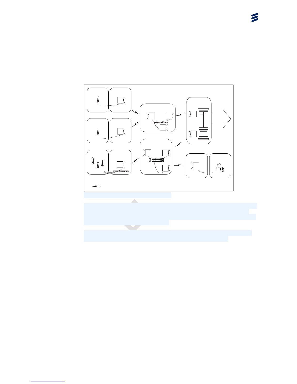
2 Scenarios
DC -48V 2A MAX
+ DC:2 - + DC:1 -
ERICSSON
MINI-LINK SP 110
Fault
Power
Oper
Sync
USB O&M O&MSYNC 2
USER I/OSYNC 1
1 1 2 3 4 TR:1A-1B TR:2A-2BTR:3A-3B TR:4A-4B3
2
10/100/1000 Base-T / 100/1000 Base-X
4
10/100/1000 Base-T
E1 / DS1
DC -48V 2A MAX
+ DC:2 - + DC:1 -
ERICSSON
MINI-LINK SP 110
Fault
Power
Oper
Sync
USB O&M O&MSYNC 2
USER I/OSYNC 1
1 1 2 3 4 TR:1A-1B TR:2A-2BTR:3A-3B TR:4A-4B3
2
10/100/1000 Base-T / 100/1000 Base-X
4
10/100/1000 Base-T
E1 / DS1
17258
PCU1
TRX
CBN
Air guide plate
FAU1
TN
FAU1
Cable shelf
Micro RBS
Microwave
Multiple RBSs
Multi standard
RBS6000/TCU
4G
3G
4G
2G
3G
2G
4G
Packet Terminal
Packet Terminal
Packet Terminal
Ericsson SP
MINI-LINK LH
Packet Terminal
Towards
HRAN/Metro
MINI-LINK TN
Packet Terminal
Packet Terminal
Ericsson SP
Enterprise
Packet Terminal
Figure 2 Network Scenario Overview
Using the MINI-LINK product portfolio to build an Ethernet network means that
there is a broad range of alternatives to choose from. There is support for
high-capacity Ethernet transport with different bandwidth and capacity options
over both radio and fixed connections.
The products offer the size and capacity to meet the needs of both last mile
access and first aggregation point, in a mobile backhaul network.
3
1/22102-HRA 901 17/9 Uen PU1 | 2016-07-04
Page 8

PRELIMINARY
Technical Description
4 1/22102-HRA 901 17/9 Uen PU1 | 2016-07-04
Page 9

PRELIMINARY
Radio Link Functions
3 Radio Link Functions
The packet radio operates within the 59–62 GHz frequency range, using 4, 16,
32, 64, 128, or 256 QAM, also supporting Adaptive Coding and Modulation
(ACM).
3.1
Adaptive Coding and Modulation
Adaptive Coding and Modulation (ACM) enables automatic hitless switching
between different ACM profiles, depending on radio channel conditions. Hitless
ACM makes it possible to increase the available capacity over the same
frequency channel during periods of normal propagation conditions.
Code rate and modulation (and thereby capacity) are high during normal radio
channel conditions and lower during less favorable channel conditions, for
example, when affected by rain or snow. ACM profile switches are hitless, that
is, error free. In situations where traffic interruption normally would occur, it is
possible to maintain parts of the traffic by switching to a lower ACM profile,
using hitless ACM.
Figure 3
shows how the capacity changes when the received input signal
crosses the receiver threshold for each ACM profile.
5
1/22102-HRA 901 17/9 Uen PU1 | 2016-07-04
Page 10

PRELIMINARY
Technical Description
Figure 3 Principles of Adaptive Coding and Modulation
When using only Adaptive Modulation, the steps in
Figure 3
only differ in
terms of modulation. When using ACM, the steps can differ in both coding and
modulation, which increases the number of possible steps.
In order to handle channel variations, the channel conditions are continuously
monitored on the Rx side by measurement of Signal to Noise and Interference
Ratio (SNIR). When the receiver, based on this data, detects that channel
conditions imply a change to the next higher or lower ACM profile, a message
is sent to the transmitter on the other side requesting a higher or lower ACM
profile. Upon receipt of such request the transmitter starts transmitting with the
new ACM profile. Each direction is independent. At demodulation the receiver
follows the ACM profile as a slave.
The ACM profile can also be configured with the maximum ACM profile equal to
the minimum ACM profile, and thereby achieving a mode comparable to static
mode, where the ACM profile remains unchanged.
Hitless ACM is compatible with Automatic Transmit Power Control (ATPC),
which is working in a closed loop only in the highest configured ACM profile. In
lower ACM profiles the output power is set as high as possible.
Note: Hitless ACM requires a license.
6
1/22102-HRA 901 17/9 Uen PU1 | 2016-07-04
Page 11

PRELIMINARY
Radio Link Functions
Buffering
ACM can influence the design of the buffer dimensioning. In case packet
aging is not used, the maximum delay variation time will increase due to that
the buffer is configured in bytes and that data will travel at a slower speed
during lower ACM profile steps. When packet aging is enabled, the maximum
delay variation time will be kept regardless of ACM profile level. This will also
ensure that there is no old data in lower priority queues when the ACM profile
is increased after a fading situation.
ACM can influence the position of the narrowest congestion point in the network,
with too small buffers this can have a strong negative impact on utilization
and end user TCP performance. To ensure high link utilization and high TCP
performance, buffers for TCP traffic should be dimensioned in the area above
average Round Trip Time (RTT), which is typically in the area of 100–200 ms.
3.2 Transmit Power Control
The radio transmit power can be controlled in Automatic Transmit Power
Control (ATPC) mode, including setting of associated parameters. In Automatic
Transmit Power Control (ATPC) mode the transmit power can be increased
rapidly during fading conditions and allows the transmitter to operate at less
than the maximum power during normal path conditions. The normally low
transmit power allows more efficient use of the available spectrum while the
high transmit power can be used as input to path reliability calculations, such
as fading margin and carrier-to-interference ratio.
The transmitter can be turned on or off from the management system.
P
out
P
Transmit power
min
P
max
16707
ATPC mode
Figure 4 Transmit Power Control
7
1/22102-HRA 901 17/9 Uen PU1 | 2016-07-04
Page 12

PRELIMINARY
Technical Description
ATPC is used to automatically adjust the transmit power P
out
in order to maintain
the received input level at the far-end radio at a target value. The received input
level is compared with the target value, a deviation is calculated and sent to the
near-end to be used as input for possible adjustment of the transmit power.
In ATPC mode, the transmit power P
out
varies between a selected maximum
level P
max
and a minimum level P
min
.
ECO mode is supported, and when ATPC mode is configured it is possible to
achieve a power consumption reduction with maintained performance.
3.3 Maximizing Radio Link Throughput
The maximum bit rate of incoming traffic on the LAN interface can be
significantly higher than the maximum bit rate over the radio link. For the radio
link to match the frame rate on the LAN interface, it is necessary to increase
the throughput on the radio link. This is done by stripping the IFG (interframe
gap) and preamble, and optionally by using multilayer header compression on
the Ethernet frames.
16782
Layer Preamble
Start of frame
delimit er
MAC
desti nation
MAC
source
802.1Q tag
(optional)
Ethert ype Payl oad
Frame chec k
sequence
IFG
Layer 2 Et hernet
frame
Layer 1 Et hernet
packet
Figure 5 Ethernet Packet and Frame Structure
Stripping the Preamble, SFD, and IFG
On the LAN side, the Layer 2 Ethernet data is encapsulated by a Layer 1
header consisting of an Preamble sequence, an SFD and an IFG. The IFG,
preamble and SFD are not needed in the traffic sent over the radio link. The
IFG and preamble are stripped from the packet, leaving only the Ethernet Layer
2 frame. A small overhead is added to the frame before it is sent over the
radio link. This way the traffic over the radio link consists almost entirely of the
payload, making it possible for the radio link to keep the same frame rate as
the LAN interface, even though the bit rate is lower.
8
1/22102-HRA 901 17/9 Uen PU1 | 2016-07-04
Page 13

PRELIMINARY
Radio Link Functions
Multi-Layer Header Compression
To further increase the frame rate over the radio link, Multi-Layer Header
Compression (MLHC) is used on the Ethernet frame. Fields in the header are
converted to a hash number, potentially resulting in a significant reduction in
the size of the frames sent over the radio link.
The MLHC algorithm inspects the header for Ethernet, IPv4, IPv6, UDP, MPLS
(up to three MPLS labels) and MPLS pseudowire information. See Table 1 for
examples of traffic throughput gain (in percent) for different frame types and
frame sizes when using MLHC:
Table 1 Traffic Throughput Gain for Different Frame Types when using MLHC
Frame Size (Bytes)
Frame Type
64 128 512
1500
Eth+S-tag+C
-tag
42% 18%
4% 1%
Eth+S-tag+C
-tag+IPv4+U
DP
143% 43%
8% 3%
Eth+S-tag+C
-tag+IPv6+U
DP
N/A
88%
13% 4%
Eth+ MPLS+I
Pv4
89% 32% 7% 2%
Eth+C-tag+S
-tag+3*MPLS
+L2 PW
278% 61% 10% 3%
Eth+C-tag+S
-tag+3*MPLS
+L3 PW
N/A
100% 14% 4%
3.4 Radio Link Compatibility
MINI-LINK 6351 is only hop compatible with another MINI-LINK 6351.
9
1/22102-HRA 901 17/9 Uen PU1 | 2016-07-04
Page 14

PRELIMINARY
Technical Description
10 1/22102-HRA 901 17/9 Uen PU1 | 2016-07-04
Page 15

PRELIMINARY
Ethernet Functions
4 Ethernet Functions
The packet radio is targeting multiple applications and network environments
with the embedded Ethernet capabilities. For information about the supported
Ethernet services, see Section 4.3 on page 13.
In addition to the Ethernet functions described in the following sections, the
following related functions are also available:
•
Synchronous Ethernet
, see
Section 5.2 on page
31.
• Ethernet Performance Counters
, see
Section 7.5.3 on page
43.
4.1
Ethernet in Microwave Networks
Compared to other transmission technologies, a microwave link can be
characterized as a limited bandwidth connection. This implies that microwave
equipment must be designed to enable maximum packet payload throughput
in the available bandwidth over the radio interface. The following features
improve the link efficiency:
Quality of Service
For connections with limited bandwidth it is important to prioritize high priority
packets when a connection is congested.
Adaptive Modulation
Adaptive modulation seeks continuously to use the modulation alternatives that
will maximize throughput under different conditions.
Low Residual BER
Microwave links operate with large fade margins and forward error correction
resulting in low residual BER level, typically 10
-12
.
Header Compression
The maximum bit rate of incoming traffic on the LAN interface can be
significantly higher than the maximum bit rate over the radio link. To maximize
the throughput on the radio link, parts of the Ethernet frame is removed and the
remaining headers are compressed before it is sent over the radio link.
11
1/22102-HRA 901 17/9 Uen PU1 | 2016-07-04
Page 16

PRELIMINARY
Technical Description
Ethernet WAN Buffer
The WAN port buffer has been designed to handle burst and congestion in
order to provide a high link utilization and goodput for high-speed data traffic.
Since extensive buffering has a negative impact on frame delay variation, it is
important to have the possibility to configure buffer/queue size for different
traffic classes independently.
This means that queues configured to handle delay variation sensitive traffic
such as synchronization traffic, shall be configured to be very short.
In contrast, for traffic queues for less delay variation sensitive traffic the
Transmission Control Protocol/Internet Protocol (TCP/IP) has a congestion
avoidance mechanism that is based on buffer utilization. In order to provide a
high link utilization and high TCP goodput, queues configured to handle this
type of traffic needs to be in the area of hundreds of milliseconds at the smallest
congestion point, equivalent to the network end-to-end Round-Trip time.
LAN port buffers are designed to be very small in order to keep delay variation
as small as possible, whereas WAN port buffers are larger, to enable handling
of congestion at the WAN port. Congestion at the WAN port can occur when
the WAN port link speed is lower than the LAN port link speed.
4.2 Ethernet Capacity
The ethernet capacity depends on the configuration of the NE.
Table 2 Ethernet Capacity
ACM Profile
CS (MHz) ACM
Layer 1 Line Capacity (Mbps)
64 QAM
1000
32 QAM
1000
16 QAM
981
250
4 QAM
490
128 QAM
1000
64 QAM
1000
32 QAM
980
16 QAM
784
200
4 QAM
391
12 1/22102-HRA 901 17/9 Uen PU1 | 2016-07-04
Page 17

PRELIMINARY
Ethernet Functions
ACM Profile
CS (MHz) ACM
Layer 1 Line Capacity (Mbps)
128 QAM
1000
64 QAM
869
32 QAM
724
16 QAM
579
150
4 QAM
289
256 QAM
770
128 QAM
673
64 QAM
578
32 QAM
481
16 QAM
385
100
4 QAM
191
256 QAM
382
128 QAM
334
64 QAM
286
32 QAM
238
16 QAM
190
50
4 QAM
95
4.3 Ethernet Services
Ethernet services according to MEF (Metro Ethernet Forum) specifications are
supported. Figure 6 shows a basic model for Ethernet services. The Ethernet
service is provided by Metro Ethernet Network (MEN) provider. The Customer
Edge (CE) and MEN exchange service frames across the User Network
Interface (UNI).
13
1/22102-HRA 901 17/9 Uen PU1 | 2016-07-04
Page 18

PRELIMINARY
Technical Description
Metro
Ethernet
Network
User network interface
UNI
User network
interface
UNI
Customer
Edge
Customer
Edge
12530
Figure 6 Ethernet Service Model
Based on Ethernet Virtual Connections (EVCs), the following service types
are supported:
• Point-to-Point EVC:
0
Ethernet Private Line (EPL) service
0
Ethernet Virtual Private Line (EVPL) service
•
Multipoint-to-Multipoint EVC:
0
Ethernet Private LAN (EPLAN) service
0
Ethernet Virtual Private LAN (EVPLAN) service
The LAN port can be used as a UNI, supporting up to 16 EVCs.
4.3.1 Ethernet Virtual Connection
An EVC is an instance of an association of two or more UNIs. It performs
two functions:
• Connects two or more customer sites (UNIs) enabling the transfer of
Ethernet service frames between them. The rules under which a service
frame is delivered to the destination UNI are specific to the particular
service definition.
• Prevents data transfer between customer sites that are not part of the
same EVC.
Two types of EVCs are supported:
•
Point-to-Point EVC (E-Line)
14
1/22102-HRA 901 17/9 Uen PU1 | 2016-07-04
Page 19

PRELIMINARY
Ethernet Functions
• Multipoint-to-Multipoint EVC (E-LAN)
Point-to-Point EVC (E-Line)
In a Point-to-Point EVC, also known as E-Line, exactly two UNIs are associated
with one another through the EVC. Service frames are transferred between
them. Figure 7 illustrates two Point-to-Point EVCs.
Metro
Ethernet
Network
EVC1
Customer
Edge
Customer
Edge
EVC2
Customer
Edge
12566
Figure 7 Point to Point EVC
Multipoint-to-Multipoint EVC (E-LAN)
In a Multipoint-to-Multipoint EVC, also known as E-LAN, two or more UNIs are
associated with one another through the EVC. It allows unicast, broadcast and
multicast service frames to be transferred from one ingress UNI to one or more
egress UNIs.
Figure 8 illustrates a Multipoint-to-Multipoint EVC.
Metro
Ethernet
Network
Customer
Edge
Customer
Edge
Customer
Edge
12567
Figure 8 Multipoint to Multipoint EVC
15
1/22102-HRA 901 17/9 Uen PU1 | 2016-07-04
Page 20

PRELIMINARY
Technical Description
4.3.2 Ethernet Private Line
The EPL is a type of Ethernet service based on a Point-to-Point EVC. It is
a point-to-point connection between the packet radio and a remote network
element, as shown in Figure 9. All Ethernet traffic ingress the UNI is mapped
into a single EVC and transported through the Metro Ethernet Network.
Metro
Ethernet
Network
Customer
Edge
Customer
Edge
12531
Figure 9 EPL
EPL is a port level service so there is no need for the customer and provider to
negotiate things like VLAN to be used. All ingress frames from one UNI will be
delivered to the other UNI without any modification to the packet. The following
functions are supported to implement EPL:
• Basic error checking of the Ethernet frames is performed (for example,
checking FCS, wrong Ethernet format, undersized packets or oversized
packets).
• Rate limiting is used to police the ingress Ethernet traffic from the
different subscribers to make it possible to meet the agreed Service Level
Agreements (SLA).
• Drop non-conforming traffic or remark them with lower priority.
• Priority is used to make it possible for high priority packets to bypass low
priority packets in buffers.
4.3.3 Ethernet Virtual Private Line
The EVPL is an Ethernet service similar to the EPL, but EVPL allows service
multiplexing at the UNI. This means that multiple EVCs can be accessed by the
subscriber from the UNI. Furthermore, the different EVCs one can access at a
particular UNI can be routed to different part of the network independently.
16
1/22102-HRA 901 17/9 Uen PU1 | 2016-07-04
Page 21

PRELIMINARY
Ethernet Functions
An example of EVPL is shown in Figure 10.
Metro
Ethernet
Network
Customer
Edge
Customer
Edge
12533
Figure 10 EVPL Service
It is possible to have multiple active EVPL services. The number is limited
to 16 EVCs per packet radio. The different Ethernet services can be routed
in different directions in the network.
Customer and service provider must agree on the mapping of different
C-VLANs into the different EVCs. The mapping of C-VLAN to EVC can be
one to one or many to one. Frames that arrive at the UNI with C-VLAN ID not
recognized by the service provider will be dropped at the UNI. The following
functions are supported to implement EVPL:
• Basic error checking of the Ethernet frames is performed (for example,
checking FCS, wrong Ethernet format, undersized packets or oversized
packets).
•
Rate limiting is used to police the ingress Ethernet traffic from the
different subscribers to make it possible to meet the agreed Service Level
Agreements (SLA).
• Drop non-conforming traffic or remark them with lower priority.
• Priority is used to make it possible for high priority packets to bypass low
priority packets in the buffers.
4.3.4 Ethernet Private LAN
An EPLAN provides LAN-type connectivity between multiple subscriber sites
through dedicated UNIs. An EPLAN service is shown in
Figure 11.
17
1/22102-HRA 901 17/9 Uen PU1 | 2016-07-04
Page 22

PRELIMINARY
Technical Description
14076
Met r o
Ethernet
Network
Custome r
Edge
Custome r
Edge
Figure 11 EPLAN
EPLAN is a port level service so there is no need for the customer and provider
to negotiate things like VLAN to be used. The mapping of C-VLAN to EVC can
be one to one or all to one. Frames that arrive at the UNI with C-VLAN ID
not recognized by the service provider are dropped at the UNI. The following
functions are supported to implement EVPL:
• Basic error checking of the Ethernet frames is performed (for example,
checking FCS, wrong Ethernet format, undersized packets or oversized
packets).
• Rate limiting is used to police the ingress Ethernet traffic from the
different subscribers to make it possible to meet the agreed Service Level
Agreements (SLA).
•
Drop non-conforming traffic or remark them with lower priority.
• Priority is used to make it possible for high priority packets to bypass low
priority packets in the buffers.
4.3.5 Ethernet Virtual Private LAN
The Ethernet Virtual Private LAN (EVPLAN) provides LAN-type connectivity
between multiple subscriber sites through multiplexed UNIs. With a multiplex
UNI, a particular customer site has access to multiple EVCs with that single
UNI. The different EVCs one can access at a particular UNI can be routed to
different parts of the network independently.
18
1/22102-HRA 901 17/9 Uen PU1 | 2016-07-04
Page 23

PRELIMINARY
Ethernet Functions
It is possible to have multiple active EVPLAN services. The number is limited
to 16 EVCs per packet radio. The different Ethernet services can be routed
in different directions in the network.
The following functions are supported to implement EVPLAN:
• Basic error checking of the Ethernet frames is performed (for example,
checking FCS, wrong Ethernet format, undersized packets or oversized
packets).
• Rate limiting is used to police the ingress Ethernet traffic from the
different subscribers to make it possible to meet the agreed Service Level
Agreements (SLA).
• Drop non-conforming traffic or remark them with lower priority.
•
Priority is used to make it possible for high priority packets to bypass low
priority packets in the buffers.
4.3.6 Maintenance Domains
A Maintenance Domain (MD) is defined as a network or sub-network, at the
Ethernet level, within which OAM frames are exchanged. An MD determines
the span of an OAM flow, across network administrative boundaries.
There are the following three types of MDs:
• Network Operator MD
• Service Provider MD
• Customer MD
MDs are hierarchal and as such, MDs of the same type do not overlap each
other, for example, two MDs of the same level do not overlap each other.
However, different MD types from different levels may overlap, for example, a
Customer MD may overlap multiple Service Provider MDs, but the Customer
MD cannot overlap another Customer MD.
An MD consists of the following components:
• Maintenance Entity (ME) — An OAM entity that requires management.
• Maintenance Domain (MD) — A management space on a network.
• Maintenance Association (MA) — A group of MEs that belong to the same
service inside a common MD.
• Maintenance End Point (MEP) — An OAM reference point that can initiate
and terminate OAM frames, and that reacts to diagnostic OAM frames.
19
1/22102-HRA 901 17/9 Uen PU1 | 2016-07-04
Page 24

PRELIMINARY
Technical Description
• Maintenance Intermediate Point (MIP) — An OAM reference point that
reacts to diagnostic OAM frames initiated by MEPs.
• MD Level — A way of distinguishing which MEs belong to the same MD. All
MEs belonging to the same MD share the same MD Level.
15527
Maintenance Association (MA)
Maintenance Domain (MD)
Network Element
Maintenance End Point (MEP)
Maintenance Intermediate Point (MIP)
MINI-LINK Other Network
Customer Customer
Figure 12 Ethernet Service OAM Network Overview
4.4 Quality of Service
Quality of Service (QoS) is a set of mechanisms that makes it possible to
prioritize Ethernet frames depending on traffic type, and to make sure that
the capacity is sufficient to guarantee a congestion-free network. QoS is an
alternative to overprovisioning the network.
A network is logically separated in an operator domain and one or more
customer domains, as in the example in Figure 13.
20
1/22102-HRA 901 17/9 Uen PU1 | 2016-07-04
Page 25

PRELIMINARY
Ethernet Functions
Customer
Domain
Customer
Domain
Operator Domain
Customer
Priority
Customer
Priority
Operator
Priority
Figure 13 Customer and Operator Domains
The priority of a frame in an end-to-end Ethernet connection can be different in
different parts of the network. Customers set the priority to use in their domains,
and the operator sets the priority to use in the operator domain.
Figure 14
shows an overview of the QoS mechanisms that the packet radio
supports. The following subsections describe the QoS mechanisms.
21
1/22102-HRA 901 17/9 Uen PU1 | 2016-07-04
Page 26

PRELIMINARY
Technical Description
Trusted
customer
priority
MPLS
DSCP
PCP
Classification
disabled or
no trusted
customer priority
Operator
priority
Shaping
buffer
Ethernet
egress
port
Priority queue 7
Priority queue 6
Priority queue 5
Priority queue 4
Priority queue 3
Priority queue 2
Priority queue 1
Priority queue 0
Frame
ingress
Mapping
tables
Default
priority
Frame
dropping
Frame
dropping
Mapping
table
Frame
dropping
Frame
egress
INGRESS
EGRESS
Classification Marking Policing
Queueing
• Tail dropping
• WRED
Switching
Queueing
• Aging
SchedulingMapping operator priority
to priority queue
Shaping
Figure 14 Overview of the QoS Mechanisms
In addition to the QoS mechanisms above, the packet radio also supports storm
protection, which provides protection against broadcast and multicast storms.
MINI-LINK 6351 supports multicast, unicast, and broadcast frames, and
supports frames with a size up to 9,216 bytes (Jumbo Frames).
22
1/22102-HRA 901 17/9 Uen PU1 | 2016-07-04
Page 27

PRELIMINARY
Ethernet Functions
MINI-LINK 6351 supports priority handling according to IEEE802.1Q 2005 and
IEEE802.1D 2004. In a network, it is important to only use one set of priority
definitions (for example, IEEE 802.1D 2004). Otherwise, the handling of traffic
types can differ between parts of the network in a non-predictable way.
4.4.1 Classification
The classification mechanism extracts customer priority in frames that enter
the operator domain.
The classification mechanism can extract the following types of customer
priority:
• MPLS TC value in the MPLS header
• IPv4 DSCP value in the IP header
• IPv6 DSCP value in the IP header
• PCP value in the C-tag or S-tag of the Ethernet header
The classification mechanism also supports the following types of combined
customer priority extraction:
• IPv4 and IPv6 headers
• MPLS headers, IP headers (both IPv4 and IPv6), and Ethernet headers,
in that priority order
4.4.2 Marking
The marking mechanism sets the operator priority.
If a frame contains trusted customer priority, the marking mechanism can use
the customer priority together with a mapping table to set the operator priority.
The marking mechanism sets the operator priority to the default priority in the
following cases:
•
the classification mechanism is disabled
• no trusted customer priority included in the frame
4.4.3 Policing
The policing mechanism makes sure that a customer does not use more than
the allowed resources in a network.
The policing mechanism limits the input bit rates based on a bandwidth profile.
The bandwidth profiles support the MEF concepts Committed Information
23
1/22102-HRA 901 17/9 Uen PU1 | 2016-07-04
Page 28

PRELIMINARY
Technical Description
Rate (CIR), Committed Burst Size (CBS), Excess Information Rate (EIR), and
Excess Burst Size (EBS). The policing mechanism drops excess traffic if the
bit rate reaches the configured maximum bit rate.
The policing mechanism supports bandwidth profiles for MEF services in one
of the following ways:
• Per UNI
•
Per UNI + CoS
• Per EVC
• Per EVC + CoS
4.4.4 Mapping Operator Priority to Priority Queue
The Ethernet egress port has eight priority queues (also known as Traffic
Classes (TCs)). The mechanism for mapping operator priority to priority queue
uses a mapping table to forward frames to the correct priority queue. To handle
temporary link congestion, the Ethernet egress port has a buffer. The priority
queues share the buffer capacity.
4.4.5 Queuing
The queuing mechanism supports the following queue management
mechanisms for the priority queues:
• Tail dropping
• Weighted Random Early Detection (WRED)
• Aging
A combination of queue management mechanisms is often used to get the
required behavior.
4.4.6
Scheduling
The scheduling mechanism handles congestion by emptying the priority queues
according to one or both of the following algorithms:
• Strict Priority (SP)
• Weighted Fair Queuing (WFQ)
The scheduling mechanism can be set up to work with one set of high-priority
SP queues, one set of WFQ queues, and optionally one low-priority SP queue,
as in the example in Figure 15.
24
1/22102-HRA 901 17/9 Uen PU1 | 2016-07-04
Page 29

PRELIMINARY
Ethernet Functions
Ethernet egress buffer
Priority queue 7
Priority queue 6
Priority queue 5
Priority queue 4
Priority queue 3
Priority queue 2
Priority queue 1
Priority queue 0
Empty first
Empty second
Empty third
Serve 40%
Serve 30%
Serve 20%
Serve 10%
Empty last
High-priority SP queues
WFQ queues
Low-priority SP queue
Figure 15 Example of Combined SP and WFQ Scheduling
The number of queues of each type is configurable (see
Table 3).
Table 3 Supported Combinations of SP and WFQ Priority Queues
Number of
high-priority SP
queues
Number of WFQ
queues
Number of low-priority
SP queues
8 0
0
0 8
0
2
6 0
3
5
0
3
4
1
4 3
1
4.4.7 Shaping
The shaping mechanism enforces a bit rate that is lower than the line rate of
the physical interface. The mechanism buffers excess frames and schedules
them for later transmission. Shaping results in a smoother frame output bit rate.
25
1/22102-HRA 901 17/9 Uen PU1 | 2016-07-04
Page 30

PRELIMINARY
Technical Description
4.4.8 Storm Protection
The storm protection mechanism protects other parts of the network from being
affected by flooding from broadcast or multicast traffic at a very high bit rate.
Storm protection can be activated per EVC to reduce unwanted or hostile
traffic. If the limit is reached, additional bits are discarded until the bit rate is
below the specified threshold.
The packet radio only supports storm protection on EVC, not on the port.
4.5 Ethernet Protection
4.5.1 Rapid Spanning Tree Protocol
The packet radio supports the Rapid Spanning Tree Protocol (RSTP) according
to the standard IEEE 802.1D (2004).
The RSTP mechanism adapts to changes in the physical network topology
(that is, links going down and coming up) faster than the traditional STP variant.
The STP variant takes a minute to adapt to a change, while the RSTP adapts
in less than a second.
4.6 Delay
Typical delay performance per link for priority traffic is <100 µs.
4.7 Ethernet Operation and Maintenance
This section describes O&M capabilities related to the Ethernet application.
4.7.1 Ethernet Link OAM
The packet radio supports the Ethernet link layer OAM based on the IEEE
802.3ah specification, which enables service providers to monitor and
troubleshoot a single Ethernet link. The primary benefits of IEEE 802.3ah are
that it enables the service provider to monitor a link for critical events and then,
if necessary, put the remote device into loopback mode in order to do a test on
the link.
The following IEEE 802.3ah features are supported:
• Discovery — Identifies devices in the network and their OAM capabilities.
It uses periodic OAM Protocol Data Units (PDUs) to advertise OAM mode,
configuration, and capabilities; to advertise PDU configuration; and platform
identity.
26
1/22102-HRA 901 17/9 Uen PU1 | 2016-07-04
Page 31

PRELIMINARY
Ethernet Functions
• Link Monitoring — Detects and indicates link faults under a variety of
conditions and uses the event notification OAM PDU to notify the remote
OAM device when it detects problems on the link.
• Remote Failure Indication — Notification of an Ethernet link failure to or
from far end for an NE in operation.
• Remote Loopback — Puts the remote link partner into loopback mode so
that every frame received is transmitted back on the same port. This is
used to ensure the quality of links during installation or troubleshooting.
4.7.2
Ethernet Service OAM
Ethernet Service OAM is used to manage networks comprising of multiple
LANs. It supports fault management on Ethernet links, according to IEEE
802.1Q 2011, and performance management according to ITU Y.1731.
Ethernet Service OAM can be used in both Customer mode and Provider
mode, if Ethernet Service OAM PDUs are C- or S-VLAN tagged, and can be
used in LAG and RSTP/MSTP scenarios.
15527
Maintenance Association (MA)
Maintenance Domain (MD)
Network Element
Maintenance End Point (MEP)
Maintenance Intermediate Point (MIP)
MINI-LINK Other Network
Customer Customer
Figure 16 Ethernet Service OAM Network Overview
27
1/22102-HRA 901 17/9 Uen PU1 | 2016-07-04
Page 32

PRELIMINARY
Technical Description
4.7.2.1 Ethernet Service OAM for Fault Management
The four main Ethernet Service OAM for FM functions are as follows:
• Continuity Check Monitoring — Continuity Check Monitoring detects
service interruption between MEPs. Continuity Check Messages (CCMs)
are sent from one MEP to another, enabling MEPs to locate other MEPs.
CCM confirmation can also be requested by an MEP from a linked MEP,
to ensure that the CCMs are sent and received without fault. The CCM
intervals can be set at 3.3 ms, 10 ms, 100 ms, 1 s, 10 s, 1 min, or 10 min.
• Remote Defect Indication
— An MEP uses Remote Defect Indication
(RDI) to communicate with linked MEPs that a fault has occurred, usually
that CCM confirmation were not received. The RDI is an indication that a
fault has occurred either at the far-end MEP or between the two MEPs.
• Loopback
— Loopback is a troubleshooting tool that verifies the
connectivity of a MEP with linked MEPs and linked Maintenance
Intermediate Points (MIPs).
• Linktrace
— Linktrace is a bidirectional continuity check used for fault
localization. When a Linktrace Message (LTM) is sent to a destination
MEP or MIP, a Linktrace Reply (LTR) is expected from all the intermediate
MIPs along the path to the destination and from the destination MEP or
MIP itself. Missing or misordered LTRs point out the location of a fault in
an efficient way.
4.7.2.2 Ethernet Service OAM for Performance Management
Performance management as defined by ITU Y.1731 is supported.
The ITU Y.1731 standard specifies the following features:
• Throughput is a measurement on the basis of the Loop Back Message
(LBM) and Loop Back Response (LBR) messages. The throughput is
measured by sending frames at an increasing rate (up to the theoretical
maximum), graphing the percentage of received frames, and reporting the
rate at which frames start being dropped. In general, this rate is dependent
on the frame size.
Up to 90 Mbps of throughput testing traffic can be generated.
• Delay Measurement (DM) can be used for on-demand OAM to measure
frame delay and frame delay variation. Frame delay and frame delay
variation measurements are performed by sending periodic frames with
DM information to the peer Maintenance End Point (MEP), and receiving
frames with DM information from the peer MEP during the diagnostic
interval. Each MEP can perform frame delay and frame delay variation
measurement. When a MEP is enabled to generate frames with DM
information, it periodically sends frames with DM information to its peer
MEP in the same ME. When a MEP is enabled to generate frames with DM
28
1/22102-HRA 901 17/9 Uen PU1 | 2016-07-04
Page 33

PRELIMINARY
Ethernet Functions
information, it also expects to receive frames with DM information from its
peer MEP in the same ME.
A MEP sends frames with DM request information to its peer MEP, and
receives frames with DM reply information from its peer MEP to perform
two-way frame delay and two-way frame delay variation measurements.
The Protocol Data Unit (PDU) used for DM request is Delay Measurement
Message (DMM). The PDU used for DM reply is Delay Measurement
Response (DMR).
•
Single-Ended Loss Measurement (LM), including Loss Measurement
Message (LMM) and Loss Measurement Response (LMR), is used to
collect counter values applicable to ingress and egress service frames,
where the counters maintain a count of transmitted and received data
frames between a pair of MEPs. single-ended LM is used for on-demand
OAM. In this case, a MEP sends frames with LM request information to its
peer MEP and receives frames with LM reply information from its peer
MEP to perform loss measurement.
Note: LM can be performed in two ways: single-ended LM and
dual-ended LM. The radio only supports single-ended LM.
The radio supports storing a large amount of Performance Measurement (PM)
data, including the following:
• Delay and delay variation measurements:
0
Average, maximum and minimum measured round trip delay of the
interval
0
Average, maximum and minimum measured round trip Inter Frame
Delay Variation (IFDV)
• Frame loss measurements:
0
Average measured in one way frame loss ratio forward direction
0
Total frames sent and received in forward direction
0
Average measured in one way frame loss ratio reverse direction
0
Total frames sent and received in reverse direction
29
1/22102-HRA 901 17/9 Uen PU1 | 2016-07-04
Page 34

PRELIMINARY
Technical Description
30 1/22102-HRA 901 17/9 Uen PU1 | 2016-07-04
Page 35

PRELIMINARY
Synchronization Functions
5 Synchronization Functions
By default, the packet radio works in Free Running mode. In this mode, the
packet radio is not a part of the synchronization network, and does not maintain
a SEC.
The packet radio can also be configured to work in Network Synchronized mode
where it maintains a SEC and distributes synchronization and synchronization
quality level status according to ITU-T G.8261, G.8262, and G.8264.
5.1
Network Synchronized Mode
Network Synchronized mode makes it possible to build a synchronized network
where all the NEs are synchronized to the same source.
Figure 17
shows an
example of a network where the synchronization information is carried to all the
NEs through an assigned path. In case of link failures, the synchronization can
be reestablished using the unassigned synchronization paths.
Active synchronization path
Inactive synchronization path
9531
NE
NE
NE
NE
NE
NE
Figure 17 Master-Slave Synchronized Network
In this mode, the packet radio uses the Node Clock on all the protocol layers
generated in the node.
31
1/22102-HRA 901 17/9 Uen PU1 | 2016-07-04
Page 36

PRELIMINARY
Technical Description
5.2 Network Synchronization Methods
The packet radio supports the following methods for network synchronization:
• Synchronization over radio link
• Synchronous Ethernet (SyncE) according to the ITU-T G.8261, G.8262,
and G.8264 standards.
• Transparent Clock (TC) according to the IEEE 1588-2008 standard.
It is possible to configure one or more of the above methods. If more methods
are used, a general rule is to configure the packet radios on either side of a hop
so that one uses Ethernet and the other uses radio link as sync source. If TC is
used, it is recommended to enable SyncE.
32
1/22102-HRA 901 17/9 Uen PU1 | 2016-07-04
Page 37

PRELIMINARY
Hardware
6 Hardware
The packet radio is an antenna sphere painted light gray, with a wall mount
and arm painted dark gray.
17252
MINI-LINK 6351
Figure 18 Mechanical Design
The horizontal deflection angle (how much the antenna can be turned sideways)
depends on the vertical deflection angle (how much the antenna is turned up
or down).
Vertical deflection angle Maximum horizontal deflection
angle
0
±80
±65
±68
331/22102-HRA 901 17/9 Uen PU1 | 2016-07-04
Page 38

PRELIMINARY
Technical Description
External Interfaces
SDD5130901_1_P1C
17255
3
4
2
1
Figure 19 External Interfaces, Mechanical Design
Item
Description
1
Operation & Maintenance socket for local O&M cable.
2
Test port for antenna alignment.
3
Slot for RMM.
4
Socket for PoE cable.
The packet radio is environmentally sealed, so that it can withstand most
conditions. The antenna, O&M cover, and PoE connection are sealed.
34
1/22102-HRA 901 17/9 Uen PU1 | 2016-07-04
Page 39

PRELIMINARY
Management
7 Management
7.1 DCN
The packet radio supports L2 DCN, and needs to be configured as a host on a
LAN with an IP address, a subnet mask, and a default gateway.
The packet radio provides DCN over VLAN for transport of the O&M data.
Figure 20
illustrates the DCN configuration.
Radio TerminalLAN
Packet Radio
Internal DCN
VLAN Switch
CPU
Figure 20 DCN over VLAN
The DCN is carried in-band on the traffic cable or the Radio Link on a separate
VLAN. This VLAN is terminated in the packet radio.
The remote supervision of the packet radio can be realized with a connection
over the line side or the Radio Link in-band DCN management VLAN.
7.1.1 IP Services
The following standard external IP network services are supported:
• All clocks, used for example, for time stamping alarms and events,
can be synchronized with a Network Time Protocol (NTP) server. NTP
authentication is supported.
• Secure File Transfer Protocol (SFTP) is used as a file transfer mechanism
for software upgrade.
• An embedded Node GUI, including an overview of the and status
information.
35
1/22102-HRA 901 17/9 Uen PU1 | 2016-07-04
Page 40

PRELIMINARY
Technical Description
NTP
SFTP
DCN
CLI
Site LAN
Packet Radio
Ethernet Switch
Figure 21 IP Services
7.2 Management Tools and Interfaces
The packet radio provides two management tools:
• Command Line Interface (CLI)
• Node GUI
The management tools can connect to the packet radio using one of the
following management interfaces:
• a DCN for local and remote access (see
Section 7.1 on page
35)
• an Ethernet management interface (not connected to the router) for local
access
36
1/22102-HRA 901 17/9 Uen PU1 | 2016-07-04
Page 41

PRELIMINARY
Management
ServiceOn
Element Manager
DCN
Packet Radio
CLI
Site LAN
CLI
Ericsson IP Transport NMS
Local Port
Ethernet Switch
Figure 22 Management Tools and Interfaces
The CLI and the Node GUI can be used, for example, for the following
management tasks:
• configuration management
• fault management
• performance management
• software management
The configuration management features of the Node GUI are limited compared
to configuration management features of the CLI.
7.2.1 CLI
A CLI provides commands for on-site installation, configuration management,
fault management, performance management, and software upgrade. It is also
used to configure the traffic routing function, protection and DCN.
The CLI is used for local management, that is the
packet radio is accessed
locally, on the unit, by connecting a PC to the Ethernet Management Port,
with a cable.
37
1/22102-HRA 901 17/9 Uen PU1 | 2016-07-04
Page 42

PRELIMINARY
Technical Description
This CLI is similar to Cisco’s industry standard router configuration and is
accessed from a Command Prompt window using SSH.
The
packet radio can also be accessed over the site LAN. In this case, a VLAN
capable Ethernet switch has to be used, and the port where the PC is connected
should be configured to be on the same VLAN as set up for the in-band DCN.
7.2.2 Node GUI
The
packet radio has a built-in GUI that provides tools for on-site installation
and software upgrade.
The Node GUI is used for local management, that is the
packet radio is
accessed locally, on the unit, by connecting a PC to the Ethernet Management
Port, with a cable.
The
packet radio can also be accessed over the site LAN. In this case, a VLAN
capable Ethernet switch has to be used, and the port where the PC is connected
should be configured to be on the same VLAN as set up for the in-band DCN.
7.2.3 ServiceOn Element Manager
The packet radio is managed remotely using ServiceOn Element Manager.
ServiceOn Element Manager provides functions such as FM, CM, AM, PM and
SM based on the recommendations from Open Systems Interconnect (OSI)
model. The CM functionality is either embedded or provided using dedicated
Local Managers and Element Managers. ServiceOn Element Manager can also
be used to mediate FM, PM and Inventory data to other management systems.
The system provides:
• Fault Management
• Configuration Management
• Performance Management
• Security Management
• Remote Software Upgrade
ServiceOn Element Manager provides element management services across
a whole network. Network elements can be managed on an individual basis,
providing the operator with remote access to several network elements, one
by one.
ServiceOn Element Manager supports a real time window reporting alarms and
events from the managed network elements. It is possible to filter alarms on the
basis of assigned resources and alarm filtering criteria.
38
1/22102-HRA 901 17/9 Uen PU1 | 2016-07-04
Page 43

PRELIMINARY
Management
7.2.4 Ericsson IP Transport Network Management System
The Ericsson IP Transport Network Management System (IPT NMS) provides
full management across a whole network through one easy to use browser. IPT
NMS manages end-to-end L1, L2, and L3 services across TDM, Ethernet, and
IP, IPT NMS also manages all standard Ethernet services.
IPT NMS is compatible with existing NMS hardware and operating systems,
and easily integrates third-party network equipment.
7.2.5 SNMP
The
packet radio has support for Simple Network Management Protocol
(SNMP) versions SNMPv1, SNMPv2c, and SNMPv3.
This SNMP support enables integration with any SNMP-based network
management system (NMS). The SNMP interface of the
packet radio uses
standard MIBs and enterprise MIBs.
The
packet radio supports fetching the following types of information:
• General NE information data:
0
Basic
0
Environmental
0
Inventory
• Alarm and event data:
0
Historical alarms and events
• Performance data:
0
Performance counter values
• Configuration data:
0
Radio link data
Notifications from the packet radio are sent using SNMP v1, SNMP v2c, and
SNMP v3 traps.
7.2.6 MINI-LINK Configuration Generator
MINI-LINK Configuration Generator (CG) is an offline tool for simplifying the
Network Rollout (NRO) process. MINI-LINK CG uses radio link planning data
and transport planning data as input to create configuration scripts for NEs,
see Figure 23.
39
1/22102-HRA 901 17/9 Uen PU1 | 2016-07-04
Page 44

PRELIMINARY
Technical Description
MINI-LINK CG is compatible with MINI-LINK 6351 2.4 and later.
MINI-LINK CG can combine radio link planning data and transport planning
data to generate one common CLI configuration script. This enables an
installation technician to configure each NE by deploying the script, rather than
by performing configurations step-by-step in a graphical user interface.
MINI-LINK CG takes Network Configuration Files (NCFs) as input and
generates CLI scripts for the NE included in the NCF. An NCF is an XML
document that is compliant with a certain XML schema, called the NCF
schema. MINI-LINK CG can also combine planning data in the NCF format with
templates, and then merge and convert the NCFs to create deployable CLI
configuration scripts for selected sites and NEs.
MINI-LINK CG provides offline validation to reduce configuration errors and
does not need connect to the NE to create the configuration scripts
The configuration scripts generated by MINI-LINK CG can be deployed to
separate NEs through SOEM, through a CLI session, or by placing them on the
RMMs in the packet radio (see
Section 7.3.3 on page
41).
Integrate and create
CLI Scripts
MINI-LINK Configuration Generator (CG)
Microwave Planning
Transport Planning
MINI-LINK
MINI-LINK
Network/site
engineer
Integration
engineer
CLI Script Distribution
NCF Interface (XML)
File-based Network
Rollout
Installation
technician
Network
operator
Planning and Export
15804
Figure 23 MINI-LINK CG Overview
For further information about MINI-LINK CG, see MINI-LINK CG documentation.
40
1/22102-HRA 901 17/9 Uen PU1 | 2016-07-04
Page 45

PRELIMINARY
Management
7.3 Configuration Management
Configuration management operations are performed using CLI or an
XML-based protocol towards a ServiceOn Element Manager (SOEM).
7.3.1 Configuration File
The configuration file is stored both in the RMM and in a flash memory on
the
packet radio.
If a
packet radio needs to be replaced, the RMM from the faulty
packet radio
can be inserted in the new
packet radio.
If a packet radio or an RMM is replaced, the configuration file identity of the
RMM and flash memory are compared on power up. If the configuration file
identity differs, the configuration file on the RMM is used.
7.3.2 Automatic Rollback
An automatic rollback function for the configuration is available. When this
function is enabled, most changes to the configuration are temporary (to avoid
malfunction, changes that has to do with the internal configuration database,
licenses, software, and users are always saved).
Unless a command to save the changes is entered within 15 minutes, the
configuration automatically reverts to the state it was in before the changes
were made,
7.3.3 Scripts on RMM
CLI scripts that are located on the RMM are executed automatically when the
packet radio is powered up.
MINI-LINK RMM Writer is needed to write scripts to the RMM. MINI-LINK RMM
Writer is part of MINI-LINK Configuration Generator.
7.4 Fault Management
All software and hardware in operation is monitored by the control system. The
control system locates and maps faults to replaceable HW parts.
The practical fault management is based around alarm and event notifications.
Reporting of some alarms is turned off by default. Furthermore, alarm filter
persistency is set for some types of alarms by default. This may prevent
reporting of some types of alarms by default.
41
1/22102-HRA 901 17/9 Uen PU1 | 2016-07-04
Page 46

PRELIMINARY
Technical Description
Alarm notifications can be enabled or disabled for the entire system (terminal).
Disabling alarm notifications means that no new alarm or event notifications
are sent to the management system.
For a list of replaceable HW parts, see Section 7.6 on page 44.
Fault management for Ethernet is described in Section 4.7 on page 26.
7.5 Performance Management
7.5.1 General
The purpose of Performance Management for the
packet radio is to monitor the
performance of
the Ethernet interface and the RF interface.
Performance data is stored in a volatile memory, so that a restart will lose
all gathered data.
7.5.2 Radio Link Performance Counters
The following table shows the performance counters that are monitored:
Table 4 Performance Counters, their Respective Counting Intervals, and the Type of Data
Stored in the NE
Performance counter
Counting Intervals
Data stored in the NE
RF input power 15 minutes intervals The counters for the current
15 minutes and the previous
96×15 minutes
RF output power 15 minutes intervals The counters for the current
15 minutes and the previous
96×15 minutes
42 1/22102-HRA 901 17/9 Uen PU1 | 2016-07-04
Page 47

PRELIMINARY
Management
Table 4 Performance Counters, their Respective Counting Intervals, and the Type of Data
Stored in the NE
Performance counter
Counting Intervals
Data stored in the NE
Adaptive Modulation states 15 minutes (default) or 24
hours intervals
The seconds spent in each
modulation as well as the
number of changes between
modulations are counted
G.826
The following performance
counters are used by G.826:
• Errored Seconds (ES)
• Severely Errored Seconds
(SES)
•
Background Block Error
(BBE) (only structured
interfaces)
• Unavailable Seconds (UAS)
• Elapsed time
• Background Block
Continuous (default), 15
minutes, or 24 hours intervals
•
Continuous data
• The current 15 minutes and
the previous 96×15 minutes
• The current 24 hours and
the previous 30×24 hours
7.5.3 Ethernet Performance Counters
The following Ethernet performance counters are available:
Bandwidth Utilization — Measures bandwidth utilization per port or per Traffic
Class on the WAN port.
• Average, Max, and Min bandwidth
• Bandwidth utilization histogram
Queuing Delay
— Measures queuing delay per port or per Traffic Class on
the WAN port.
• Average, Max, and Min delay
• Delay histogram
RMON — Performance counters as specified in IETF RFC 2819.
• Separate counters for LAN and WAN ports
• RMON counter statistics are sampled every 900 seconds (15 minutes)
and stored in 96 intervals.
43
1/22102-HRA 901 17/9 Uen PU1 | 2016-07-04
Page 48

PRELIMINARY
Technical Description
IfStatistics Counters — Performance counters as specified in IETF RFC 1213.
• Separate counters for LAN and WAN ports
• IfStatistics counters are continuous counters
7.6 Hardware Management
The
packet radio is a single HW unit
, including both a modem part and a radio
part.
The replaceable parts of a
packet radio system are:
• The
packet radio unit
• RMM
When replacing an optical SFP, no configuration is needed.
RMMs containing new licenses can be replaced, no new configuration is
needed.
When replacing a
packet radio, the new
packet radio must be configured
according to the set up requirements. The previous RMM or a new RMM must
be inserted as they are not included with the package.
7.7 Software Management
The packet radio software is upgraded using a load module, which is
downloaded from a server and stored in the flash memory.
7.8 License Management
The packet radio has a mini-SIM card reader on the board for the RMM. The
RMM contains licenses and can be accessed in the RJ45 O&M Adapter.
Optional features can be expanded by installing license keys that enable
additional optional features. Licenses for optional features are distributed in a
License Key File (LKF), which can be stored on the RMM.
Features for the
packet radio are only enabled if a corresponding license is
available on the inserted RMM.
To upgrade the licenses on the
packet radio, new licenses can be downloaded
remotely.
The license key installation can be made both locally and remotely, without
disturbing the traffic through the
packet radio. License keys can also be
preinstalled at delivery, when a complete and preconfigured
packet radio
is purchased.
44
1/22102-HRA 901 17/9 Uen PU1 | 2016-07-04
Page 49

PRELIMINARY
Management
For more information about license management, see License System.
7.9 Security Management
All management access to the NE is protected by a user name and a password.
The following user roles are defined:
• guest with read-only access
• operator with read and write access
• net-admin with read and write access
• sys-admin with read and write access
Note: Only the sys-admin has full read and write access. The operator and
net-admin have full read access, but limited write access.
All users have an associated password. All users can change their own
passwords, but only users with the sys-admin user role can change passwords
for other users.
Secure Shell (SSH) protocol can be used for secure remote access and use of
CLI commands.
The
packet radio offers two types of authentication towards the external SSH
server: passwords or the Rivest-Shamir-Adleman (RSA) key algorithm. The
RSA algorithm uses a public and a private key for authentication and makes
it possible to log on without a password. The key pair is generated on the
SSH server with a maximum size of 1024 bits. The public key is placed on the
SSH server, while the private key is installed on the
packet radio. After the
installation of the private key, the NE is able to log on to the external SSH
server without a password. Another advantage of using RSA keys is that it
provides protection for the external SSH server against brute-force attacks, as
the keys used are too long to crack them.
AAA
Authentication, Authorization, and Accounting (AAA) is a security architecture
for distributed systems. The Authentication process makes sure that only
accepted users can log on to the system, for example, using user names
and passwords. The Authorization process gives authenticated users certain
permissions, for example, based user roles. The Accounting process records
information about access and use of the system.
There are three AAA policies in MINI-LINK: local, RADIUS, and TACACS+.
Note: If the connection to the remote AAA server is interrupted, the NE falls
back to local authentication.
45
1/22102-HRA 901 17/9 Uen PU1 | 2016-07-04
Page 50

PRELIMINARY
Technical Description
Local
The local policy supports the following features:
• Authentication
For local user authentication, it is necessary to supply authentication
information in the form of a username and password. During the
authentication process, the NE searches its locally stored configuration
for a user with a matching username. If a matching username cannot be
found, the request is refused. The maximum number of local users the
packet radio supports is sixteen.
• Authorization
The NE uses local authorization information to distinguish which privileges
belong to a role.
The authorization process is based on the user role (system admin,
network admin, operator, or guest). For local user authentication, the role is
defined when the user account is created, and is stored locally as part of
the user configuration.
RADIUS
The RADIUS protocol, which is based on a client-server model, enables remote
access to networks and network services. When configured with the IP or host
name of a RADIUS server, the NE can act as a RADIUS client. The format
and validation of RADIUS packets is in accordance with the IETF protocol
specification RFC 2865. The NE does not support RADIUS accounting features.
RADIUS uses UDP, which offers best-effort delivery.
RADIUS only encrypts the password in the Access-Request packet from the
client to the server. The rest of the packet (for example, username, authorized
services, and accounting) is not encrypted.
RADIUS supports the following features:
• Authentication
The NE supports both local user authentication and remote authentication
using RADIUS. A user needs to have an account created on the external
server before logging on. Once the account is created, it can be
configured to receive either local authentication or remote authentication
using RADIUS. For local user authentication, it is necessary to supply
authentication information in the form of a username and password. During
the authentication process, the NE searches its locally stored configuration
for a user with a matching username. If a matching username cannot be
found, the request is refused. The maximum number of local users the NE
supports is sixteen.
46
1/22102-HRA 901 17/9 Uen PU1 | 2016-07-04
Page 51

PRELIMINARY
Management
• Authorization
The NE supports fetching the user roles through a RADIUS server. The
NE uses local authorization information to distinguish which privileges
belong to a role.
The authorization process is based on the user role (system admin,
network admin, operator, or guest). For local user authentication, the
role is defined when the user account is created, and is stored locally
as part of the user configuration. For authentication using RADIUS,
the RADIUS server provides the user role when the user logs on to
the NE . For locally-authenticated users, the locally stored user policy
configuration will be used, for example, password expiration and user
account expiration. The NE can be managed in situations when a
RADIUS server is unreachable. Therefore it ensures there is always
at least one locally-authenticated system administrator account. The
default locally-authenticated system administrator account is
admin.
The NE does not allow any configuration change that would delete all
locally-authenticated system administrator accounts.
• RADIUS Server-Client Feature
The NE supports up to six RADIUS servers. It connects to the servers
one-by-one according to their priorities. If no server is reachable, the NE
enables local authentication automatically.
The NE supports three RADIUS packet types: Access-Request,
Access-Accept, and Access-Reject.
A RADIUS Access-Request message containing the authentication
information is sent to a remote server. When the RADIUS server receives
the request, it validates the client using a “shared secret”. If the client
is valid, the RADIUS server consults its user database to validate the
access. The server responds to an Access-Request message with either
an Access-Reject message or an Access-Accept message. On receipt
of an Access-Reject message, the client refuses access to the user. On
receipt of an Access-Accept message, the client grants access to the user.
If the NE does not receive a RADIUS response to an Access-Request
message within the configured timeout, it keeps retransmitting the request
until it receives a response, or until the configured number of maximum
transmissions has been reached.
TACACS+
The TACACS+ protocol enables the building of a system that secures remote
access to networks and network services. TACACS+ is based on a client/server
architecture. The TACACS+ servers are configured on a per-context basis, with
a limit of six servers.
47
1/22102-HRA 901 17/9 Uen PU1 | 2016-07-04
Page 52

PRELIMINARY
Technical Description
TACACS+ uses the Authentication, Authorization, and Accounting (AAA)
architecture. This allows separate authentication solutions that can still use
TACACS+ for authorization and accounting.
TACACS+ uses TCP, which offers connection-oriented transport.
TACACS+ encrypts the entire body of the packet, but leaves a standard
TACACS+ header. Within the header is a field that indicates whether the body
is encrypted or not. For debugging purposes, it is useful to have the body of
the packets unencrypted. However, during normal operation, the body of the
packet is fully encrypted for securer communications.
TACACS+ supports the following features:
• Authentication
The NE supports both local user authentication and remote authentication
using TACACS+. A user needs to have an account created on the
external server before logging on. Once the account is created, it can be
configured to receive either local authentication or remote authentication
using TACACS+. For local user authentication, it is necessary to supply
authentication information in the form of a username and password. During
the authentication process, the NE searches its locally stored configuration
for a user with a matching username. If a matching username cannot be
found, the request will be refused. The maximum number of local users
the NE supports is sixteen.
• Authorization
The NE supports fetching the user roles through a TACACS+ server, and
the NE uses local authorization information to distinguish which role has
what kinds of privileges.
The authorization process is based on the user role (system admin,
network admin, operator, or guest). For local user authentication, the
role is defined when the user account is created, and is stored locally
as part of the user configuration. For authentication using TACACS+,
the TACACS+ server provides the user role when the user logs on to
the NE. For locally-authenticated users, the locally stored user policy
configuration will be used, for example, password expiration and user
account expiration. The NE can be managed in situations when a
TACACS+ server is unreachable. Therefore it ensures there is always
at least one locally-authenticated system administrator account. The
default locally-authenticated system administrator account is admin. The
NE does not allow any change in configuration which would result in no
locally-authenticated system administrator accounts.
48
1/22102-HRA 901 17/9 Uen PU1 | 2016-07-04
Page 53

PRELIMINARY
Management
SFTP
An SFTP server can be used to upgrade NE system software, instead of just
using an FTP server. Using SFTP instead of FTP ensures that the entire
session, including passwords, is encrypted.
Firewall
A firewall is in place for packet filtering on the IP address and the range of the IP
address. The packet filter option is protection from external traffic connections
through each possible port or service by closing or opening commands.
Security Protocols
To increase the security, it is possible for the operator to block a security
protocol if a certain service is not needed, or to redirect a protocol to another
port. The following security protocols are configurable:
• SSH - SSH server
• HTTP - Web server
• HTTPS - Web server Secure Socket Layer (SSL) connection
• SNMP - SNMP server
• XRPC - XML based Remote Procedure Calls (XRPC) server
SSL/TLS Certificates
The NE has a built-in web server that hosts the Node GUI as a web server
application that is accessed using a web browser. By default, a web browser
communicates with the web server over HTTPS using a default self-signed
SSL/TLS certificate that is not unique for the NE.
If the default certificate is not approved by the organizations security policy, it
can be replaced with one of the following types of certificates:
• A node-unique certificate that is signed by a trusted certificate provider.
• A node-unique self-signed certificate that is generated by the NE.
NTP Authentication
To prevent manipulation of the time signal, the
packet radio authenticates the
NTP server it is connected to. An alarm is generated if the connection to the
NTP server is lost.
The user is able to do the following:
• Enable/disable authentication
49
1/22102-HRA 901 17/9 Uen PU1 | 2016-07-04
Page 54

PRELIMINARY
Technical Description
• Download a keyfile from an external server. The keyfile contains a number
of cryptographic NTP keys.
50
1/22102-HRA 901 17/9 Uen PU1 | 2016-07-04
Page 55

PRELIMINARY
Accessories
8 Accessories
The packet radio product program contains a number of accessories for
installation and operation. This section gives additional technical information
for some accessories.
8.1 Power Over Ethernet
One electrical Ethernet cable can supply the packet radio with Ethernet
payload, in-band DCN, and DC-power when using the Power Over Ethernet
(PoE) accessories.
The equipment used for PoE support is the following:
• PoE injector, for either AC or DC power supply
• Pole mounting kit (optional)
• PoE cable
Figure 24 PoE Overview
8.1.1 PoE Injector
The PoE injector merges the Ethernet payload and the input power on to the
wires in the electrical Ethernet cable. It also provides overvoltage protection
towards the indoor parts, the power supply, and the Ethernet interface. The
PoE injector supports one packet radio and can be mounted on a wall or in a
mast using an optional pole mounting kit.
51
1/22102-HRA 901 17/9 Uen PU1 | 2016-07-04
Page 56

PRELIMINARY
Technical Description
The Ethernet and PoE cables are connected to the injector using shielded
RJ45 connectors.
There are two versions of the injector: one for AC power supply and one for
DC power supply.
Power supply requirements for the AC version:
Input Voltage: 100 to 240 V AC
Input Current:
1A
Frequency:
50 to 60 Hz
Power supply requirements for the DC version:
Input Voltage:
30 to 60 V DC
Input Current:
1A
8.1.2 Power Over Ethernet Cable
One Ethernet cable can supply the packet radio with Ethernet payload, in-band
DCN, and DC-power. The cable has an angled, environmentally sealed, RJ45
connector on the end that is connected to the packet radio, and a standard
RJ45 on the other.
17254
Figure 25 Power over Ethernet Cable
52
1/22102-HRA 901 17/9 Uen PU1 | 2016-07-04
Page 57

PRELIMINARY
Accessories
8.2 Alignment Camera
The alignment camera attaches to the MINI-LINK 6351 and streams the camera
image over Wi-Fi to a smartphone running the MINI-LINK Alignment app,
simplifying alignment.
16635
Figure 26 Alignment Camera
8.3 Commissioning Guide
Commissioning Guide can run on a PC or on a mobile device (such as a mobile
phone or tablet) that is connected to the packet radio. Commissioning Guide
requires a web browser that supports HTML 5.
It is possible to use Commissioning Guide for the following tasks during
installation:
• Antenna alignment
• Installation verification
53
1/22102-HRA 901 17/9 Uen PU1 | 2016-07-04
Page 58

PRELIMINARY
Technical Description
54 1/22102-HRA 901 17/9 Uen PU1 | 2016-07-04
Page 59

PRELIMINARY
Technical Specifications
9 Technical Specifications
This section summarizes some technical specifications for the packet radio.
9.1 Power Supply Requirements
The packet radio is power supplied with
Power over Ethernet.
Table 5 PoE Power Supply
Power Supply
Nominal
Minimum
Maximum
PoE+ PD Type 2
+53 V DC
+42.5 V DC
+57 V DC
Proprietary PoE
-48 V DC
-39.5 V DC
-58.8 V DC
9.2 Power Consumption
The typical power consumption for one
packet radio, excluding power cable
loss, is
< 25.5 W.
9.3 Dimensions and Weight
The following dimensions and weight apply for the packet radio:
• Weight:
2.4 kg
• Sphere diameter: 175 mm
55
1/22102-HRA 901 17/9 Uen PU1 | 2016-07-04
Page 60

PRELIMINARY
Technical Description
56 1/22102-HRA 901 17/9 Uen PU1 | 2016-07-04
Page 61

PRELIMINARY
Federal Communications Commission and Industry Canada Notices
10 Federal Communications Commission and
Industry Canada Notices
This device complies with Part 15 of the FCC Rules and with Industry Canada
licence-exempt RSS standard(s). Operation is subject to the following two
conditions: (1) this device may not cause harmful interference, and (2) this
device must accept any interference received, including interference that may
cause undesired operation.
Le présent appareil est conforme aux CNR d'Industrie Canada applicables
aux appareils radio exempts de licence. L'exploitation est autorisée aux deux
conditions suivantes: (1) l'appareil ne doit pas produire de brouillage, et (2)
l'utilisateur de l'appareil doit accepter tout brouillage radioélectrique subi, même
si le brouillage est susceptible d'en compromettre le fonctionnement.
This equipment has been tested and found to comply with the limits for a
Class B digital device, pursuant to Part 15 of the FCC Rules. These limits
are designed to provide reasonable protection against harmful interference
in a residential installation. This equipment generates, uses and can radiate
radio frequency energy and, if not installed and used in accordance with
the instructions, may cause harmful interference to radio communications.
However, there is no guarantee that interference will not occur in a particular
installation. If this equipment does cause harmful interference to radio or
television reception, which can be determined by turning the equipment off and
on, the user is encouraged to try to correct the interference by one or more of
the following measures:
• Reorient or relocate the receiving antenna.
• Increase the separation between the equipment and receiver.
• Connect the equipment into an outlet on a circuit different from that to which
the receiver is connected.
• Consult the dealer or an experienced radio/TV technician for help.
Changes or modifications made to this equipment not expressly approved by
(manufacturer name) may void the FCC authorization to operate this equipment.
57
1/22102-HRA 901 17/9 Uen PU1 | 2016-07-04
 Loading...