

Page 1

LBI-38976
Mobile Communications
MDX
DESK TOP STATION
Operator's Manual
Page 2

TABLE OF CONTENTS
Page
INTRODUCTION ............................................................... 3
OPERATION OF THE STANDARD STATION
WITHOUT OPTIONS ........................................... 5
STATION WITH REMOTE OPTION ................................. 5
OPERATION OF THE STATION WITH
REMOTE OPTION ............................................... 5
KEYPAD/FREQUENCY SELECT BOARD OPTION ......... 8
KEYPAD OPERATION
To Make An Individual Call From The Keypad ..... 8
To Make A Telephone Interconnect
Call From The Keypad ............................ 9
EDACS REMOTE OPERATION ........................................ 10
TABLE - REMOTE & INTERCOM AUDIO
INTERFACE SUMMARY .................................... 11
ILLUSTRATIONS
Figure 1 - Base Station Controls And Indicator ..... 3
Figure 2 - Control Panel With Single
LED Power Indicator ............................... 4
Figure 3 - Control Panel With Remote Option ....... 4
Figure 4 - Control Panel With Keypad Option ....... 9
Figure 5 - Control Panel With Remote
and Keypad Options ................................. 10
Copyright September 1993, Ericsson GE Mobile Communications Inc.
2
WARRANTY
A. Ericsson GE Mobile Communications Inc. (hereinafter "Seller") warrants to the original purchaser for use
(hereinafter "Buyer") that Equipment manufactured by Seller shall be free from defects in material, workmanship and
title, and shall conform to its published specifications. With respect to any Equipment not manufactured by Seller
(except for integral parts of Seller's Equipment to which the warranties set forth above shall apply). Seller gives no
warranty, and only the warranty, if any, given by the manufacturer shall apply. Batteries are excluded from this warranty
but are warranted under a separate Nickel-Cadmium Battery Warranty.
B. Seller's obligations set forth in Paragraph C below shall apply only to failures to meet the above warranties (except
as to title) occurring within the following periods of time from date of sale to the Buyer and are conditioned on Buyer's
giving written notice to Seller within thirty (30) days of such occurrence:
1. for fuses, incandescent lamps, vacuum tubes and non-rechargeable batteries, operable on arrival only.
2. for parts and accessories (except as noted in B.1) sold by Seller's Service Parts Operation, ninety (90) days.
3. for all other Equipment of Seller's manufacture, one (1) year.
C. If any Equipment fails to meet the foregoing warranties, Seller shall correct the failure at its option (i) by repairing
any defective or damaged part or parts thereof, or (ii) by making available at Seller's factory any necessary repaired or
replacement parts. Any repaired or replacement part furnished hereunder shall be warranted for the remainder of the
warranty period of the Equipment in which it is installed. Where such failure cannot be corrected by Seller's reasonable
efforts, the parties will negotiate an equitable adjustment in price. Labor to perform warranty service wil l be provided at
no change only for the Equipment covered under Paragraph B.3, and only during the first three (3) months following the
date of sale to the Buyer. Thereafter, labor will be charged at prevailing rates. To be eligible for no-charge labor, service
must be performed by an authorized General Electric Service Station or other Servicer approved for these purposes
either at its place of business during normal business hours, for mobile or personal equipment, or at the Buyer's
location, for fixed location equipment. Service on fixed location equipment more than thirty (30) miles from the Service
Station or other approved Servicer's place of business will include a charge for transportation. Equipment located off-
shore is not eligible for no-charge labor.
D. Seller's obligations under Paragraph C shall not apply to any Equipment, or part thereof, which (i) has been
modified or otherwise altered other than pursuant to Seller's written instructions or written approval or, (ii) is normally
consumed in operation or, (iii) has a normal life inherently shorter than the warranty periods specified in Paragraph B, or
(iv) is not properly stored, installed, used, maintained or repaired, or, (v) has been subjected to any other kind of misuse
or detrimental exposure, or has been involved in an accident.
E. The preceding paragraphs set forth the exclusive remedies for claims (except as to title) based upon defects in or
nonconformity of the Equipment, whether the claim is in contract, warranty, tort (including negligence), strict liability or
otherwise, and however instituted. Upon the expiration of the warranty period, all such liability shall terminate. The
foregoing warranties are exclusive and in lieu of all other warranties, whether oral, written, expressed, implied or
statutory. NO IMPLIED OR STATUTORY WARRANTIES OF MERCHANTABILITY OR FITNESS FOR PARTICULAR
PURPOSE SHALL APPLY. IN NO EVENT SHALL THE SELLER BE LIABLE FOR ANY INCIDENTAL,
CONSEQUENTIAL, SPECIAL, INDIRECT OR EXEMPLARY DAMAGES.
This warranty applies only within the United States.
ECX-362R
6/90 Printed in U.S.A.
Page 3
INTRODUCTION
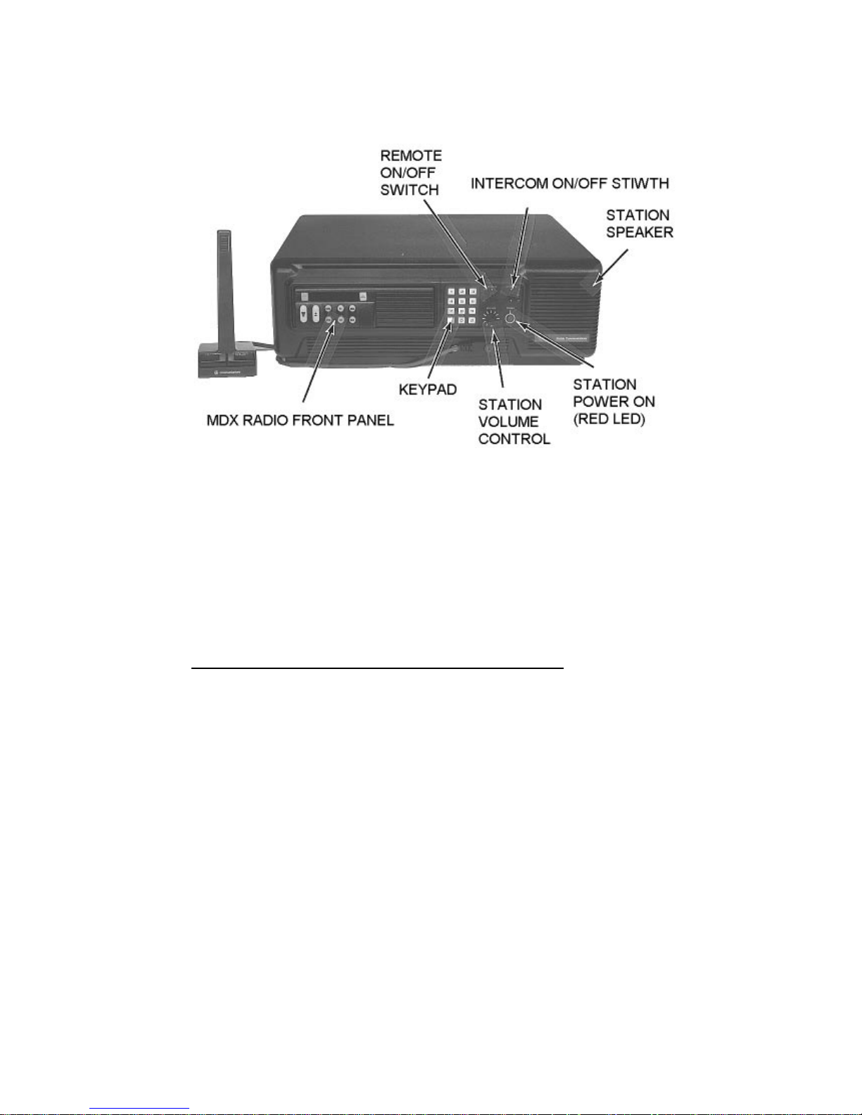
Figure 1 - Base Station Controls and Indicators
The front panel of the Ericsson GE Desk Top Station, as shown in
Figure 1, includes the front of an MDX conventional/ EDACS™
radio, as well as a Control Panel. The Station is assembled as a
standard Station with or without one of the combinations of options.
The control panel is illustrated for each combination:
•• Standard
Desk Top Station, Without Options - The standard
Station has only a single RED LED to indicate when the power
supply is ON (see Figure 2).
The power supply ON/OFF switch is mounted on the rear of the
Station housing.
3
Page 4
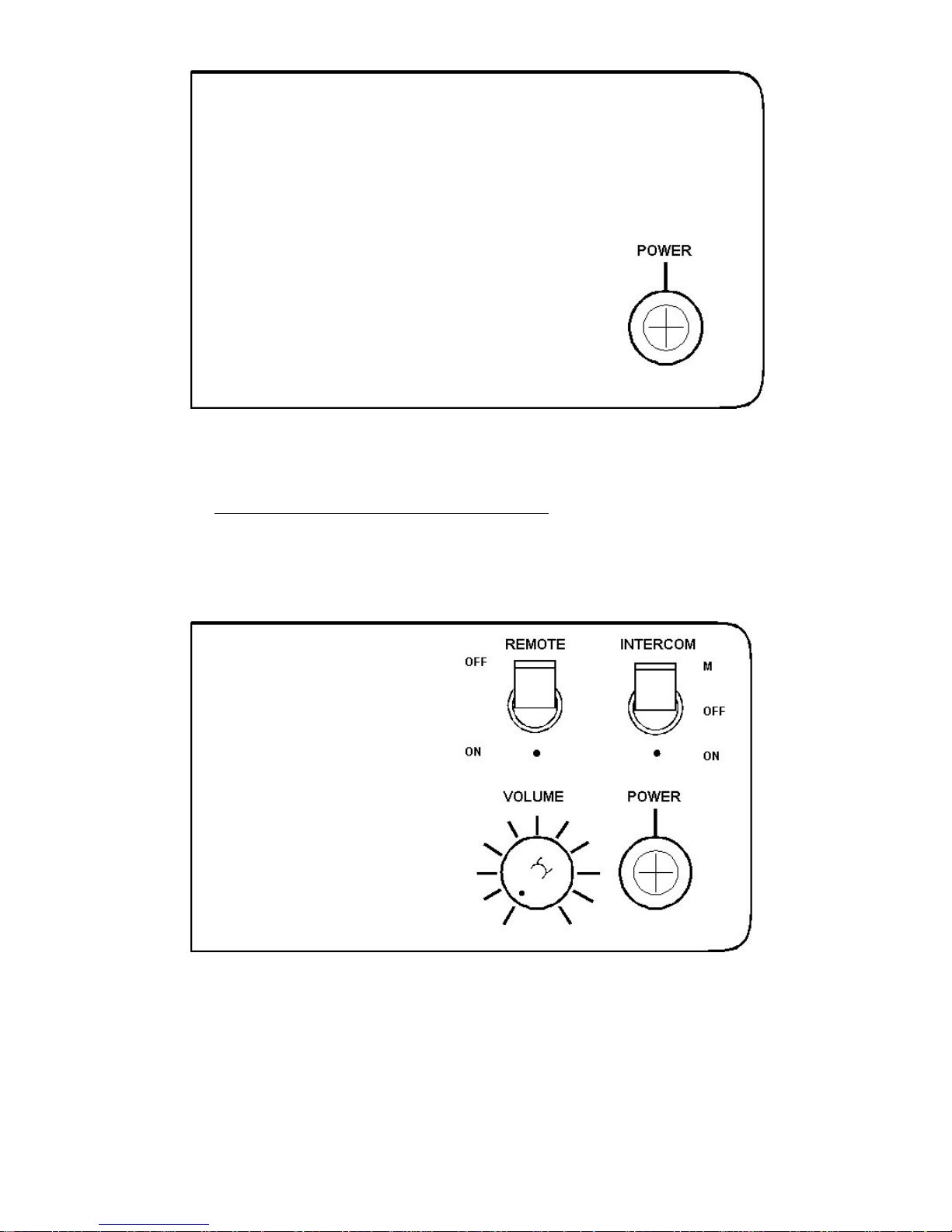
Figure 2 - Control Panel With Single LED Power Indicator
••
Standard Station with Remote Option - In addition to the LED
POWER indicator, there is a REMOTE ON/OFF switch, an
INTERCOM ON/OFF/Momentary switch and a VOLUME
control (see Figure 3).
Figure 3 - Control Panel With Remote Option
4
Page 5

OPERATION OF THE STANDARD STATION
WITHOUT OPTIONS
Operation of the Standard Station without any option begins with
turning ON the POWER switch. The POWER switch is located on
the rear of the power supply, accessible at the rear of the Desk Top
Station housing. The POWER indicator lights, showing that the
power supply is ON. The radio is not ON yet. The Power Supply
provides power to the Station cooling fan. The fan operation is
temperature controlled. Internal cabinet temperature determines when
the fan runs. The radio has its own ON/OFF POWER Switch.
The radio uses the Station Speaker mounted behind the front cap of
the Station. The radio's internal speaker is not used. The radio must be
programmed for a variable volume control.
Further operation of the Station is that of the MDX radio. Refer to the
applicable Operator's Manual for more detailed information.
STATION WITH REMOTE OPTION
The DC/Tone Remote Options permit use of ERICSSON GE's RCN1000 Remote Control Consoles with the Desk Top Station. Any of
these options require that the Station have a DC or Tone Remote
Board with a Remote Interface Board. These options provide for a two
or four wire interface to the consoles for these functions:
• Transmit, Receive and Intercom Audio
• Transmit Keying (PTT) Control
• Channel Guard Monitor
OPERATION OF THE STATION WITH REMOTE
OPTION
Operation of the Desk Top Station is described for four combinations
of the INTERCOM switch and the REMOTE switch positions. These
two switches control the various audio paths between remote and local
microphones, the radio, and remote and local speakers.
5
Page 6

1. Desk Top Intercom Switch ON, Remote Switch ON
With this switch arrangement, intercom communication is
possible between the Desk Top Station and the Remote Console.
Also, the Remote Console can key the radio transmitter and hear
the receiver's audio output.
When the Desk Mic PTT is keyed, there is no connection to the
radio transmitter. If the radio receiver is squelched, the speaker at
the Remote Console hears the audio as an intercom conversation.
Should the radio receiver be unsquelched, receiver audio is heard
on both the Desk Top speaker and the Remote Console speaker,
with priority over the intercom message from the Desk Mic to the
Remote speaker.
The audio from the microphone at the Remote Console is heard
on the Desk Top Station speaker. The Remote Console's
INTERCOM switch must be OFF to key the station's radio
transmitter.
The audio from the unsquelched radio receiver is heard on both
the Station speaker and the Remote Console speaker.
Intercom messages from the Remote Consoles are muted when
radio messages are being received, or when the Desk Top Station
operator is using the Desk Mic PTT.
2. Desk Top Intercom Switch ON, Remote Switch OFF
This arrangement offers intercom service only. Neither the Desk
Top Station nor the Remote Console microphone can be used to
key the radio transmitter. The radio receiver's audio can be heard
on the Station speaker, but not on the Remote Console speaker.
A message from the Desk Mic is heard on the Remote speaker.
An intercom message from the Remote Mic can be heard on the
Station speaker, but only if the Desk Mic is not
active. The Desk
Mic has priority over the Remote Console microphone in the
intercom connection.
6
Desk Top Intercom Switch ON, Remote Switch ON
Remote Mic>Radio Xmtr
Remote Mic>Station Spkr
Desk Mic
/>Radio Xmtr
Desk Mic
>Remote Spkr, If Rx is muted,
otherwise Rx>Remote Spkr and
Station Spkr
Rx Audio
>Station Spkr & Remote Spkr
Desk Top Intercom Switch ON, Remote Switch OFF
Remote Mic/
>Radio Xmtr
Remote Mic>Station Spkr, if Desk Mic PTT inactive
Desk Mic
/>Radio Xmtr
Desk Mic
>Remote Spkr
Rx Audio
/>Remote Spkr
Rx Audio
>Station Spkr
Desk Top Intercom Switch OFF, Remote Switch ON
Remote Mic>Radio Xmtr, if no Desk Mic; otherwise
with Desk Mic PTT, Desk
Mic >Radio Xmtr
Remote Mic>Desk Spkr, if Desk Mic PTT inactive,
otherwise Remote Mic muted
Desk Mic
>Radio Xmtr with Desk Mic PTT
Desk Mic
>Remote Spkr
Rx Audio
>Remote Spkr, if Rx unmuted
Rx PA Audio
>Station Spkr
Desk Top Intercom Switch OFF, Remote Switch OFF
Remote Mic/
>Radio Xmtr
Remote Mic/
>Station Spkr
Desk Mic
>Radio Xmtr
Desk Mic
/>Remote Spkr
Rx Audio
/>Remote Spkr
Rx PA Audio
>Station Spkr
Key: Connection = >
No Connection = />
Page 7

3. Desk Top Intercom Switch OFF, Remote Switch ON
These switch settings are for remote control of the radio, without
an intercom connection.
When the Desk Mic is keyed, the radio transmitter is keyed and
the Remote Console is able to monitor the transmission.
The Remote Console microphone is connected to the radio
transmitter if the Remote Console Mic is keyed and the Desk Mic
is not keyed. Also, the Remote Console Mic is connected to t he
Station speaker if the radio receiver is squelched and the Desk
Mic is not keyed (so that the "Desk Mic Audio to Line Path" is
inactive).
The radio receiver audio is connected to the Remote Console
speaker if the receiver is unsquelched. The P.A. output from the
receiver is unconditionally connected to the Station speaker, but is
subject to the radio's internal squelch.
4. Desk Top Intercom Switch OFF, Remote Switch OFF
This arrangement is for operating the Desk Top Station as a radio.
The Desk Mic is connected only to the radio transmitter, when the
Desk Mic is keyed.
The radio receiver's P.A. audio output is connected only to the
Station speaker.
A summary of the audio path connections for the four combinations of
INTERCOM and REMOTE Switches is given in the Table Remote
and Intercom Audio Interface Summary.
The VOLUME Control is a rotary potentiometer on the Desk Top
Station Control Panel which controls the level of the audio signal fed
to the Station speaker as determined by the choice of INTERCOM
and REMOTE switch positions.
The volume control on the mobile must be variable for the local
control station only.
7
Page 8

With the MDX remote radio, the rotary VOLUME control adjusts
both the receiver and the intercom audio levels. The radio volume
control buttons are disabled by a PC programming option so that the
receiver audio volume level is fixed and the internally adjusted
"Intercom Level" adjusts the intercom audio relative to the receiver
audio. This arrangement allows all Alert Tones generated by the radio
to pass to the Remote Consoles at a suitable level independent of the
Desk Top Station rotary VOLUME control. Refer to applicable
Operator's Manual for specific information on setting the audio level
of the particular radio installed.
KEYPAD/FREQUENCY SELECT BOARD OPTION
The Keypad Option is compatible with the MDX radio (see Figures 4
& 5). When the desktop station is equipped with the Keypad/Remote
board, the unit is capable of placing individual calls to other mobiles
on the system as well as making interconnect calls. The board also
allows operation with a five (5) function remote RC-1000 controller
when tone remote control board 19A704686P8 is installed in the
station.
KEYPAD OPERATION
To Make An Individual Call From The Keypad
1. Push the MENU button on the radio to select the special call
mode
2. Enter the unit ID of the radio to be called using the keypad. The
allowed range is from 1 to 16382 (this range may be restricted by
the PC programmer).
3. Key the desk microphone to call the individual unit. The radio
will transmit and receive only to the individual radio in this mode
and no other units in the fleet can hear the call. The individual
unit ID will be displayed on the radio as long as the call is in
progress.
4. Push either the CLR button on the radio or the pound (#) key on
the keypad to end the call and return to normal operation.
8
To Make A Telephone Interconnect Call From The Keypad:
1. Push the MENU button on the radio to select the special call
mode.
2. Enter the desired phone number using the keypad.
3. Push the star (*) key on the keypad and wait for the radio to dial
the number.
4. Key the desk microphone PTT switch to talk and release it to
listen.
5. Push either the CLR button on the radio or the pound (#) key on
the keypad to end the call and return to normal operation.
Page 9

To Make A Telephone Interconnect Call From The Keypad:
1. Push the MENU button on the radio to select the special call
mode.
2. Enter the desired phone number using the keypad.
3. Push the star (*) key on the keypad and wait for the radio to dial
the number.
4. Key the desk microphone PTT switch to talk and release it to
listen.
5. Push either the CLR button on the radio or the pound (#) key on
the keypad to end the call and return to normal operation.
Figure 4 - Control Panel with Remote Options and Keypad
9
Page 10

Figure 5 - Control Panel With Remote and Keypad Options
EDACS REMOTE OPERATION
The RCN-1000 Remote Controller is capable of selecting up to five (5)
predefined radio system/group/special call combinations. The presets
are programmed into the radio by the PC Programmer.
The remotes and desktop station can operate as an intercom by setting
the INTERCOM switch to ON or M.
Remotes can be disabled by setting the station REMOTE switch to
OFF.
To Place A Call From The Remote:
1. Select the desired SF function switch on the RCN-1000. The
LED next to the function switch will illuminate.
2. Key the microphone PTT switch and wait for a short beep
before beginning to speak. Release the PTT when you're
finished.
3. Adjust the volume as needed while receiving a call.
10
3. Desk Top Intercom Switch OFF, Remote Switch ON
These switch settings are for remote control of the radio, without
an intercom connection.
When the Desk Mic is keyed, the radio transmitter is keyed and
the Remote Console is able to monitor the transmission.
The Remote Console microphone is connected to the radio
transmitter if the Remote Console Mic is keyed and the Desk Mic
is not keyed. Also, the Remote Console Mic is connected to t he
Station speaker if the radio receiver is squelched and the Desk
Mic is not keyed (so that the "Desk Mic Audio to Line Path" is
inactive).
The radio receiver audio is connected to the Remote Console
speaker if the receiver is unsquelched. The P.A. output from the
receiver is unconditionally connected to the Station speaker, but is
subject to the radio's internal squelch.
4. Desk Top Intercom Switch OFF, Remote Switch OFF
This arrangement is for operating the Desk Top Station as a radio.
The Desk Mic is connected only to the radio transmitter, when the
Desk Mic is keyed.
The radio receiver's P.A. audio output is connected only to the
Station speaker.
A summary of the audio path connections for the four combinations of
INTERCOM and REMOTE Switches is given in the Table Remote
and Intercom Audio Interface Summary.
The VOLUME Control is a rotary potentiometer on the Desk Top
Station Control Panel which controls the level of the audio signal fed
to the Station speaker as determined by the choice of INTERCOM
and REMOTE switch positions.
The volume control on the mobile must be variable for the local
control station only.
Page 11

TABLE - REMOTE & INTERCOM AUDIO
INTERFACE SUMMARY
Desk Top Intercom Switch ON, Remote Switch ON
Remote Mic
>Radio Xmtr
Remote Mic
>Station Spkr
Desk Mic />Radio Xmtr
Desk Mic
>Remote Spkr, If Rx is muted,
otherwise Rx
>Remote Spkr and
Station Spkr
Rx Audio
>Station Spkr & Remote Spkr
Desk Top Intercom Switch ON, Remote Switch OFF
Remote Mic/>Radio Xmtr
Remote Mic
>Station Spkr, if Desk Mic PTT inactive
Desk Mic />Radio Xmtr
Desk Mic
>Remote Spkr
Rx Audio />Remote Spkr
Rx Audio
>Station Spkr
Desk Top Intercom Switch OFF, Remote Switch ON
Remote Mic
>Radio Xmtr, if no Desk Mic; otherwise
with Desk Mic PTT, Desk
Mic
>Radio Xmtr
Remote Mic
>Desk Spkr, if Desk Mic PTT inactive,
otherwise Remote Mic muted
Desk Mic
>Radio Xmtr with Desk Mic PTT
Desk Mic
>Remote Spkr
Rx Audio
>Remote Spkr, if Rx unmuted
Rx PA Audio >Station Spkr
Desk Top Intercom Switch OFF, Remote Switch OFF
Remote Mic/>Radio Xmtr
Remote Mic/>Station Spkr
Desk Mic
>Radio Xmtr
Desk Mic />Remote Spkr
Rx Audio />Remote Spkr
Rx PA Audio >Station Spkr
Key: Connection =
>
No Connection = />
11
Page 12

NOTES
12
OPERATION OF THE STANDARD STATION
WITHOUT OPTIONS
Operation of the Standard Station without any option begins with
turning ON the POWER switch. The POWER switch is located on
the rear of the power supply, accessible at the rear of the Desk Top
Station housing. The POWER indicator lights, showing that the
power supply is ON. The radio is not ON yet. The Power Supply
provides power to the Station cooling fan. The fan operation is
temperature controlled. Internal cabinet temperature determines when
the fan runs. The radio has its own ON/OFF POWER Switch.
The radio uses the Station Speaker mounted behind the front cap of
the Station. The radio's internal speaker is not used. The radio must be
programmed for a variable volume control.
Further operation of the Station is that of the MDX radio. Refer to the
applicable Operator's Manual for more detailed information.
STATION WITH REMOTE OPTION
The DC/Tone Remote Options permit use of ERICSSON GE's RCN-
1000 Remote Control Consoles with the Desk Top Station. Any of
these options require that the Station have a DC or Tone Remote
Board with a Remote Interface Board. These options provide for a two
or four wire interface to the consoles for these functions:
• Transmit, Receive and Intercom Audio
• Transmit Keying (PTT) Control
• Channel Guard Monitor
OPERATION OF THE STATION WITH REMOTE
OPTION
Operation of the Desk Top Station is described for four combinations
of the INTERCOM switch and the REMOTE switch positions. These
two switches control the various audio paths between remote and local
microphones, the radio, and remote and local speakers.
Page 13

NOTES
13
Page 14

NOTES
14
The front panel of the Ericsson GE Desk Top Station, as shown in
Figure 1, includes the front of an MDX conventional/ EDACS™
radio, as well as a Control Panel. The Station is assembled as a
standard Station with or without one of the combinations of options.
The control panel is illustrated for each combination:
•• Standard
Station has only a single RED LED to indicate when the power
supply is ON (see Figure 2).
The power supply ON/OFF switch is mounted on the rear of the
Station housing.
Page 15

WARRANTY
A. Ericsson GE Mobile Communications Inc. (hereinafter "Seller") warrants to the original purchaser for use
(hereinafter "Buyer") that Equipment manufactured by Seller shall be free from defects in material, workmanship and
title, and shall conform to its published specifications. With respect to any Equipment not manufactured by Seller
(except for integral parts of Seller's Equipment to which the warranties set forth above shall apply). Seller gives no
warranty, and only the warranty, if any, given by the manufacturer shall apply. Batteries are excluded from this warranty
but are warranted under a separate Nickel-Cadmium Battery Warranty.
B. Seller's obligations set forth in Paragraph C below shall apply only to failures to meet the above warranties (except
as to title) occurring within the following periods of time from date of sale to the Buyer and are conditioned on Buyer's
giving written notice to Seller within thirty (30) days of such occurrence:
1. for fuses, incandescent lamps, vacuum tubes and non-rechargeable batteries, operable on arrival only.
2. for parts and accessories (except as noted in B.1) sold by Seller's Service Parts Operation, ninety (90) days.
3. for all other Equipment of Seller's manufacture, one (1) year.
C. If any Equipment fails to meet the foregoing warranties, Seller shall correct the failure at its option (i) by repairing
any defective or damaged part or parts thereof, or (ii) by making available at Seller's factory any necessary repaired or
replacement parts. Any repaired or replacement part furnished hereunder shall be warranted for the remainder of the
warranty period of the Equipment in which it is installed. Where such failure cannot be corrected by Seller's reasonable
efforts, the parties will negotiate an equitable adjustment in price. Labor to perform warranty service wil l be provided at
no change only for the Equipment covered under Paragraph B.3, and only during the first three (3) months following the
date of sale to the Buyer. Thereafter, labor will be charged at prevailing rates. To be eligible for no-charge labor, service
must be performed by an authorized General Electric Service Station or other Servicer approved for these purposes
either at its place of business during normal business hours, for mobile or personal equipment, or at the Buyer's
location, for fixed location equipment. Service on fixed location equipment more than thirty (30) miles from the Service
Station or other approved Servicer's place of business will include a charge for transportation. Equipment located off-
shore is not eligible for no-charge labor.
D. Seller's obligations under Paragraph C shall not apply to any Equipment, or part thereof, which (i) has been
modified or otherwise altered other than pursuant to Seller's written instructions or written approval or, (ii) is normally
consumed in operation or, (iii) has a normal life inherently shorter than the warranty periods specified in Paragraph B, or
(iv) is not properly stored, installed, used, maintained or repaired, or, (v) has been subjected to any other kind of misuse
or detrimental exposure, or has been involved in an accident.
E. The preceding paragraphs set forth the exclusive remedies for claims (except as to title) based upon defects in or
nonconformity of the Equipment, whether the claim is in contract, warranty, tort (including negligence), strict liability or
otherwise, and however instituted. Upon the expiration of the warranty period, all such liability shall terminate. The
foregoing warranties are exclusive and in lieu of all other warranties, whether oral, written, expressed, implied or
statutory. NO IMPLIED OR STATUTORY WARRANTIES OF MERCHANTABILITY OR FITNESS FOR PARTICULAR
PURPOSE SHALL APPLY. IN NO EVENT SHALL THE SELLER BE LIABLE FOR ANY INCIDENTAL,
CONSEQUENTIAL, SPECIAL, INDIRECT OR EXEMPLARY DAMAGES.
This warranty applies only within the United States.
ECX-362R
6/90 Printed in U.S.A.
15
Page 16

Printed in U.S.A.
 Loading...