

Ericsson MASTR II 4EF4A1, MASTR II 4EF4A2, MASTR II 4EF4A3 Maintenance Manual
Mobile Communications
MASTR® II
POWER AMPLIFIER
MODELS 4EF4A1,2,3
Maintenance Manual
LBI-4938C
Printed in U.S.A.
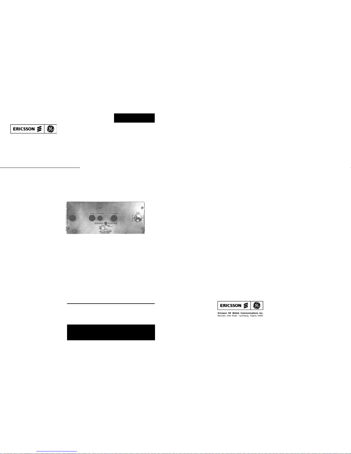
DESCRIPTION
General Electric Power Amplifier Models 4EF4A1, 2
and 3 operate in the 25-54 megahertz band. They are used
with an external driver and power supply to provide a power
output between 150 and 300 watts. The amplifier employs a
4CX250B as a power amplifier tube, with forced-air cooling
providedby a blower mounted on the power supply. Standard
RETMA rack-mounting dimensions are used. The tuning
controls most frequently used are located on the front of the
unit.
All the power connections, except the high voltage connection, are made with a 6-pin plug from the front of the
unit. High voltage is brought to the plate at the rear of the
plate compartment.
Antenna relay keying voltage connections are made behind the output Power Indicator, using screw connections.
The RF drive connection is made by an RG-58/U cable
plugged into the driver from the front of the unit.
CIRCUIT A NALYSIS
Excitation of the Power Amplifier at P482 is fed to coupling loop L482 and coupled to coil L484, which, with
C481, forms the grid tank of the amplifier. By adjusting the
PA GRID control (C481), the grid tank may be tuned to the
operating frequency. Coil L481 isolates RF from the power
cable.
In order to obtain optimum tube life the filament voltage
on the Power Amplifier tube V481 is set at the factory for 6
Volts with R4 on the High Power Power Supply. The filament voltage can be set for a higher value but with a corresponding decrease in tube life. C482, C483, and C484 are
RF by-pass capacitors and R481 is used as a screen RF decoupling resistor. Built into the tube socket, XV481, is a
ring-type capacitor which is used as a screen grid by-pass.
All input voltage connections to the Power Amplifier , except the B-plus voltage connection, are made at P481 on the
front side of the panel. The 2000-volt B-plus lead is connected at terminal P0-2 located in the rear on the plate cavity
cover. C485 provides bypassing for the B-plus and L485 is
an RF choke. The plate tank is composed of C488 and
L494. The plate tank is tuned to the operating frequency by
adjusting the PA PLA TE control C488.
Adjusting the PA COUPLING control varies the coupling from the plate to the output by controlling the amount
of magnetic flux linking the plate coupling loop to the outputloop. The filter consists of L490, L491, L492, L493,
C492, C493, L494 and C495.
Antenna coupling is adjusted by the PA ANTEN NA control C489. The signal is fed from the filter to J481. The signal from J481 is connected to the antenna through P1 and P2
on the Reflectometer and through the contacts on the antenna relay K482.
POWER REFLECTOMETER
The Power Reflectometer gives a relative voltage which
indicates forward and reflected RF power output.
The Reflectometer samples the magnetic field caused by
current in the transmission line and the electrical field from
the voltage on the line. on a properly matched line, these
two voltages are equal and cancel each other when reading
REFLECTED power ("0" reflected power). When the probe
is rotated 180, these two voltages add to indicate FORWARD power.
When the load is not matched, these two voltages become unequal and provide a ratio of incident (f or w a rd) to reflected power. Any s ignificant change in this ratio (if other
than 1:1) after initial installation and check out, should be
cause for examination of the antenna and feed line. Actual
V.S.W.R. as measured on a calibrated bridge, should remain
below 1.5:1 at all times.
ANTENNA RELAY
K482, the antenna relay, switches the antenna from the
receiver to the transmitter when the transmitter is keyed.
MAINTENANCE
PREVENTIVE MAINTENANCE
To obtain optimum performance from the equipment, a
program of regular preventive maintenance should be followed. This preventive maintenance should include the following:
1. A check of the operating frequency as required by
the Federal Communications Co mm ission.
2. A check of the PA PLATE current, Power A mp l ifie r
GRID current and PA PLATE voltage meter readings.
3. A check of the PA PLATE tuning and reflected
power (if any) and realignment if improper operation is indicated.
Copyright © 1978, General Electric Company
TABLE OF CONTENTS
DESCRIPTION . . . . . . . . . . . . . . . . . . . . . . . . . . . . . . . . . . . . . . . . . . . . . . . . . . . . 1
CIRCUIT ANALYSIS . . . . . . . . . . . . . . . . . . . . . . . . . . . . . . . . . . . . . . . . . . . . . . . . . 1
Power Reflectometer . . . . . . . . . . . . . . . . . . . . . . . . . . . . . . . . . . . . . . . . . . . . . . 1
Antenna Relay . . . . . . . . . . . . . . . . . . . . . . . . . . . . . . . . . . . . . . . . . . . . . . . . . . 1
MAINTENANCE . . . . . . . . . . . . . . . . . . . . . . . . . . . . . . . . . . . . . . . . . . . . . . . . . . . 1
Preventive Maintenance . . . . . . . . . . . . . . . . . . . . . . . . . . . . . . . . . . . . . . . . . . . . . 1
Power Amplifier Tube Replacement . . . . . . . . . . . . . . . . . . . . . . . . . . . . . . . . . . . . . . 2
Blower . . . . . . . . . . . . . . . . . . . . . . . . . . . . . . . . . . . . . . . . . . . . . . . . . . . . . . 2
ALIGNMENT PROCEDURE . . . . . . . . . . . . . . . . . . . . . . . . . . . . . . . . . . . . . . . . . . . . 2
OUTLINE DIAGRAM . . . . . . . . . . . . . . . . . . . . . . . . . . . . . . . . . . . . . . . . . . . . . . . . 3
SCHEM AT IC DIAGRAM (Models 4EF4A1 & 2) . . . . . . . . . . . . . . . . . . . . . . . . . . . . . . . . . . 4
PARTS LIST . . . . . . . . . . . . . . . . . . . . . . . . . . . . . . . . . . . . . . . . . . . . . . . . . . . . . . 5
SCHEMATIC DIAGRAM (Model 4EF4A3) . . . . . . . . . . . . . . . . . . . . . . . . . . . . . . . . . . . . . 7
SPECIFICATIONS
*
MODEL NUMBER 4EF4A1,2,3
USED WITH Driver Type KT-56-A and Power Supply 19D402530G1, G2 to
provide a 150-300 Watt (K T- 39-A) Transmitter
FREQUENCY RANGE 4EF4A1: 25-30 MHz
4EF4A2: 30-42 MHz
4EF4A3: 42-50 MHz
POWER INPUT 117 VAC, 50/60 Hz
Standby: 2 amps
Transmit: 9 amps (maximum)
POWER OUTPUT 150 to 300 Watts
TUBE COMPLEMENT (1) 4CX250B or 7203/4CX250B
AM HUM AND NOISE LEVEL Down 34 dB
MAXIMUM FREQUENCY SPREAD:
(2 or more channels) Full Specifications 1 dBDegradation
25-30 MHz 0.12 MHz 0.24 MHz
30-36 MHz 0.12 MHz 0.24 MHz
36-42 MHz 0.16 MHz 0.32 MHz
42-50 MHz 0.18 MHz 0.36 MHz
DUTY CYCLE Continuous --Blower recommended for cabinet ventilation under
conditions of high ambient temperatures or conti nuous d uty
operation.
AMBIENT TEMPER ATURE RANGE -30°C to +60°C (-22°F to +144°F)
DIMENSIONS (HxWxD) 7" x 19" x 11"
WEIGHT 18 pounds
* These specifications are inte nd ed p rimarily for the use of the serviceman . Refer to the appropriate Specificat i on S he et for the
complete specifications.
No one should be permitted to handle any portion of the equipment that is supplied with high voltage; or to connect any external apparatus to the units while the units are supplied with power. KEEP AWAY FROM LIVE CIRCUITS!
WARNING
LBI-4938 LBI-4938
1
4. A check for loose nuts, screw s, cables and parts.
5. An inspection of the high- and low- voltage connections.
POWER AMPLIFIER TUBE
REPLACEMENT
To remove the P o w er A mplifier tube, proceed as follows:
1. Remove the high-voltage lead from P0-2, located
on the rear of the Power Amplifier.
2. Loosen the winged screws holding the rear cover
plate to the assembly.
3. Slide off the rear cover plate.
4. Insert the prongs of the tube extractor (included
with the station equipment) between the cooling
fins of the PA tube plate.
5. Pull the tube straight out from the socket.
To reinsert the Power Amplifier tube, proceed as follows:
1. Insert the prongs of the tube extractor between the
cooling fins of the PA tube plat e.
2. Push the PA tube all the way into the socket while
observing the key on the tube and socket. The tube
extractor may be left on the tube cooling fins.
3. Replace the rear cover plate of the Power Amplifier.
4. Tighten the winged screws on the rear cover plate.
5. Replace the high-voltage lead to P0-2 on the rear of
the Power Amplifier.
BLOWER
The blower motor bearings are to be lubricated every
2000 hours of operation. A small oil can for this purpose is
mounted on the power supply chassis, at the right of the
blower motor. Use the oil recommended in the Parts List.
(See Parts List on back of Schematic Diagram.)
MULTI-FREQUENCY OPERATION
1. Tune the PA on the LF ( lo w est fr eq uency).
2. Select the HF (highest frequency ) a nd re-peak the grid
tuning.
3. Select LF and adjust the PA plate tuning CW (clockwise) to let the plate current rise 5 - 10 mA.
4. Then re-adjust the screen control for rated plate current level.
5. Select HF to compare the plate currents.
6. If there is greater than 10 mA difference then repeat
the step at the lowest frequency (LF) by adjusting the
plate tuning control CW for another 5 - 10 mA increase.
7. Re-set the screen control for rated plate current and
compare the highest frequency current again.
8. Continue this process until there is less than 10 mA
difference at the two freq ue nc ie s.
ALIGNMENT PROCEDURE
This Alignment Procedure is provided for completely realigning and loading Power Amplifier Models 4EF4A1, 2, 3
(using KT-56-A as a Driver Unit) in a KT-39-A transmitter.
Before tuning the Power Amplifier, the Driver (KT-56-A,
C) must be aligned according to the Driver ALIGNMENT
PROCEDURE.
1. Connect the antenna or some other suitable 50-ohm
load to the top jack on the Power Amplifier antenna
relay.
2. Turn the PLATE switch OFF on the PA Power Supply.
3. Tune the SCREEN adjust on the PA Power Supply
fully counterclockwise.
4. Place the power switches located on the Power Panel
and Driver Power Supply to the ON position. Turn
the PA Power Supply Control switch to the ON position. Allow 15-minutes for warmup.
5. Connect a microphone to the MIKE jack (J1215) on
the back of the station control shelf mother bo ar d.
6. Loosen the locking ring on the PA COUPLING control and push the control in and turn fully counterclockwise. Rotate the meter switch on the POWER
PANEL to TX Driver and meter switch on Receiver/Exciter door to position 10.
7. Key the driver and adjust the Power Control potentiometer on the driver PA for approximately 2 amperes
of driver PA collector current (0.6 V on 3 V scale of
tune-up meter) Rotate meter switch on power panel to
PA GRID. Tune the PA GRID for maximum voltage
on the tuning meter and then readjust the power control potentiometer for the following voltage on that
meter:
4EF4A1-2 0.75 VDC
4EF4A3 2.0 VDC Min. (2.5 VDC Msx:)
8. Turn the PLATE switch on the PA Power Supply to
the ON position.
9. While keying the Driver, adjust the PA Plate control
for a minimum reading at the PA PLATE current meter. Do not exceed 275 mA of plate current. Retune
the GRID per STEP 7.
10. Rotate the meter switch on the Power Panel t o Forward/Reverse position. Rotate the Reflectometer to
the Forward position.
11. While keying the Driver, adjust the PA FILTER control for maximum meter reading.
12. While keying the Driver adjust the SCREEN control
for 250 mA on the plate curren t met er.
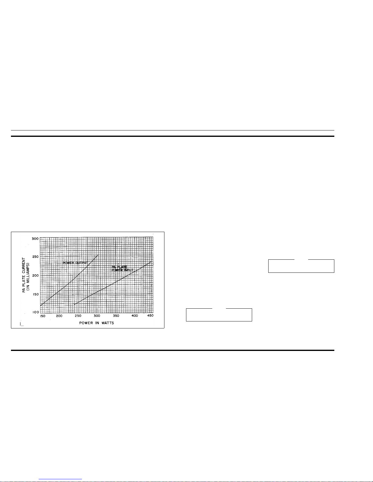
Figure 1 - Power and PA Plate Current Levels
Make sure the PLATE switch on the PA POWER
SUPPLY is in the OFF position.
NOTE
The current readings on the meter includes approximately 25 mA of scree n curren t.
NOTE
ALIGNMENT PROCEDURE
25-50 MHz, 300-WATT
MASTR II POWER AMPLIFIER
MODELS 4EF4A1, 2 & 3
LBI-4938 LBI-4938
2
 Loading...