

Ericsson Marconi OMS 870 Quick Reference Manual

Marconi OMS 870
Quick Reference Guide
R3.0

Copyright
© Ericsson - All rights reserved
Disclaimer
No part of this document may be reproduced in any form without the written
permission of the copyright owner.
The contents of this document is subject to revision without notice due to
continued progress in methodology, design and manuf acturing. Ericsson shall
have no liability for any error or damage of any kind resulting from the use of
this document.

Marconi OMS 870 R3.0 Quick Reference Guide
1/1531-CRA 119 0513/30 Uen A 2007-11-15
Contents
1INSTALLATION
1.1 PRE-INSTALLATION PROCEDURES 1
1.1.1 Shipment verification 1
1.1.2 Preliminary inventory check 1
1.1.3 Reporting damage 2
1.2 SITE PREPARATION 2
1.3 UNPACKING 3
1.3.1 Introduction 3
1.3.2 Unpack the OMS 870 base unit 3
1.3.3 Unpack the OMS 870 service modules 4
1.4 INSTALLATION 5
1.4.1 Installation Overview 5
1.4.2 Installation Planning 6
1.4.3 Installation Guidelines 7
1.4.4 Power Considerations 8
1.5 OMS 870 INSTALLATION 8
1.5.1 Mount in a 19” rack 9
1.5.2 Mount in a 600 mm rack with ETSI brackets 9
1.5.3 Installation in Restricted Access Location (RAL) 10
1.6 INSTALLATION OF POWER MODULES 12
1.6.1 Install the OMS 870 – 48 VDC Power Module 12
1.6.2 External 230VAC - 48VDC Converter 14
1.7 INSTALLATION OF SERVICE MODULES 15
1.7.1 General 15
1.7.2 LEDs 16
1.7.3 Hot insertion and removal 17

Marconi OMS 870 R3.0 Quick Reference Guide
1/1531-CRA 119 0513/30 Uen A 2007-11-15
1.8 INTERCONNECTIONS AND CABLE HANDLING 19
1.8.1 Power cables 19
1.8.2 Alarm cable 19
1.8.3 VT-100 cable 20
1.8.4 LAN cables 20
1.8.5 E1 cables 20
1.8.6 E3/T3 20
1.8.7 Management cable 20
1.8.8 Synchronization cable 20
1.8.9 AUX Port cable 21
1.8.10 Fibre cables 21
1.8.11 Fiber Cleaning 22
1.8.12 Install the OMS 870 Fiber Cable 23
1.8.13 Install the OMS 870 Electrical Cable 24
1.8.14 LFH cables 25
1.9 SFP MODULES 26
1.9.1 Introduction 26
1.9.2 DISCLAIMER 26
1.9.3 Installation of SFP Modules 27
1.9.4 Installing and removing SFP modules 28
1.9.5 Removing SFP modules 30
2 CONFIGURATION OF OMS 870
2.1 INITIAL CONFIGURATION 33
2.1.1 Commissioning of IP address via VT100 Interface 33
2.1.2 Configure User Management (UMA) 36
2.1.3 Assign an IP-address to the OMS 870 38
2.2 FURTHER CONFIGURATION 40
2.2.1 IMPORTANT - System mode from IP to IP un-numbered 40
2.2.2 Further reading 42

1-1
1/1531-CRA 119 0513/30 Uen A 2007-11-15
Marconi OMS 870 R3.0 Quick Reference Guide
1 Installation
1
1.1 Pre-Installation Procedures
This chapter provides pre-installation procedures for the OMS 870.
1.1.1 Shipment verification
When the OMS 870 equipment is received, please verify that the
shipment is according to order.
NOTE! Ship equipment from one site to another in the original
packing including the antistatic bags.
NOTE! Keep the OMS 870 system equipment in the original
shipping containers if storage is required. Storage for more
than 12 months is not recommended. The equipment should
be stored in a ventilated and static-safe location.
1.1.2 Preliminary inventory check
Verify that the packing list information is equal to the information
provided on the shipping labels. Please notify contact resource if
any discrepancies must be reported.

Marconi OMS 870 R3.0 Quick Reference Guide
1/1531-CRA 119 0513/30 Uen A 2007-11-15
1-2
1.1.3 Reporting damage
Damage to shipped articles must be reported to contact resource.
1.2 Site Preparation
Verify that the installation site meets the following criteria:
• The site conforms to all environmental specifications
• The floor or mounting area where you will install the equipment
can support the equipment.
NOTE! The following tables are based on typical OMS 870 system
configurations and may vary in specific customer
configurations.
1. Power supply for the OMS 870 equipment must be available as
described in Table 2
2. Power consumption for the OMS 870 equipment must be
supported as described in Table 2
3. Circuit breakers for the OMS 870 equipment must be according
to Table 2
4. Recommended clearance for accessing the OMS 870 equipment
during and after installation must be as described in Table 1 :
Table 1 Recommended Access Clearance
Table 2 Electrical specifications of DC module
Item Recommended Clearance
Bay access needed for
maintenance
Front access only, 500 mm (19.7 in.)
Back clearance to bays (if
necessary))
500 mm (19.7 in.)
Parameter Limit
Input power dissipation Less than 120W
Fuse 4A
Battery voltage range -40,5 to -72V
Output power 105W

1-3
1/1531-CRA 119 0513/30 Uen A 2007-11-15
Marconi OMS 870 R3.0 Quick Reference Guide
1.3 Unpacking
1.3.1 Introduction
When unpacking and storing OMS 870 equipment:
• Leave equipment packed until it is needed for immediate
installation.
• Store packed equipment in a ventilated and static-safe location
• Store the packaging material in case the equipment must be reshipped.
• If the packaging and/ or equipment is damaged, preserve as
much of the packaging as possible for shipment and damage
analysis.
• Report damage to shipped articles to dedicated contact resource
1.3.2 Unpack the OMS 870 base unit
This section contain specific instructions for unpacking OMS 870
system equipment.
Caution!
When opening a subrack container, use caution to avoid
damaging the contents.
Caution!
Wear a grounding wrist strap while unpacking, handling and
interconnecting the OMS 870 equipment modules, to discharge
any static buildup.
Marconi OMS 870 R3.0 Quick Reference Guide
1/1531-CRA 119 0513/30 Uen A 2007-11-15
1-4
Procedure: Unpack the OMS 870 base unit
1. Open the top of the cardboard shipping container.
2. Take the box containing the OMS 870 accessory kit out of the
shipping container.
3. Lift the OMS 870 out of the packaging box and remove the antistatic bag and foam inserts.
1.3.3 Unpack the OMS 870 service modules
Caution!
When opening a module container, use caution to avoid
damaging the contents.
Caution!
Wear a grounding wrist strap while unpacking,handling and
interconnecting the OMS 870 equipment modules, to discharge
any static buildup.
Procedure: UNPACK THE OMS 870 SERVICE MODULES
1. Open the container and remove the module(s) and packing
material.
2. Carefully remove anti-static bag from the module(s).
3. If any optical adapters are included in the contain er , remove them
and save them for use while installing the module front-panel
optical fiber jumper cables.

1-5
1/1531-CRA 119 0513/30 Uen A 2007-11-15
Marconi OMS 870 R3.0 Quick Reference Guide
1.4 Installation
This section provides instructions before installing OMS 870 unit.
NOTE! The instructions in this section primarily address the
installation of the OMS 870, and modules supplied by
Ericsson . Codes and regulations for installing racks,
electrical wiring, raceways, and other equipment are not
covered in this manual,
Caution!
Wear a grounding wrist strap while unpacking, handling and
interconnecting the OMS 870 equipment modules to discharge
any static buildup.
1.4.1 Installation Overview
You should be thoroughly familiar with the instructions in this
manual before starting any work. Use the following general order of
work when installing a site:
1. Read and observe a ll safet y cautions and warnings in Ch apter 1,
“Safety Summary.”
2. When you arrive at the site, first verify the OMS 870 equipment
according to the procedures in “Pre-Installation Procedures” on
page 1-1. If there is a problem with the equipment, use the
dedicated contact resources for your support
3. If you do not install the equipment when it arrives, store as
specified in “Unpacking” on page 1-3
4. Unpack equipment only after preparing the site as described in
“Site Preparation” on page 1-2
5. When installing equipment at a site, follow the procedures in this
chapter in the order presented.
6. Make connections using the information in “Interconnections and
cable handling” on page 1-19

Marconi OMS 870 R3.0 Quick Reference Guide
1/1531-CRA 119 0513/30 Uen A 2007-11-15
1-6
1.4.2 Installation Planning
Based on the system to be installed, determi ne the size , numbe r
and location of racks, the OMS 870 requires. The OMS 870 will fit in
485 mm (19-in.) equipment racks, and can be adapted for 600 mm
ETSI (23.6-in.) racks. The racks must be accessible from the front
and rear for equipment installation.
NOTE! You need 500 mm (19.6-in.) space of rear access for
installation of the equipment.
NOTE! The interfaces cables (especially E1 interfaces) must not run
in the same pipes as the power cables
Warning!
If mains AC power feeding is employed, the socket outlet shall
have protective earth and be installed near the equipment and
be easily accessible.
Plan rack and unit installation based on the following
considerations:
• Install the lowest unit in a rack first.
• Determine wire size based on cable length and local engineering
standards and practices.
• Plan the power cable from the power distribution panel (PDP) to
units, proceeding down along the right side of the equipment
rack.
• Plan grounding cable runs from the ground window down along
the right side of the rack to the units.
• Plan to route the electrical cables to and from the units along the
right side of the rack to the overhead cable transport tray.
• Plan to route the optical cables to and from the units along the left
side of the rack to the overhead cable transport tray.

1-7
1/1531-CRA 119 0513/30 Uen A 2007-11-15
Marconi OMS 870 R3.0 Quick Reference Guide
Recommended items
To install an OMS 870 system, customary installation and electrical
tools are required. The following items are also recommended:
• Multimeter
• Phillips screwdriver (PH3) to attach the OMS 870 to the rack, and
Phillips screwdriver (PH1) to attach the brackets to the OMS 870,
• Pozidrive (PZ3, PZ1) as an alternative screwdriver
• Allen wrench
• Yellow green flexible ground cable (1.25 - 2.50 sqmm, 16 - 14
AWG)
• Cletop cleaning cassette (type A for SC connectors)
• Video fiber connector inspection instrument
• Caps for optical connectors
• Plugs for optical adapters
•Tie wraps
1.4.3 Installation Guidelines
When installing OMS 870 equipment into racks, follow these
guidelines:
• Consider the effect of additional electronic equipment and its
generated heat on the OMS 870 system equipment.
• Make sure the equipment rack is properly bolted to the ground
and, if required, to the ceiling.
• Ensure that the weight of the equipment does not make the rack
unstable.
• When mounting the equipment between two posts or rails,
ensure that the minimum clearance between the sides is 485 mm
(19 in.).
• Maintain a minimum clearance of 500 mm (19.7 in.) in front of the
equipment and 500mm (19.7 in.) at the back of the equipment.
Grounding Considerations for 48 V
It is vital that the OMS 870 is properly grounded. The OMS 870 can
be connected to ground in the power connector.
Marconi OMS 870 R3.0 Quick Reference Guide
1/1531-CRA 119 0513/30 Uen A 2007-11-15
1-8
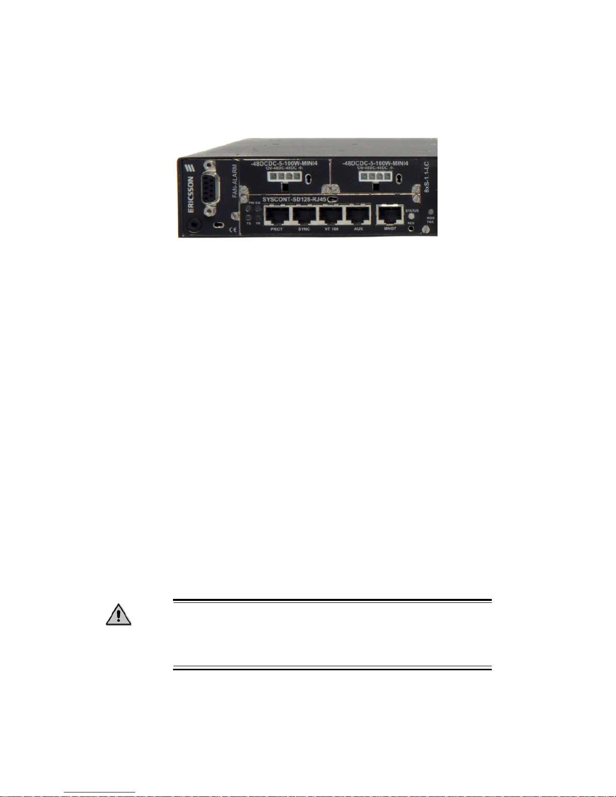
For location of the power connector on the OMS 870, see Figure 1
Figure 1 Location of the power connector on the OMS 870
1.4.4 Power Considerations
The OMS 870 can be powered using a regular telecommunication
power supply of –48 VDC with a VDC return. Two independent
power supplies can be attached to the OMS 870 equ ipm ent. I f two
different supplies are used, they should be independently powered.
1.5 OMS 870 Installation
Use the following procedures to install The OMS 870 in an
equipment rack, verify that at least 3 RU of space is available.
When installing the OMS 870, you can also use the extension
brackets, included in the OMS 870 accessory kit, to convert a 485mm (19-inch) rack to a 600-mm (23.6-inch) rack.
TIP! 1 RU is 44.45 mm.
Caution!
Wear a grounding wrist strap while unpacking,handling and
interconnecting the OMS 870 equipment modules, to discharge
any static buildup.
1-9
1/1531-CRA 119 0513/30 Uen A 2007-11-15
Marconi OMS 870 R3.0 Quick Reference Guide
1.5.1 Mount in a 19” rack
Decide which side do you want to use as the front side. You can use
the side with the connectors or the Ericsson branded side as the
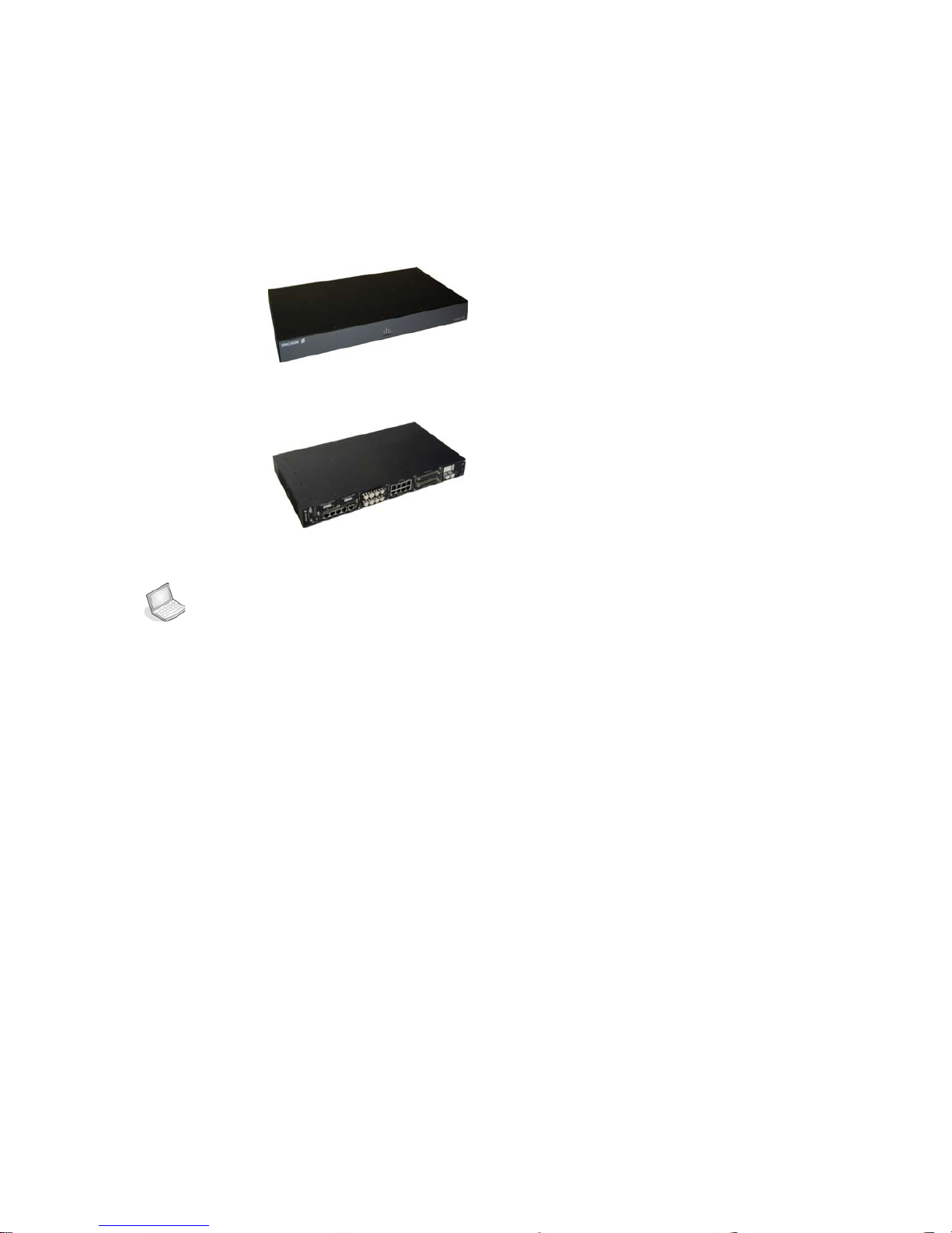
front side if you have rear access.See Figure 2 and Figure 3
Figure 2 Ericsson branded side of the OMS 870
Figure 3 Connector side of OMS 870
PROCEDURE: MOUNT THE OMS 870 IN A 19” RACK
1. Remove the two phillips screws on the left and right and install
the brackets with longer phillips screws that are also in the plastic
bag.
2. Move the OMS 870 to the desired rack position
3. Align four M6 cage nuts in the equipment rack with the mounting
holes on the front of the OMS 870.
4. Align the OMS 870 with the equipment rack and cage nuts.
5. Insert the OMS 870 into the equipment rack.
6. Connect the OMS 870 to the equipment rack with four M6
screws.
1.5.2 Mount in a 600 mm rack with ETSI brackets
The shelf assembly is also possible to install in a 600-mm (23.6-in.)
rack, for this installation you can use extension brackets. You will
need two 1 RU extension brackets for this procedure.

Marconi OMS 870 R3.0 Quick Reference Guide
1/1531-CRA 119 0513/30 Uen A 2007-11-15
1-10
Decide which side do you want to use as the front side (you can use
the side with the connectors or the Ericsson branded side as the
front side) depends on if you have back access
1. Remove the two phillips screws on the left and right and install
the extension brackets with longer phillips screws that are also in
the plastic bag.
2. Follow step 2-6 in “Mount in a 19” rack” on page 1-9.
1.5.3 Installation in Restricted Access Location (RAL)
The OMS 870 can be installed in a restricted access location (RAL)
or outside of an RAL.
After installation in a RAL, such as in a telecommunication centre,
the OMS 870 must be properly installed in a rack with b racket s or in
other ways properly connected to a safety ground.
The OMS 870 48V DC must not be powered from a source external
to the RAL. All communication interfaces used must be limited to
SELV. E1 interface used should be limited to SELV.
1.5.3.1 Installation outside a Restricted Access Location
After installation, the OMS 870 48V power and all communication
ports used must be connected to SELV circuits, for example a port
on a personal computer or 10/100 Mbit Ethernet hub/router or other
Information Technology (IT) equipment.
The 48V DC power must not exceed 60 VDC and must be powered
from an certified external power supply unit (PSU) or a battery unit
(no connection to -48 V telecom voltage).
The optical ports (if present) have no limitations regarding safety
recommendations.
1.5.3.2 Definitions
Restricted Access Location (RAL)
A location for equipment where both of the following paragraphs
apply:
• Access can only be gained by service persons or by users who
have been instructed about the reasons for the restrictions
 Loading...